We specially want to thank all our partners involved in the CAPTHOM project. This work was realized with the financial help of the French Industry Min- istry and ...
Reliability, Risk and Safety: Theory and Applications – Briš, Guedes Soares & Martorell (eds) © 2010 Taylor & Francis Group, London, ISBN 978-0-415-55509-8
Automating the synthesis of AltaRica Data-Flow models from SysML P. David, V. Idasiak & F. Kratz Institut PRISME, ENSI de Bourges, Bourges, France
ABSTRACT: The work presented in this article, completes the description of an engineering framework aiming at integrating the reliability analysis practices within the functional design process. The described method is structured into a SysML context and proposes the execution of varied safety and reliability analyses as FMEA. The first steps were presented in our previous papers and namely in (David et al. 2008, 2009). This paper is centred on connecting this method to current efficient techniques to obtain and quantify failure scenarios. It focuses on how to exploit SysML models to construct semi-automatically models in AltaRica Data Flow (Rauzy 2002). The method, presented, proposes to construct the AltaRica Data Flow model from the results of the functional analysis and from those obtained during a risk analysis. In order to realize this step, the semantics of both languages are studied and compared. Namely, we focus on finding models the expected elements to construct the AltaRica Data Flow model, in the SysML. 1
INTRODUCTION
Over the past decade, the complexity of safety critical systems has considerably grown. Systems have become larger and now involve a huge diversity of technologies. For instance, software components are widely embedded in systems regrouping electronic devices, sensors, actuators and mechanical structures. Developers impose precise requirements on these new systems concerning dependability, performance, correctness and safety. Well-specified modelling methods and languages are needed to manage their development, but also for the validation of their design. The study of these new systems brings up the issue of performing reliability studies during the conception phase. Standards like the IEC 61508 (1998–2005) propose a succession of tasks to develop safety critical systems. Nevertheless, these standards precisely define the analysis to produce but do not provide methods to efficiently conduct them. Therefore, there is a real need in today’s industry to obtain tools and methods to support the design of safety critical systems, by linking classical methods of each specialist working on those projects. The purpose of System Engineering (SE) is to schedule techniques to develop solutions in response to diverse stakeholders needs (Friedenthal et al. 2008). Those needs include reliability and safety aspects. Model-Based System Engineering (MBSE) (Estefan 2008) is nowadays considered as the best approach for the design of complex systems. It is supported by methods like the Object-Oriented System Engineering Method (OOSEM) (Lykins et al. 2000) for which SysML is well-adapted. In order to fulfil the SE goals until the validation of the designed systems, reliability analysis must
be conducted. Therefore, we focused on integrating classical dependability study techniques in SE frameworks. Namely, in this article we analyse how to use languages like AltaRica Data Flow (DF) (Rauzy 2002) in those frameworks. This task is mainly performed by translating models. The remaining of this paper is organized as follows. In the second section, we will discuss the integration of reliability analysis in SE frameworks. In section 3, we will present the method we developed to integrate reliability studies in a SE development process. Sections 4 and 5 will introduce the AltaRica DF language and expose the translation created with SysML. In section 6, we will exemplify the approach by continuing a study presented in (David et al. 2009). 2
MODEL-BASED SYSTEM ENGINEERING AND RELIABILITY STUDIES
2.1
Developing complex systems with System Engineering
The global issue tackled by our research is to organize the development of complex systems satisfying strong reliability constraints. The complexity of such systems comes from various required features: • • • • • •
Large-scale system Multiple technologies employed Complexity of functionalities Huge interoperability High performances High reliability and safety
In order to manage those aspects, the designers’ community set up standardized techniques to institutionalise the practices of SE throughout the products
105
lifecycle. The standards deal with the SE processes that define the set of tasks to perform, the modelling methods that emphasize on how to perform the tasks, and the modelling languages that furnish a consistent set of artefacts to represent systems. The standards on development processes give the fundamental tenets of SE to manage the system development project. The IEC 61508 is the most used for the design of safety critical systems. This standard for the functional safety of electrical/electronic/ programmable electronic safety related systems can also be applied to other application fields. It provides a description of the “safety lifecycle” that describes the tasks to be performed throughout the life of the product to reach and insure a given “safety integrity level”. A short description of the standard and its vocabulary is given in (Larish et al. 2008). The SE methods give instructions to apply the SE processes, as they define the kind of artefacts needed during each phase and how to relate them. Most of these methods now are MBSE methods (Estefan 2008) in contrast with Document-Based approach. These methods support the analysis, specification, design and verification of systems with the exploitation of a centralized model. Using an MBSE method offers important benefits summarized in (Friedenthal et al. 2008): • • • • •
Enhanced communications between development teams Reduced development risk Improved quality Increased productivity Enhanced knowledge transfer
One of the most popular methods is the OOSEM, using SysML as a supporting language and mainly developed by the International Council on Systems Engineering. It is an iterative approach covering the following set of activities: • • • • • •
Analyse stakeholder needs Define system requirements Define logical architecture Synthesize candidate allocated architecture Optimise and evaluate alternatives Validate and verify system (or sub-system)
The last components introduced for SE are the tools utilised to support the activities suggested in the SE method. For the OOSEM approach, the tools are the SysML modelling tools created to support the drawing and organization of models. Tools are also needed to manage the whole project and particularly for the realization of the chosen SE process. The nesting of the diverse tools (e.g. for requirements management, project management or model analysis) is designated as a System Development Environment (SDE). 2.2
Integrating reliability studies in SE processes
If we refer to the class of systems for which reliability studies are necessary, it is natural to choose the IEC
61508 as a standardized SE process. This choice is also justified in (Signoret et al. 2007) and (Larish et al. 2008). In our previous works (David et al. 2008, 2009), we justified that SysML was well-suited to support reliability studies, like FMEA process and to design complex systems integrating multi-technological parts. (Larish et al. 2008) presented how the application of IEC 61508 can be assisted by the use of SysML models. Namely, they presented the kind of diagrams that could be used in the different phases of the “safety lifecycle” of the IEC 61508. Our previous works (David et al. 2008, 2009) proved that parts of this cycle could be automated. Those elements let us assume that SysML is the right modelling language to use for the development of complex systems satisfying strong reliability constraints. Therefore, OOSEM seems to be the right SE method to use to cover the IEC 61508 process with SysML. It is thus important to define how the reliability analysis can be integrated in such a method. This integration is performed along two axes. On the one hand, activities are defined in the method deployment, on the other hand the connection of tools for the supporting SDE are set up. In fact, the added activities reuse the already well-known reliability analysis like FMEA, dysfunctional models with Generalized Stochastic Petri Nets (GSPN), Markov Processes (MP) or AltaRica DF simulation and analysis. These activities permit to obtain failure scenarios, reliability indicators and to assess the performances of the system. The tools used to conduct these studies have to be connected in the SDE and namely to the SysML modelling tool. Figure 1 exposes the model centred framework induced by the use of the OOSEM. The diverse activities, symbolized by the arrows, are organized in time with the SE process and method. Each activity involves the use of a tool as well as the creation of the system model in SysML. The reliability and risks analyses take place in several activities. The project management that executes the traceability rationale will have to manage requirements on safety and reliability. The system documentation will be augmented with normative documents assessing the execution of risks study as FMEA. Moreover, those documents are created by the realisation of dedicated reliability and safety analyses that join the analysis needs and performances estimates activities. The reliability and safety analysis needs for complex safety critical systems development are not in contradiction with the current techniques used in SE. The effort consists in detailing new kinds of requirements and integrating the new type of analysis techniques and tools to the common SDE. Nevertheless, it imposes on the project management to define when the diverse phases of reliability and safety studies must be conducted. Indeed, it is impossible to quantify and to assess the dysfunctional behaviour of a system, only with a traditional functional model employed in classic SE. The study of the system must go through multiple phases, from the risks and failure mode identification
106
Figure 1. Model centred framework in OOSEM – inspired by (Friedenthal et al. 2008).
to the global reliability assessment. Moreover, those tasks have to be performed iteratively at several abstraction levels. In section 3 we propose a method to schedule those reliability and safety analysis tasks. Finally, to obtain an efficient integration of reliability and safety analysis in the SDE, it is important to create connections between various employed tools. The connections can be done by exploiting the same modelling language and by integrating various analyses of the model in a unique tool, similarly to the documents generation proposed by the majority of SysML modelling tools. It may also be interesting to create interfaces between existing tools, by exchanging files created with translation algorithms. These two approaches can also cohabit. This is the solution we proposed, with our method aiming at integrating reliability studies in MBSE for the development of safety critical complex systems.
3
ORGANIZING AND SUPPORTING RELIABILITY ANALYSIS IN MBSE
The aim of our work is to be able to analyse real conception models expressed in SysML and to perform the validation of safety and reliability requirements. Consequently, we are developing a method using techniques that can be mainly realized automatically by software tools. We propose a deductive and iterative method in three steps described in Fig. 2: •
Deduction of the dysfunctional behaviour with an FMEA, identification of the impacted requirements. • Construction of a model integrating functional and dysfunctional behaviours with a formal language. • Analysis and quantification of dysfunctional behaviour. These steps are realized for each system or subsystem analysed during the SE process. Therefore, they are preceded by a system boundaries definition
Figure 2. Reliability analysis method.
phase and a safety and reliability requirements allocation. The steps are iteratively conducted throughout the breadth and depth of the designed system. Each type of analysis requires dissimilar models and methods. Our role is to enhance the link between each activity and its integration in a SDE. The goal of each step is to generate new knowledge or to automatically create new models for various analyses. This knowledge is joined to the model repository realising the centralisation of information in an MBSE method. The aim of the whole process is to trace the impacts of failures on the system performances and reliability requirements. At the beginning of our approach, we assumed that a model expressing the architecture and the functional behaviour of the system had been set up by designers during the first phases of the SE process. Additionally, as SysML offers great facilities to manage requirements, we expected performance and reliability requirements to be declared and allocated. The search for the initial dependability and reliability requirements can be done with the help of classical practices like Preliminary Hazard Identification or Functional
107
Hazard Analysis. The second assumption is that developers have access to information on the dysfunctional behaviour of the components usually utilized in design. This base of information can be the result of studies on previous exploitations of similar components in systems already in use. In (David et al. 2009), we proposed a way to formalize this database using SysML. If such a database is unavailable, the process will contribute to building one, but the automatic phases will be less efficient. The first operation is to find what may cause failures in the functioning of the system. Therefore, an FMEA of the system is established. This FMEA is generated from the study of SysML models. FMEA provides a systematic detection of risks and failures at an early stage of the design process. It guarantees the exhaustive identification and the classification of failures. This step is very critical because it has to highlight the Failure Modes (FM) that will be qualified and quantified in the remaining of the study. In order to generate the FMEA from SysML models, we apply techniques of data translation using files exploiting XML (eXtensible Markup Language). This phase and its benefits have been presented and discussed in (David et al. 2008, 2009). The results of the FMEA are used to enhance the model repositories with the knowledge of the dysfunctional behaviour of the system. Then, it is necessary to compute the impacts of the identified FM at the system scale in order to verify the requirements. This step uses formal languages and formalisms that reliability engineers developed. These languages are mandatory in order to accurately compute the performance and reliability indicators, as well as for proving the system behaviour. The operation that must be executed is the computation of models for reliability evaluation, thanks to the identification of the dysfunctional behaviour performed by the FMEA. It exists numerous formalisms to perform this task: we can propose the AltaRica DF or Figaro (Bouissou & Bon 2003) languages, or widely used concepts like GSPN or MP. We focus on using languages exploiting semantics similar to the Object-Oriented definition of SysML. AltaRica and Figaro use very close syntaxes, as the models are constructed as lists of nodes representing components or subsystems. The construction of the model is done component by component, so that the decomposition established in the FMEA can be naturally reused. Moreover, these models highlight the error propagation between components by describing the flow ports and the state of the flows passing through them. Experts in reliability studies generally build these models manually. The main interest is not to change their methods, but to help them build the models by enhancing the reuse of knowledge raised in the previous steps of the process. We focused on using the AltaRica DF language that benefits from a huge implantation in software tools (BPA DAS by Dassault Systems, Aralia workshop by Arboost Technologies) largely used by reliability experts. These software tools enable to quantify reliability indicators, such as global failure rates, mean
times to failure or probabilities of failure on demand, as well as the computation of FaultTrees (Rauzy 2002), (Boiteau et al. 2006), (Signoret et al. 2007). The last step of our approach is to use these kinds of tools on the previously obtained models in order to compute the necessary results for design evaluation and orientation. These results can also be used to update the information registered in the dysfunctional model repository. In order to integrate these practices in the global SDE and to make it applicable during the SE process, it is highly recommended to assist as much as possible the AltaRica DF model creation. The fusion of tools is impossible as they exploit dissimilar models. Therefore, to perform this task, we have to analyse and translate the SysML model in AltaRica DF and to reemploy the results of the FMEA for its creation. In the two following sections, we will introduce the AltaRica DF and propose a support for the models creation from analyses and translations of SysML ones. 4 ALTARICA DATA FLOW AltaRica DF is an adaptation of the AltaRica language described in (Arnold et al. 2000). It simplifies the preceding specification, and has been specially designed to support reliability analysis. The language relies on the mode automaton formalism described in (Rauzy 2002). The description is very close to statecharts and can be seen as a generalisation of GSPN and block diagrams. The introduced modifications allow the computation of Boolean formulae leading to the creation of fault trees or detection of failure scenarios. Systems are modelled via the description of their component and with an Object-Oriented approach. Components are declared in a hierarchical way, they communicate by flow exchanges and action synchronisations with events. An AltaRica model is a tree-based structure whose root node is the complete system and whose leaves are the unitary components. Evolutions of the system are assumed to be asynchronous (changes of state imply an instantaneous change of flow treatment). Nodes representing type of components are the basic elements of AltaRica DF models. A Node is characterized by its reachable states, treated flows and the receivable events. The state variables (key word: state) denote the system states, the flow variables (key word in AltaRica DF: flow) are used for the communication between components and to reflect the component processing. The component processing is defined as a relation between the inputs, the current state and the outputs transmitted to the environment (key word: assert). In AltaRica DF the relations can be either logical or algebraic. The component reacts to events that model the evolution possibilities as well as the interaction with environment. Namely, operators’decisions or environmental hazards are expressed by events, the failures are therefore modelled by events. Transitions (key word: trans) describe the next values of state variables computed after the reception of events. The
108
composition relationship between nodes is also modelled by defining sub nodes constituting the described node (key word: sub). Nodes are synchronized by the flow exchanges and by the events propagation throughout the structure. These mechanisms allow to model failure propagation and simultaneous faults. The occurrence rate of events can be quantified and precised with classical probability laws (key word: extern law). This last feature of AltaRica DF allows to perform quantified performance and reliability studies, for instance using Monte Carlo simulation. 5
SUPPORTING ALTARICA DF MODELS CREATION WITH SYSML ANALYSIS
In this section we study the model translation between SysML and AltaRica DF. The objective is to integrate the study of reliability aspects with AltaRica DF models in the OOSEM relying on SysML models. The translation will permit to add tools like BPA DAS in the SDE. The creation of the reliability analysis cannot be fully automated, the experts validation is mandatory to conduct consistent and expressive studies. The reflections that we present here, are formulated to support as much as possible the highlighting of the dysfunctional behaviour in AltaRica DF. As we will see, parts of the techniques exposed can be automatically performed while others are guidelines and methodologies for reliability studies experts. We will expose how the AltaRica DF model can be set up by analysing architecture, behaviour and the dysfunctional aspects of the system. For different studies, the SysML model may be constituted of various kinds of diagrams depending on the modeller’s needs. Therefore, the translation must take into account the fact that information search must exploit various kinds of views. For instance, statecharts may or may not be drawn in the model. As this formalism is very close to mode automata, we assume that their exploitation to create AltaRica DF models does not represent significant development efforts. Therefore, we focus in this paper on translating SysML models that do not embed statecharts. 5.1 Architecture translation Up to this point, SysML notations are in italics and AltaRica DF ones are in bold. The dysfunctional behaviour modelling begins by representing the structure of the system to analyse. This step needs to be consistent with the architecture defined in the first phases of the SE process. Therefore the first analysis is to exploit the architectural view of the SysML model. This axis is represented in Block Definition Diagrams (BDD) and Internal Block Diagram (IBD), which respectively model the concepts utilized within the model and the instantiation of those concepts in the context of the studied problem. An automatic AltaRica DF code is defined transforming the structures of SysML in AltaRica DF nodes. First, all the AltaRica DF nodes declarations and compositions are declared
by the BDDs study. Then the synchronisation of flow exchange is performed by the analysis of IBDs. The SysML blocks possess several properties allowing the creation of AltaRica DF nodes. The exploited block features are the followings: name, value properties, port properties, part properties. Each identified block leads to the creation of a node, the name is used to insure the traceability across models. Each part property is translated as a sub node of the designed one. The name and type of this sub node are the same as those used by the part. The consistency is guaranteed, as each block type used to type parts will also be translated by nodes in the AltaRica DF model. The port properties define the exchange gate of components. Their SysML definition is consistent with the declaration of AltaRica DF flow variables, because they are both characterised by a name, a type (declaring the passing flow) and a direction imposing the way the port is used. Therefore a flow variable taking the same name, type and direction is created for each port property owned by the traduced block. The value properties define the variables describing the component state, they correspond to the state variables of AltaRica DF that inherit their name and type. These translations permit to obtain the structural part of the final AltaRica DF model. The declaration of several nodes and their utilization to type sub nodes modelling the component of the global system reuse the same description found in the SysML model. Nevertheless, the AltaRica DF presents several restrictions that complicate the direct translation. Adaptations have to be proposed to perform an automatic translation. First, the AltaRica DF restricts the usable types for the variables to boolean, float and enumeration. Moreover, flow directions are unidirectional (in or out). The liberty offered by SysML to the modeller makes this language very expressive but complicates its translation in AltaRica DF, even if the modelling approaches are similar. With SysML, the typing elements can be a block, a value type or a data type. Therefore, to automate the translation of flow and state variables, the SE method must impose variables typing restriction or propose type equivalences for the reliability study step. The second solution offers a more expressive model for central point of the SE process, which is then degraded according to the needs of the specific surrounding studies. The second point is the declaration of the flow variables. In AltaRica DF, the flow variables and the port are considered as one modelling element whereas in SysML, ports are declared but the modified variables representing the flows received or sent must be independently declared. Nevertheless, allocation relationships provide a manner to explicitly link a port and a variable. Therefore, we can enunciate a new modelling rule for the SE method, which is that each flow variable must be allocated to a port at the allocated from end of the allocation relation. We can notice that this rule is totally consistent with relevant functional modelling methods relying on functional analysis. In order to treat bi-directional flow ports, we propose to duplicate the
109
flow variables used in the AltRica DF model. This translation must be completed by an equality assertion between the two created variables. Considering that the model has been constructed with the two stated modelling rules, an automatic synthesis of the structural part of the AltaRica DF file could be performed. This step relies on simple file analysis and translation rules. The analysis can be performed thanks to the exportation files furnished by the SysML tools. Those files exploiting the formalized XMI format provide the lists of model elements. The exploitation techniques of these files have been given in (David et al. 2008, 2009). 5.2
Behaviour definition
Table 1.
SysML and AltaRica DF Behaviour part.
SysML element, diagram type and element properties.
Usage in AltaRica DF node behaviour description
Operation Operation body
Event Affectation (transition), assertion Affectation (trans.), assertion, guards (trans.). Guard (trans.), events synchronisation Event Event Affectation (trans.) Affectation (trans.), Assertion. Guard (trans.), event synchronisation. Guard (trans.), event synchronisation.
Constraint allocated to operation Message timing Activity allocated to block Action allocated to block Constraint allocated to Action Constraint property of block Activity Diagram
The structural view of the system must then be completed by the expression of the system behaviour. During the previous phases of the SE method, the functional behaviour has been described. The first task to perform is to translate this behaviour in the AltaRica DF model. For this phase, we assume that the behaviour has been allocated to the architecture. We can thus add a rule to depict a functional modelling approach well-suited to prepare risk and reliability analysis, which is the allocation of the behaviour to precise architectural elements. We can notice that those allocation steps are clearly parts of the OOSEM, where “logical nodes” are allocated to “physical nodes”. The behaviour of AltaRica DF nodes is written in assertions and transitions as presented in section 4. The task of behaviour modelling consists in identifying the SysML elements that reflect the events, affectations and guards that constitute the assertions and transitions. The SysML elements that depict the behaviour and linked to blocks are the followings: operations, allocated statemachines (which are not part of this study), allocated activity and actions, sent andreceived messages and constraint properties. The operations’ executions are called by an action or a message. Activities are composed of actions that are synchronized and organized. The actions are not necessarily linked to operations but can also provoke signal sending. The constraint properties express relationships satisfied by the value properties and other values of the system. We observe that very heterogeneous modelling constructs have to be treated to reflect components behaviour. Moreover, the semantics of these elements is larger than the duality assertion/transition of AltaRica DF. For example, execution of operation can model output changes as well as state variables modifications. These two aspects are respectively modelled by both assertion and transition. Therefore an automatic translation of the behavioural view in the AltaRica DF model is not possible. Nevertheless, an aided analysis of the SysML model provides a great support for this step of the AltaRica DF model creation. Namely, we can provide a service that proposes lists of possible events, transitions and assertions found in the SysML model, for each node.
Sequence Diagram
Table 1 sums up the utilisation of SysML elements to guide the creation of the behavioural part of the AltaRica DF model. Events model a state change or the beginning of a punctual treatment realised by the component. Therefore, in SysML they can be seen as operation starting (caused by messages or actions) and as activity or action starting. Guards restrict the treatment of these events, these restrictions are expressed when the dynamic of operations and actions chaining is modelled. Consequently, guards can be found in interpreting Activity and Sequence diagram, where the conditions of starting an action or sending a message are expressed in logical or timing manner. The affectation part of transitions models the impact of the treatment triggered by events. The affectations consist in constraining the values of outputs and state variables. Only two SysML modelling constructs are capable of representing this kind of behaviour: operation body and constraint property modelled in Parametric Diagram (PD). To understand that these constraints must be used for AltaRica model creation, allocations must have been defined between operations, actions, activities and constraints properties. Identically, the constraint properties of the translated SysML blocks that model the relations verified by block value properties are proposed for assertion writing. The consistency with the structural part is insured as the constraint properties are linked in PD to the value properties of blocks owning the names defined in the phase depicted in 5.1. The events synchronisation throughout system architecture is presented in Sequence Diagrams and Activity Diagrams where the sequences of messages and actions are exposed. We observe that it is possible to underline all the relevant parts of the SysML model to analyse for the users. Nevertheless, it is only possible to guide the expert exploitation of a huge model and to furnish propositions of translation. For example, by analysing the variables natures to consider if the constraints
110
binding them is an affectation or an assertion. However, some simple modelling rules added to the SE method could allow the full automation of this step (e.g. allocating constraint to each block expressing the relationship between inflows, states and outflows; using only “CallOperationAction” in the Activity Diagrams refining the block behaviour). At this step of our study it would be interesting to consider how much statemachines reduce the modelling effort with SysML. 5.3 Adding dysfunctional aspects In order to finalise the model for reliability analysis using tools like BPA DAS, the last phase consists in adding the dysfunctional behaviour on the AltaRica DF model of the system. This step is devoted to the experts, but is also supported as a part of the SE process. The necessary information has been identified thanks to the preceding tasks of risk analysis. Namely, the results of the FMEA are injected in the model. The structure of the FMEA relies on the SysML model architecture as well as on the AltaRica DF model structure. Thus the FM obtained for the system blocks are directly affected to the nodes. The study can be performed from the textual form of the FMEA or by using its results that have been passed to the SDE repositories. The management of the dysfunctional behaviour repository can dramatically support the creation of the dysfunctional view for AltaRica DF model. The creation of this repository has been discussed in (David et al. 2009), where the opportunity to associate a PD to each registered failure modes has been underlined. SysML specification offers the opportunity to embed AltaRica DF code within these diagrams, making them directly reusable for our purpose. An alternative solution is to associate a statemachine to the FM, making the automatic translation available. 6
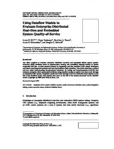
CASE STUDY: THE LEVEL CONTROL SYSTEM
We will illustrate the automatic part of the AltaRica DF model construction by a case study on a Level Control System (LCS) mounted on a tank that contains an unspecified fluid. The LCS is detailed in (David et al. 2009), the system is summarized in the IBD of Fig. 3. From the analysis of the information presented in this diagram, we can obtain a crucial part of the AltaRica model: the structural view. This structure is coherent with the one detailed during the design process and presents a traceability in the naming policy. This fraction of the model is the frame on which the behavioural descriptors are attached, its quality facilitates the realisation of relevant reliability studies. Figure 4 shows an excerpt from the AltaRica DF file created for the architecture of the LCS. This fragment concerns the node of the LCS seen as a whole. We can note that the sub-components have been identified, as
Figure 3. IBD of the LCS.
Figure 4. Excerpt of AltaRica DF file describing the LCS.
well as the flow and state variables. The division of bi directional flow ports mentioned in 5.1 is performed for In1LCS and In2LCS, creating 4 flow variables prefixed by “in_” or “out_” and introducing 2 equality assertions. Finally, the connections of the LCS components are written in the assertion clause. The type of the flow variables has been adapted from the specially defined one “Fluid”, to the AltaRica compatible one “float”. The translation created the whole structural view for each node referring to each kind of component like: Sensor, PowerSupply or ElectroValve.
7
CONCLUSION
In this article we presented techniques to support the reliability studies of system using AltaRica DF and its supporting tools in an OOSEM context. The creation of AltaRica DF models is aided by SysML models exploitation in order to integrate these tenets in an SDE. This step is part of a method permitting the integration of risks and reliability studies in the SE processes using OOSEM. We have shown the possibility to share knowledge between functional modelling in SysML and the dysfunctional behaviour analysis. The reliability analyses can be realized more efficiently and rapidly. Nevertheless, this work is just a first example of what the collaboration of SysML and the
111
well-known reliability studies can offer. For instance, the use of SysML views can support the definition of the needed analysis framework for relevant reliability studies. Namely, it could provide ways to adapt the level of description and to select the relevant system parts and behaviour descriptions that have to be considered. Indeed, the ability of SysML to model large systems with multiple interfaces, multiple abstraction layers, multiple views corresponding to diverse stakeholders needs, can be exploited to enhance the use of the very specialised techniques utilized for reliability and risks analysis, in a coherent SDE supporting well-mastered SE processes and methods. ACKNOWLEDGEMENTS We specially want to thank all our partners involved in the CAPTHOM project. This work was realized with the financial help of the French Industry Ministry and local collectivities, within the framework of the CAPTHOM project of the Competitiveness Pole S2 E2 , www.s2e2.fr.
REFERENCES Arnold, A. Griffault, A. Point, G. & Rauzy, A. 2000. The AltaRica language and its semantics. Fundamenta Informaticae 34:109–124. Boiteau, M. Dutuit, Y. Rauzy, A. & Signoret, J-P. 2006. The AltaRica data-flow language in use: modeling of production availability of a multi-state system. Reliability Engineering & System Safety 91:747–755. Bouissou, M. & Bon, J-L. A new formalism that combines advantages of fault-trees and Markov models: Boolean
logic driven Markov processes. Reliability engineering and system safety 82:149–163. David, P. Idasiak, V. & Kratz, F. 2008. Towards a better interaction between design and dependability analysis: FMEA derived from UML/SysML models. Proceedings of ESREL 2008 and 17th SRA-Europe Annual Conference, Valencia, Spain, Sept 2008. David, P. Idasiak, V. & Kratz, F. 2009. Improving Reliability Studies with SysML. Proceedings of the 55th Annual Reliability and Maintainability Symposium, RAMS 2009, Fort Worth, Texas, USA, Jan. 2009. Estefan, J. 2008. Survey of Model-Based Systems Engineering (MBSE) Methodologies, Rev. B. INCOSE MBSE Initiative, 23 Mai 2008. Friedenthal, S. Moore, A. & Steiner, R. 2008. A Practical Guide to SysML : The Systems Modeling Language. The MK/OMG press, Elsevier. IEC 61508. 1998-2005. International Electrotechnical Commission. Functional Safety of Electrical /Electronic /Programmable Electronic Safety-Related Systems. Parts 1 to 7. Larish, M. Hänle, A. Siebold, U. & Häring, I. 2008. SysML aided functional safety assessment. Proceedings of ESREL 2008 and 17th SRA-Europe Annual Conference, Valencia, Spain, Sept 2008. Lykins, H. Friedenthal, S. Meilich, A. 2000. Adapting UML for an Object-Oriented systems engineering method (OOSEM). Proceedings of the 10th annual INCOSE symposium, July 2000. OMG 2008. OMG Systems Modeling Language (OMG SysML) V1.1. 1st November 2008. Rauzy, A. 2002. Mode Automata and their compilation into Fault tree. Reliability Engineering and System Safety 78: 1–12. Signoret, J-P. Dutuit,Y. & Rauzy, A. 2007. High Integrity Protection Systems (HIPS) : Methods and tools for efficient Safety Integrity Levels (SIL) analysis and calculations. Proceedings of ESREL 2007 Stavenger, Norway, June, 2007.
112