10,000 AutoBrakits designed and documented for traceability and repeatability
on a global basis. Aut. Flowserve Corporation's. Automax Valve Automation.
(AUTO-95) PneAct & Access #18 9/24/04 10:04 AM Page 3
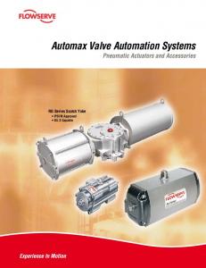
Automax Valve Automation Systems P N E U M A T I C A N D
A C T U A T O R S
A C C E S S O R I E S
NEW
Quality System Certificate
Quality, Dependability and Productivity
© TriCom, Inc., 2004, All Rights Reserved.
FCD AXABR0005-02 (Bulletin AUTO-95)
(AUTO-95) PneAct & Access #18 9/24/04 10:04 AM Page 4
Flow Control Division Automax Valve Automation Systems
F
lowserve Corporation’s
Automax Valve Automation Systems provides complete valve and damper automation to the worldwide processing industries. We provide maximum value to the end user through a broad offering of products, services, application
Quality, Dependability and Productivity Recognized as the leader in valve automation systems, Automax pneumatic actuators can automate valves with torque values from 25 to 500,000 in-lbs. Actuators are available in a wide range of materials suitable for use in the most demanding applications. Flowserve also offers a comprehensive range of NAMUR Controls and accessories such as lockout modules and gear overrides. To complete the package Flowserve can provide engineering design services for AutoBrakit Mounting hardware. We currently have more than 10,000 AutoBrakits designed and documented for traceability and repeatability on a global basis.
engineering and our systematic approach to automation.
2
© TriCom, Inc., 2004, All Rights Reserved.
Aut ©
(AUTO-95) PneAct & Access #18 9/24/04 10:04 AM Page 5
S
SuperNova SuperNova B Series Rack and Pinion actuators are designed for butterfly, plug or ball valves, and offer one compact design for double acting and spring return. Precision die-cast pistons with large cylinder bearings increase efficiency and cycle life. Available in torque ranges from 25 to 58,000 in-lbs, for optimum actuator sizing.
ales and service facilities
are strategically located in industrial centers throughout Page 8
the world.
Controls & Accessories The actuator is the heart of an automation system, but control accessories are important in creating a complete system to meet increasingly sophisticated customer requirements. Solenoid valves and related accessories with NAMUR interfaces provide direct, modular mounting on actuator. Switches, Positioners, Gear Overrides and Lockout Modules can also be integrated into the assembly. AutoBrakits are engineered to assure consistency and proper alignment.
Page 9
Stainless Steel The SXL® Series utilizes a 316 Series stainless steel housing and is ideal for use in corrosive environments. It is available in both double acting and spring return and can be supplied with internal components identical to the SNA Series or with optional stainless steel internals. For sanitary applications the housing can be polished. Available in torque ranges from 78 to 7279 in-lbs.
Page 10-11
tomax Heavy-Duty R2, R3, R4 and R5
A complete line of Scotch Yoke heavyduty actuators provides torques from 3,000 to 500,000 in-lbs. The combination of Scotch Yoke actuators plus Rack and Pinion actuators offers the opportunity to standardize on one source for your complete quarter-turn automation needs. Scotch Yoke actuators can also be configured with high pressure hydraulic cylinders.
Page 12-17
3
© TriCom, Inc., 2004, All Rights Reserved.
(AUTO-95) PneAct & Access #18 9/24/04 10:04 AM Page 6
SuperNova B Series Double Acting
R
ack & Pinion Actuators
are designed for automating butterfly, plug or ball valves Broad size range offers optimum actuator sizing for each valve requirement.
and dampers. The actuators incorporate a precisionextruded hard anodized aluminum body and a one-piece nitride-coated
Flats on Pinion Drive Shaft accommodates wrench overrides and accessories.
pinion gear, factory lubricated for a long
NAMUR Mounting Dimensions on actuator accessory holes and drive shaft.
NAMUR Mounting Dimensions on actuator pneumatic port connections.
Upper and Lower Pinion Bearings extend life.
trouble-free life. Actuators are designed for 100-degree travel with clockwise and counterclockwise travel adjustment for open and closed positions.
* Outward piston adjustment only on models SNA250 & SNA300
Integral Travel Stops in both directions with 10 degrees of overtravel to assure precise adjustment of both the open and closed positions.*
Dual ISO Mounting Pad provides ease and flexibility in direct valve installation.
Full Length Gear Engagement between piston rack & nitride-coated pinion.
Precision Die Cast Pistons with large cylinder bearings increase efficiency and cycle life.
4
© TriCom, Inc., 2004, All Rights Reserved.
©
(AUTO-95) PneAct & Access #18 9/24/04 10:05 AM Page 7
SuperNova B Series Spring Return The most useful properties of the oxide coating are: • The oxide coating is integral with the base substrate and will not spall off by impacting thermal shock nor to temperatures to aluminum’s melting point. The oxide has negligible effect on the other properties of aluminum. • Aluminum oxide is one of the hardest materials known with a hardness of corundum (45 to 65 Rockwell C). Further, abrasion tests show only half as much wear as hardened steel. • Aluminum oxide is relatively stable and chemically inert. The oxide is usually stable over a pH range of 4.5 to 8.5, but can be dissolved by strong acids and alkalis, where as it normally resists concentrated nitric acid at pH 1 and ammonium hydroxide at pH 13.
A
utomax Aluminum Alloy
Hard anodic oxidation is an electrolytic conversion process which results in the formation of an oxide film. Continuation of the process produces the “hard”
One Compact Design for double acting and spring return is easily field convertible by installing or removing springs.
Field Reversible action simply by rotating pistons 180°.
anodic coating to two mils. The chemical composition provides the optimum alloy for strength, abrasion resistance, cold working and chemical resistance.
Corrosion Resistant hard anodized aluminum housings with stainless steel fasteners.
5
© TriCom, Inc., 2004, All Rights Reserved.
(AUTO-95) PneAct & Access #18 9/24/04 10:05 AM Page 8
SuperNova B Series Torque Outputs Spring
Model
B050
B063
B085
B100
B115
B125
No 5 6 7 8 9 6 7 8 9 10 11 12 6 7 8 9 10 11 12 6 7 8 9 10 11 12 6 7 8 9 10 11 12 6 7 8 9 10 11 12
End 36 43 49 61 73 68 79 90 102 113 124 135 141 164 188 211 235 258 282 260 303 347 390 433 477 520 430 502 573 645 717 789 860 610 712 813 915 1017 1118 1220
60 Break 55 64 73 92 110 102 119 136 153 170 186 203 211 246 282 317 352 387 422 390 455 520 585 651 716 781 645 753 860 968 1075 1183 1290 915 1067 1220 1372 1525 1677 1830
End 56 46 35 15
Break 76 69 63 49
103 85 66
141 128 116
Air Supply (psi) 80 End Break 74 54 34
119 100 82 215 177 138
93 73
127 113
153 135
222 210
365 339 313
320 281
463 437
673 625 577
589 518
853 805
894 814 735 756 637 518
930 761 593
Break
541 493 445 457 385 313
656 537 418
175 163 150
End
293 267 241 248 209 171
397 325 253
102 88 74
1112 1033 954
975 856
1410 1331
1267 1155 1042 1071 903 734
1577 1464 1352
1381 1213
1999 1887
A32 B050 B063 B085 B100 B115 B125 B150 B175 B200 SNA250 SNA300
40 25 78 144 299 552 913 1294 2329 3487 4970 10354 15529
Spring Group 4 5 6 7 8 9
DA Torque Actuator
No End 6 1098 7 1281 8 1465 B150 9 1648 10 1831 11 2014 12 2198 6 1606 7 1899 8 2153 B175 9 2427 10 2701 11 2975 12 3249 6 2343 7 2734 8 3125 B200 9 3515 10 3906 11 4296 12 4687 6 2854 7 3393 8 3945 SNA250 9 4519 10 5106 11 5715 12 6343 6 4744 7 5640 8 6558 SNA300 9 7512 10 8487 11 9500 12 10543
60 Break 1648 1922 2197 2471 2746 3020 3295 2527 2907 3349 3759 4170 4581 4992 3516 4107 4691 5277 5865 6451 7037 6591 7690 8788 9887 10985 12084 13182 11096 12945 14795 16644 18493 20343 22192
End 1673 1369 1066
2438 2079 1530
3568 2914 2269
7421 6448 5428 4373 3274 9931 8245 6482 4658 2762
Break 2280 2078 1875
Air Supply (psi) 80 End Break
100 End
Break
2485 2182
3597 3394
3656 3201
5430 5127
5293 4645
7674 7243
1927 1624 1320
2837 2635 2432
2820 2366 1912
4292 3989 3686
4106 3456 2808
6053 5622 5190
9780 8566 7352 6138
15450 14866 14281 13697
12529 11314
19458 18874
12669 10625 8581 6537
22326 21355 20384 19412
16348 14304
28150 27179
3457 3133 2851
4864 4432 4000
12025 11441 10857 10273 9689 17473 16501 15530 14559 13588
Spring Chart B050 2
Note: For additional air supply pressures, consult factory or your AutoSize software program.
Air Pressure (psi) 60 80 37 50 116 155 216 288 449 598 828 1104 1369 1826 1941 2588 3494 4658 5230 6974 7455 9940 15531 20707 23293 31057
Spring
Model
100
100 62 194 360 748 1380 2282 3236 5823 8717 12424 25884 38822
150 93 291 539 1122 2071 3423 4853 8734 13076 18637 38826 58232
#1 Spring
Spring Combination1 #2 Spring
#3 Spring
(inner)
(low rate outer)
(high rate outer)
1
1 2 1 2 2
3
3
2 1 2 2
2
Spring Chart B063-B200 Spring Group 4 5 6 7 8 9 10 11 12
#1 Spring
Spring Combination1 #2 Spring
#3 Spring
(inner)
(middle)
(outer)
2 13 1 2 13
13 2 2 2
1 2
Notes: 1 #1 Spring has one color code dot #2 Spring has two color code dots #3 Spring has three color code dots • All dimensions are in inches.
2 3
13 2 2 2 2 2 2 2
B050 has maximum of 2 springs per endcap Install springs on opposite sides
• SNA250-SNA300 Spring Combinations – Spring number is total number of springs in endcaps. There should never be a difference in springs per endcap greater than one. Example: SNA250S09 would have four springs in one endcap and five in the other.
6
© TriCom, Inc., 2004, All Rights Reserved.
©
(AUTO-95) PneAct & Access #18 9/24/04 10:05 AM Page 9
Dimensions L C
L/2
M
C1
D SQ. x E DP.
.157 K/2 .16 K M6 x 12mm DP.
B1 SQ.
S RADIOUS
B SQ.
P FOR CLEARANCE O N
R Q
.945 M5 x .32 DP. G NPT SUPPLY (CCW) F
1.260
G NPT SUPPLY (CW) A/2
H
J
A
B1
180
SQ.
SQ.
F04S11E
6.69
8.70
1.169
B063
F03/F05S14E
7.95
9.92
1.392
B085
F05/F07S17E
9.84
12.13
1.949
1.392 5/16-18x.31
1/4-20x.31
.669
.75
4.15
1/8
2.24
1.87 1.181
3.150
#10-24
.77
.551
1.00
B100
F05/F07S17E
11.65
14.80
1.949
1.392 5/16-18x.31
1/4-20x.31
.669
.75
4.80
1/4
2.48
2.17 1.181
3.150
#10-24
.77
.551
1.38
B115
F07/F10S22E
13.47
17.60
2.840
1.949
3/8-16x.39
5/16-18x.31
.866
.98
5.30
1/4
2.91
2.46 1.181
5.118
#10-24
1.10
B125
F07/F10S22E
15.83
20.35
2.840
1.949
3/8-16x.39
5/16-18x.31
.866
.98
5.79
1/4
3.07
2.68 1.181
5.118
#10-24
1.10
B150
F10/F12S27E
19.13
25.20
3.480
2.840
1/2-13x.45
3/8-16x.39
1.063
1.18
6.85
1/4
3.47
3.19 1.181
5.118
#10-24
1.87 1.417 2.38 1.18 .89 40.8 51.2 224 159 2.0 1.5
B175
F10/F14S36E
21.34
28.58
3.897
2.840
5/8-11x.63
3/8-16x.39
1.417
1.57
8.21
1/4
4.17
3.74 1.181
5.118
#10-24
1.87 1.417 2.75 1.18 .89 63.7 77.2 351 232 3.0 2.0
B200
F10/F14S36E
24.41
31.69
3.897
2.840
5/8-11x.63
3/8-16x.39
1.417
1.57
9.39
1/4
4.72
4.25 1.181
5.118
#10-24
1.97 1.417 2.94 1.18 .89 91.5 118 507 332 4.5 3.0
ISO
B050
A
G
Weights (lbs) Volume (in) Cycle Time
B
DA&SR
Model
C
C1
D
E
F
H
N/A
#10-24x.31
N/A
.433
.47
2.56
1/8
1.58
1.002
1/4-20x.31
#10-24x.31
.551
.63
3.19
1/8
1.77
NPT
J
K
L
M2, 3
N
0
P
Q
R
DA
SR
CW CCW CW CCW
1.14 1.181
3.150
#10-24
.47
.394
.75
.79
.39
2.7
3.1
8.2
5.4
.5
.5
1.40 1.181
3.150
#10-24
.47
.394
.88
.79
.39
3.8
4.4
16
10
.5
.5
.79
.55
7.5
9.3
34
20
.5
.5
.79
.55 11.5 14.6
56
38
1
.5
.787
1.63 1.18 .79 17.7 22.5
94
65
1
1
.787
2.00 1.18 .79 23.8 30.2 128
90
1
1
Note: Actuator shown in the full clockwise (CW) position as viewed from top. 2 Accessory mounting holes not for gear override or stop block. 3 Cycle times under no load conditions. Air line size, air capacity, and valve torque characteristics affect these cycle times. Faster or slower cycle times can be accomplished using special control components. • All dimensions are in inches. • Double Acting – Pressure at port “CW” will result in clockwise rotation. Pressure at port “CCW” will result in counter-clockwise rotation. • Spring Return – Pressure at port “CCW” will result in counterclockwise rotation. Springs provide clockwise rotation upon loss of pressure. 1
How To Order (Select Bold Type Code from each column that applies) Model
Type
B050 B063 B085 B100 B115 B125 B150 B175 B200 SNA250 SNA300
D - Double Acting S - Spring Return (FCW) C - Spring Return (FCCW) M - 180° Double Acting
Springs (Select One)* 050 Thru 300 04 05 06 07 08 09 10 11 12
Seals
Materials
Options
Blank - Buna (Std.) L - Low Temp. H - Viton (High Temp.)
Blank - Std. Hard Anodized Aluminum K - K-Mass Coated W - White Epoxy Coated G - Gray Epoxy Coated X - BlackMax Coating
R - Extra Long Travel Stop C - Stainless Steel Pinion/ Snap Ring
* Consult torque charts or AutoSize for applicable spring combinations. Example: A model B100 spring return (FCW) spring set 10 would be coded as B100S10.
© TriCom, Inc., 2004, All Rights Reserved.
7
(AUTO-95) PneAct & Access #18 9/24/04 10:05 AM Page 10
SuperNova Models SNA250 & SNA300 90° Units and 180° Actuators
Dimensions
SNA250
Typical 180° Rotary Actuator
180° Rack & Pinion Actuators Automax 180 Degree Actuators are available in the same models and with the same torque outputs as the standard SuperNova Double Acting actuators. The integral mechanical, end-of-stroke travel adjustment is for one direction only. As options, travel stops can be furnished for less than 180° travel and an additional travel stop for the other direction can be provided in the valve actuator adaption. Automax has developed economical control circuits and devices to actuate multiport valves both 2 position (0°,180°) and 3 position (0°, 90°,180°) utilizing the UltraSwitch. Consult your Automax Representative for assistance in selecting the best control package. Dimensions for 50-200 size 180° actuators on previous page.
Model SNA250 SNA300
Weights (lbs) Volume (in) A H B1 C D E F G J K M2,3 O P PP Q R S DA&SR 180 NPT DA SR CW CCW 27.32 39.14 4.250 5/8-11X.63 2.87 1.850 1.81 11.02 1/2 5.91 11.02 5.118 2.20 1.969 0.98 3.75 1.65 .24 137 172 757 720 32.60 44.00 5.000 5/8-11X.94 N/A N/A 2.50 13.39 1/2 6.30 13.39 5.118 2.44 1.969 0.98 3.75 1.65 N/A 217 288 1403 1019
Notes: 1 Actuator shown in the full clockwise (CW) position as viewed from top. 2 Accessory mounting holes not for gear override or stop block. 3 Use studs only to mount. Bolts not recommended.
Cycle Time CW CCW 5-7 5-7 6-9 6-9
• All dimensions are in inches. • Cycle times under no load conditions. Air line size, air capacity, and valve torque characteristics affect these cycle times. Faster or slower cycle times can be accomplished using special control components.
For “How To Order”see page 7 8
© TriCom, Inc., 2004, All Rights Reserved.
©
(AUTO-95) PneAct & Access #18 9/24/04 10:05 AM Page 11
Controls & Accessories Controls
Accessories
A25N Directional Valve*
“Pharos” NAMUR Indicator*
The Automax Directional Valve mounts directly to SuperNova series actuators which eliminates the cost of tubing and fittings. The valves are available for double acting and spring return actuators with NEMA 4X, 7 & 9, or intrinsically-safe and low power solenoid operators. These valves have been tested and proven reliable for over 1 million cycles.
Provides an economical solution for positive visual indication of the actuator position. Constructed of tough industrial engineered resin, the UltraIndicator can be used on actuators that utilize a NAMUR mounting interface.
APS1 Module* The Automax APS1 module works with the Automax A25N solenoid valve and diverts exhaust air from between the pistons into the spring chamber. This prevents corrosive atmospheres from being pulled into the spring chamber.
APS2 Module* The Automax APS2 module works with remote/line mounted solenoid valves and diverts exhaust air from between the pistons into the spring chamber. This prevents corrosive atmospheres from being pulled into the spring chamber.
LV1 Lockout & Vent Valve* The LV1 Lockout and Vent Valve module provides two primary functions. The LV1 may be used with a manual override to shut off supply air and vent actuator ports. The LV1 may also be used as a pneumatic lockout valve which, when properly implemented, will satisfy OSHA Standard 1910.47. The LV1 may be sandwich mounted with other Automax NAMUR accessories or may be used with the NPT1 adaptor.
FC1, FCDA & FCSR* The ‘FC’ Series Flow Control modules provide compact flow controls for precise adjustment of SuperNova actuator speeds. The Flow Control Modules may be sandwich mounted with other Automax accessories or may be used with the NPT1 adaptor.
UltraSwitch GL/XL/PL Series Rotary Position Indicators* The UltraSwitch series of position indicators provides a compact and economical package for both visual and remote electrical indication of valve position. Models are available in both die cast aluminum and non-metallic versions. Suitable for non-hazardous, hazardous and intrinsically-safe applications.
Aviator and BUSwitch Rotary Position Indicator with Internal Pilot Solenoid* The Aviator rotary position indicator enclosure with internal pilot solenoid coil provides a truly integrated package. It can easily be converted to a BUSwitch by simply adding a Fieldbus communication printed circuit board.
APEX Modular Positioner* Available in both aluminum and nonmetallic versions, the Apex positioner combines precise valve positioning with advanced features. A modular manifold base allows 3-15 psi pneumatic control signals, or 4-20 mA signals with the addition of the I/P module. Models are available for corrosion resistant applications and hazardous locations as defined by UL, C-UL, CENELEC, and SAA.
Lockouts* The lockout option permits easy lockout of automated valves. Lockouts are designed to withstand the rated output torque of the actuator, with the intent to meet the requirements of OSHA Standard 1910.47 “The Control of Hazardous Energy” (Lockout/Tagout.)
Gear Overrides* Declutchable gear overrides are options which allow local manual control of actuated valves and dampers. The gear overrides are sized for easy operation and can be combined with other control accessories.
AutoBrakits* Automax heavy-duty mounting kits are designed to close tolerances to assure consistency and proper alignment, which are essential to ensure maximum actuator and valve cycle life. * Consult Individual Catalogs And IOM’s For Additional Information
© TriCom, Inc., 2004, All Rights Reserved.
9
(AUTO-95) PneAct & Access #18 9/24/04 10:05 AM Page 12
SXL Series Stainless Steel
T
SXL Series
he SXL Series utilizes a
The SXL Series is available in both Double Acting and Spring Return versions with a maximum double acting torque output of 7,279 in-lbs. It can be supplied with stainless steel or aluminum pistons and springs per customer requirements and is also available with optional polished finishes for sanitary applications.
316 Series stainless steel body and is ideal for use in corrosive environments.
Pinion Bearings located at the top and bottom of the pinion, eliminate potential galling.
NAMUR mounting dimensions on actuator accessory holes and drive shaft.
Flats on Pinion Drive Shaft accommodates manual overrides and accessories.
NAMUR mounting dimensions on actuator pneumatic port connections.
Full Length Gear Engagement between piston rack & stainless steel pinion.
Integral Travel Stops in both directions with 10 degrees of overtravel to assure precise adjustment of both open and closed positions.
Precision Die Cast Pistons with large cylinder bearings increases efficiency and cycle life. Field reversible action simply by rotating pistons 180°. (Optional stainless steel pistons also available.)
ISO mounting dimensions on actuator to valve interface.
Air Purge Modules are available in stainless steel to isolate the internal components of spring return actuators from the atmosphere. Stainless steel breather vent optional.
10
© TriCom, Inc., 2004, All Rights Reserved.
©
(AUTO-95) PneAct & Access #18 9/24/04 10:06 AM Page 13
Dimensions
Model
ISO
SXL050 SXL063 SXL085 SXL100 SXL115 SXL125 SXL150
FO4S11M FO5S14M FO7S17M FO7S17M F1OS22M F1OS22M F12S27M
A SQUARE
6.69 7.95 9.84 11.65 13.46 15.83 19.13
B1
C
D
E
F
G
H
1.169 1.392 1.949 1.949 2.840 2.840 3.480
M5 x .31 M6 x .31 M8 x .31 M8 x .31 M10 x .31 M10 x .31 M12 x .47
.433 .551 .669 .669 .866 .866 1.063
.47 .63 .79 .79 .98 .98 1.14
.79 .79 .79 .79 1.18 1.18 1.18
2.56 2.56 3.94 4.57 5.16 6.61 6.61
1/8 1/8 1/8 1/4 1/4 1/4 1/4
J NPT
1.85 2.11 2.60 2.95 3.23 3.43 3.94
Notes: 1 Actuator shown in the full clockwise (CW) position as viewed from top. 2 Accessory mounting holes not for gear override or stop block. 3 Use studs only to mount. Bolts not recommended.
K
M2, 3
0
P
Q
R
1.18 1.44 1.87 2. 2.46 2.70 3.19
3.150 3.150 3.150 3.150 5.118 5.118 5.118
.56 .56 .77 .77 1.38 1.38 1.97
.39 .39 .55 .55 .79 .79 .89
.83 .91 1.18 1.46 1.77 2.17 2.64
.39 .39 .55 .55 .79 .79 1.42
Weights (lbs)
Volume (in)
Cycle Time
DA
SR
CW
CCW
CW
4.85 7.05 11.24 16.09 23.14 38.14 51.14
5.15 7.80 13.18 19.02 27.55 45.12 61.50
8.2 16 34 56 94 128 224
5.4 10 20 38 65 90 159
.5 .5 .5 1 1 1 2
CCW .5 .5 .5 .5 1 1 1.5
• All dimensions are in inches. • Cycle times under no load conditions. Air line size, air capacity, and valve torque characteristics affect these cycle times. Faster or slower cycle times can be accomplished using special control components.
How To Order (Select Bold Type Code from each column that applies) Model
Type
Springs (Select One)
Seals
Materials
Options
SXL050 SXL063 SXL085 SXL100 SXL115 SXL125 SXL150
D - Double Acting S - Spring Return (FCW) C - Spring Return (FCCW)
04 05 06 07 08 09 10 11 12
Blank - Viton (Std.) L - Low Temp.
Blank K - K-Mass Coated F - Polished
R - Extra Long Travel Stop M - Stainless Steel Springs P - Stainless Steel Pistons
Example: A model SXL100 spring return (FCW) spring set 10 would be coded as SXL100S10.
© TriCom, Inc., 2004, All Rights Reserved.
11
(AUTO-95) PneAct & Access #18 9/24/04 10:06 AM Page 14
Heavy-Duty R2, R3, and R4 Series
A
utomax has a
complete line of scotch yoke, heavy-duty rotary actuators, which has a unique bearing design to provide higher efficiencies and longer life.
Piston Seals The pneumatic series actuators utilize a quad seal. This seal has proven dependable in years of trouble-free service.
Features • Pneumatic, Gas and Hydraulic Models • Double Acting, Spring Return and “Fail-Safe” • On-Off, Multi-position and Throttling • Pressure Ranges from 40 to 2500 psi • Torque Outputs: Standard Design from 1000 to 170,000 in-lbs • Overrides, Special Controls, Line Break Controls, etc. Scotch Yoke The slot in the scotch yoke mechanism is precision machined. The yoke pin is induction hardened and chrome plated. The yoke pin rollers are hardened steel.
Needle Bearings and Seals Automax is the only actuator with precision drawn cup needle bearings at the torque shaft journals. The bearings significantly increase torque output and cycle life, while providing near frictionless rotary movement. The seals protect the needle bearings from external dirt and corrosion, while the bearing’s rigid design prolongs seal life.
Spring Module The spring module is an easily removable, welded cartridge.
Cylinders The cylinders are honed to a micro finish with a hard chrome plating.
Piston Rods and Rod Bearings Large diameter piston rods are guided and supported by extra long bronze bearings. The rods are ground, high strength steel with a hard chrome plating polished to a mirror finish of 4 to 8 microns.
Housing This unique one-piece housing assures accurate alignment of both the torque shaft and the piston rod.
12
© TriCom, Inc., 2004, All Rights Reserved.
©
(AUTO-95) PneAct & Access #18 9/24/04 10:06 AM Page 15
Heavy-Duty R5 Series
W
hen combined with
the extensive range of Automax automation products, the R5 Series offers the opportunity to standardize on a single source for your The R5 Series Heavy-Duty Scotch Yoke Actuator provides torque output as high as 500,000 in-lbs.
Piston Seal and Wearband The pneumatic series actuators utilize a quad seal in conjunction with a piston wearband. The quad seal provides a low friction, long lasting seal, proven dependable for years of trouble free service. The wearband provides additional alignment and support for the piston seal.
Features: • Pneumatic, Gas and Hydraulic Models • Double Acting, Spring Return and “Fail-Safe” • On-Off, Multi-position and Throttling • Pressure Ranges from 40 to 2500 psi
Scotch Yoke The slot in the scotch yoke mechanism is precision machined. The yoke pin is induction hardened and chrome plated. It is supported at the top and bottom by a guide slot in the housing and the yoke pin rollers are hardened steel.
complete quarter-turn automation needs.
Indicator/Output Shaft Top accessory shaft has NAMUR slot, and optional position indicator.
Spring Module The spring module is an easily removable, welded cartridge.
Cylinder The cylinders are honed to a micro finish with a hard chrome plating.
Piston Rods and Rod Bearings Piston rods are guided and supported by self lubricating bronze bearings. The rods are ground, high strength steel with a hard chrome plating, polished to a mirror finish.
© TriCom, Inc., 2004, All Rights Reserved.
Bearings and Seals Large diameter bronze/PTFE bearings provide a smooth, low friction surface for the yoke journal. The seals protect the bearings from external dirt and corrosion, while the bearing’s rigid design prolongs seal life.
Identical Mounting Pads Valve and accessory mounting pads are located on top and bottom of the body, providing easy change of fail direction and optional mounting of gear override. Two additional mounting pads are available on the side of the body for mounting accessories.
13
(AUTO-95) PneAct & Access #18 9/24/04 10:06 AM Page 16
Heavy-Duty
Heavy-Duty Torque Charts – R2, R3, and R4 Series Double Acting
Spring Return
Model
Torque
40
60
80
100
R205
Break Run
3302 1865
4953 2798
6604 3731
8255 4663
R206
Break Run
4899 2767
7348 4151
9797 5535
12246 6918
R207
Break Run
6785 3833
10178 5750
13571 7667
16963 9583
R208
Break Run
8962 5063
13444 7595
17925 10126
NA
R310
Break Run
13607 7687
20411 11531
27214 15374
34018 19218
R312
Break Run
19993 11295
29990 16940
39990 22590
49985 28240
R314
Break Run
27541 15560
41310 23340
55080 31120
NA
R316
Break Run
36250 20480
54375 30720
NA
NA
R414
Break Run
40005 22600
60010 33900
80010 45200
100010 56500
R416
Break Run
53070 29980
79600 44970
106135 59960
132670 74950
R418
Break Run
67870 38343
101810 57515
135745 76685
169680 95860
R420
Break Run
84420 47690
126630 71540
168835 95380
NA
R422
Break Run
102706 58022
154059 87033
NA
NA
Model
Torque
40
60
80
100
R205SR
Pneumatic Break Pneumatic End Spring Break Spring End
2297 1244 2291 1237
3447 1922 3379 1854
4594 2474 4595 2475
5668 2954 5882 3168
R206SR
Pneumatic Break Pneumatic End Spring Break Spring End
3235 1710 3379 1854
4961 2842 4793 2673
6543 3829 6349 3636
8268 4197 8527 4455
R207SR
Pneumatic Break Pneumatic End Spring Break Spring End
4452 2333 4595 2475
6755 4041 6349 3636
9003 4932 8923 4851
10987 5560 11759 6331
R208SR
Pneumatic Break Pneumatic End Spring Break Spring End
5880 3166 5882 3168
8721 4649 8923 4851
11764 6337 11759 6331
14704 7927 14692 7915
R310SR
Pneumatic Break Pneumatic End Spring Break Spring End
9187 4958 9189 4950
13785 7683 13522 7420
18379 9226 19049 9895
22824 10350 24993 12519
R312SR
Pneumatic Break Pneumatic End Spring Break Spring End
12937 6835 13522 7420
19849 10696 19841 10687
26167 13693 27022 14548
33083 16451 34443 17811
R314SR
Pneumatic Break Pneumatic End Spring Break Spring End
17813 8660 19049 9895
27015 14541 27022 14548
36023 19391 36027 19395
43937 22229 47043 25335
R316SR
Pneumatic Break Pneumatic End Spring Break Spring End
23672 11198 24993 12519
34892 18260 36027 19395
47047 25339 47043 25335
NA
R414SR
Pneumatic Break Pneumatic End Spring Break Spring End
27017 14563 27000 14546
40522 21811 40534 21823
54034 29613 53514 29092
65906 34984 68924 38002
R416SR
Pneumatic Break Pneumatic End Spring Break Spring End
35285 16574 37712 19001
52338 27916 53514 29092
70571 39649 68924 38002
87623 46374 89343 48094
R418SR
Pneumatic Break Pneumatic End Spring Break Spring End
44656 20235 48472 24050
65057 34036 68924 38002
89320 48070 89343 488094
111651 60743 111024 60115
R420SR
Pneumatic Break Pneumatic End Spring Break Spring End
55731 31309 53514 29092
82705 41456 85779 44530
109531 58622 111024 60115
137834 74229 137828 74223
R422SR
Pneumatic Break Pneumatic End Spring Break Spring End
64633 33712 68924 38002
101472 50564 103390 52481
131049 67443 137828 74223
NA
14
© TriCom, Inc., 2004, All Rights Reserved.
©
(AUTO-95) PneAct & Access #18 9/24/04 10:06 AM Page 17
Dimensions * R2 Has only 4 holes at 45° **R4 8 each 3/8-16 x 3/4" deep holes on center line of “DD” diameter bolt circle are available for accessory mounting. The 3/8-16 x 1" long hex head cap screws must be replaced by a longer bolt equal to the thickness of the mounting bracket. The retainer plate is 1/2" thick. **R2-R3 A clearance hole for a 5/16" hex cap screw and lockwasher may be required to clear the retainer plate bolts on the center line of “DD” diameter bolt circle.
Model
A
R205 R206 R207 R208 R310 R312 R314 R316 R414 R416 R418 R420 R422 Model R2 R3 R4
19.82 19.82 19.82 19.82 23.00 23.00 23.50 23.75 30.87 31.12 31.69 31.94 32.12
DA 17.01 17.01 17.01 17.01 18.13 18.13 18.13 18.13 25.37 25.37 25.37 25.37 25.37
SR40 29.00 30.00 30.00 33.00 34.00 36.00 39.00 42.00 50.00 57.00 59.00 59.00 55.00
M 5/8-11 5/8-11 7/8-9
N 1.00 1.13 1.13
P 4 8 8
B SR60 30.00 30.00 32.00 38.00 36.00 38.00 41.00 44.00 56.00 59.00 56.00 56.00 58.00
R 5.750 7.500 11.000
SR80 32.00 32.00 38.00 40.00 39.00 41.00 44.00 45.00 59.00 55.00 57.00 57.00 59.00 S 4.25 5.00 8.00
SR100 33.00 38.00 40.00 41.00 42.00 43.00 45.00 N/A 55.00 56.00 59.00 59.00 N/A T 1.718 2.148 3.261
C
D
E
F
5.75 6.75 7.75 8.75 10.75 12.75 14.75 16.88 14.75 16.88 20.88 20.88 23.75
1.19 1.19 1.19 1.19 0.00 0.00 0.00 0.00 0.00 0.00 0.00 0.00 0.00
1/4 1/4 1/4 1/4 3/8 3/8 1/2 1/2 1/2 1/2 3/4 3/4 3/4
7.19 7.19 7.19 7.19 8.19 8.19 8.19 8.19 11.56 11.56 11.56 11.56 11.56
DA 2.00 2.00 2.00 2.00 3.50 3.50 3.50 3.50 4.50 4.50 4.50 4.50 4.50
X 2.25 4.25 5.00
Y .31 .31 .50
U .500 .625 .875
V 1.59 3.50 4.06
W 2.000 2.500 3.750
SR40 9.13 9.13 9.13 9.13 13.25 13.25 13.25 13.25 14.63 14.63 16.63 16.63 16.63 AA 1/4-20 1/4-20 3/8-16
G SR60 9.13 9.13 9.13 9.13 13.25 13.25 13.25 13.25 14.63 14.63 16.63 16.63 16.63
SR80 9.13 9.13 9.13 9.13 13.25 13.25 13.25 14.63 14.63 16.63 16.63 16.63 16.63
SR100 9.13 9.13 9.13 9.13 13.25 13.25 14.63 N/A 16.63 16.63 16.63 16.63 N/A
BB .31 .31 **
CC 4 4 8
DD 3.562 4.375 7.187
H
J
K
L
3.00 3.00 3.00 3.00 3.00 3.00 3.00 3.00 4.50 4.50 4.50 4.50 4.50
3.25 3.25 3.25 3.25 4.13 4.13 4.13 4.13 5.82 5.82 5.82 5.82 5.82
2.78 2.78 2.78 2.78 4.44 4.44 4.44 4.44 6.50 6.50 6.50 6.50 6.50
5.75 5.75 5.75 5.75 6.81 6.81 6.81 6.81 9.75 9.75 9.75 9.75 9.75
Notes: • All dimensions are in inches. • Pressure at port side DA1 will result in clockwise rotation, pressure at port DA2 will result in counterclockwise rotation. • Orientation of accessory output may be indexed 90˚.
Volumes & Weights Double Acting & Spring Returns Model
Volumes (In3)
R205 R206 R207 R208 R310 R312 R314 R316 R414 R416 R418 R420 R422
137 198 269 352 550 792 1078 1407 1539 2010 2544 3141 3801
DA 124 133 144 155 290 339 401 486 665 765 901 1038 1347
SR40 186 198 213 227 423 484 560 661 904 1039 1203 1507 1816
Estimated Weights (lbs) SR60 189 202 218 244 435 496 576 678 941 1067 1362 1443 1869
SR80 193 205 233 248 448 514 593 749 968 1226 1305 1559 1887
SR100 198 222 238 256 465 531 665 NA 1127 1169 1423 1578 NA
16
© TriCom, Inc., 2004, All Rights Reserved.
©
(AUTO-95) PneAct & Access #18 9/24/04 10:06 AM Page 18
Dimensions R5SR
R5DA
Accessory Mounting Side
Valve Mounting Side
6
Actuator R514DA R51414DA R516DA R51614DA R51616DA R518DA R51816DA R51818DA R520DA R52020DA R522DA R524DA
A 44.17 44.17 44.67 44.67 44.67 45.00 45.00 45.00 45.13 45.13 45.50 46.00
B 17.46 N/A 17.46 N/A N/A 17.46 N/A N/A 17.46 N/A 17.46 17.46
Actuator
A
A*
R516SR R518SR R520SR R522SR R524SR R52214SR R52416SR
44.75 45.00 45.13 45.50 46.00 45.50 46.00
N/A N/A N/A N/A N/A 71.88 72.88
B* N/A 44.17 N/A 44.17 44.67 N/A 44.67 40.00 N/A 45.13 N/A N/A
C 14.75 14.75 16.88 16.88 16.88 18.88 18.88 18.88 20.88 20.88 23.13 25.50
B
C
16.88 18.88 20.88 23.13 25.50 23.13 25.50
N/A N/A N/A N/A N/A 14.75 16.88
D N/A 14.75 N/A 14.75 16.88 N/A 16.88 18.88 N/A 20.88 N/A N/A
Volume
R514 R51414 R516 R51614 R51616 R518 R51816 R51818 R520 R52020 R522 R52214 R524 R52416
3233 6466 4222 7455 8444 5344 9566 10688 6597 13194 7983 11216 9500 13722
80 N/A 79.00 84.00 96.49 96.49 96.49 96.49
100 79.00 84.00 96.49 96.49 96.49 96.9 N/A
(in3)
DA 932 1199 1066 1333 1467 1180 1581 1695 1297 1929 1463 N/A 1730 N/A
SR40 N/A N/A N/A N/A N/A 1938 N/A N/A 2035 N/A 2276 2704 2686 3212
Weights (lbs) SR60 SR80 N/A N/A N/A N/A N/A N/A N/A N/A N/A N/A 1992 2153 N/A N/A N/A N/A 2253 2378 N/A N/A 2437 2725 2992 3274 2811 3155 3556 3838
D 40 N/A 76.00 70.00 71.50 81.50 79.00 84.00
60 N/A 71.50 81.50 79.00 84.00 96.49 96.49
Notes: • All dimensions are in inches. • Actuator shown in full CW position, as viewed from the accessory side. • Pressure at port side DA1 will result in clockwise rotation, pressure at port DA2 will result in counterclockwise rotation. • Orientation of accessory output may be indexed 90˚.
© TriCom, Inc., 2004, All Rights Reserved.
Actuator
125 84.00 96.49 96.49 96.49 96.49 N/A N/A
150 96.49 96.49 96.49 96.49 N/A N/A N/A
175 96.49 96.49 96.49 N/A N/A N/A N/A
200 96.49 96.49 N/A N/A N/A N/A N/A
SR100 N/A N/A 2040 N/A N/A 2260 N/A N/A 2559 N/A 2888 3437 3274 N/A E 16.00 16.00 16.00 16.00 16.00 16.00 16.00
17
(AUTO-95) PneAct & Access #18 9/24/04 10:03 AM Page 1
Heavy-Duty
Heavy-Duty Torque Charts – R5 Series R5 Pneumatic Double Acting Torques
R5 Pneumatic Spring Return Torques
Model
Torque
40
60
80
100
R514DA
Break Run
73978 44083
110967 66124
147956 88166
184945 110207
R516DA
Break Run
97370 58022
146056 87033
194741 116044
243426 145055
R518DA
Break Run
123882 73820
185822 110730
247763 147640
309704 184550
R51414DA
Break Run
150393 89618
225589 134426
300786 179235
375982 224044
R520DA
Break Run
153512 91476
230268 137214
307024 182952
383780 228691
R51614DA
Break Run
173785 103557
260678 155335
347570 207114
434463 258892
R522DA
Break Run
186261 110991
279392 166487
372522 221982
465653 277478
R51616DA
Break Run
197177 117496
295766 176244
394355 234992
492944 293740
R524DA
Break Run
222129 132365
333194 198547
444258 264729
NA
R51816DA
Break Run
223689 133294
335533 199941
447377 266588
NA
R51818DA
Break Run
250200 149092
375300 223638
500400 298183
NA
R52020DA
Break Run
309460 184404
464191 276607
NA
NA
Model
Torque
R516SR
Pneumatic Break Pneumatic End Spring Break Spring End
40 NA
R518SR
Pneumatic Break Pneumatic End Spring Break Spring End
60
80
100
NA
NA
156005 85871 148061 88837
82154 39519 78533 41956
119224 66535 111234 66740
159124 88990 148061 88837
200290 113660 182885 109731
R520SR
Pneumatic Break Pneumatic End Spring Break Spring End
98195 54881 91442 54865
149578 79902 139352 80127
196391 109761 182885 109731
250315 145647 220965 132579
R522SR
Pneumatic Break Pneumatic End Spring Break Spring End
118445 65755 111234 66740
189534 119400 148061 88837
237839 133171 220965 132579
304023 178232 265558 159335
R524SR
Pneumatic Break Pneumatic End Spring Break Spring End
140221 70545 139352 80127
221343 134713 182885 109731
281411 155620 265558 159335
364896 217507 311154 186693
R52214SR
Pneumatic Break Pneumatic End Spring Break Spring End
171600 101466 148061 88837
258112 153445 220965 132579
333706 186318 311154 186693
438098 269586 355748 213449
R52416SR
Pneumatic Break Pneumatic Break Spring Break Spring End
208867 122237 182885 109731
318838 193047 265558 159335
424063 255551 355748 213449
NA
How To Order (Select Bold Type Code from each column that applies) Model
Cylinder Size Type
Springs Size
Seals
Materials
Options
R2
05 - 5" dia. 06 - 6" dia. 07 - 7" dia. 08 - 8" dia.
Blank - None G - Declutch Gear H - Hydraulic J - Jackscrew S - Hydraulic Snubber B - Delutch Gear w/ Hydraulic Snubber
Blank - Standard 20° to 180°F (Nitrile Seals) V - High Temp. 0° to 300°F (Viton Seals) L - Low Temp. -55° to 180°F (Nitrile Seals, Heat Treated Body)
Blank - Standard; Epoxy Undercoat With Polyurethane Top Coat F - AWWA, Specifications Intent E - Epoxy Paint (White) M - Marine Trim
R3
10 - 10" dia. 12 - 12" dia. 14 - 14" dia. 16 - 16" dia.
Blank - DA 40 - 40 psi air supply 60 - 60 psi air supply 80 - 80 psi air supply 100 - 100 psi air supply
R4
14 - 14" dia. 16 - 16" dia. 18 - 18" dia. 20 - 20" dia. 22 - 22 " dia.
R5
14 - 14" dia. 16 - 16" dia. 18 - 18" dia. 20 - 20" dia. 22 - 22 " dia. 24 - 24 " dia.
DA - Double Acting SR - Spring Return (FCW) SO - Spring Return (FCCW)
Example: A model R310 spring return (FCW) with 60 psi air supply and viton seals would be: R310SR60V. For hydraulic or electro-hydraulic actuators, consult factory. Note: In some instances for the R5 actuator, a second cylinder size is required to complete the model number. Consult torque charts.
15
© TriCom, Inc., 2004, All Rights Reserved.
(AUTO-95) PneAct & Access #18 9/24/04 10:04 AM Page 2
Automax Valve Automation Systems
R
otary Switches and Positioners
• Workhorse • High Reliability • Hostile Environments • UL, FM, CSA and ATEX CENELEC Approvals • Metallic and Non-metallic Housings • Pharos Visual Indication Option • Fieldbus Communications • Multiple Switch Options For more information, contact:
Flowserve Corporation Flow Control Division 1978 Foreman Drive Cookeville, Tennessee 38501 USA Phone: 931 432 4021 Fax: 931 432 5518 www.flowserve.com Flowserve Corporation Flow Control Division 1350 North Mountain Springs Parkway Springville, Utah 84663-0913 USA Phone: 801 373 3028 Fax: 801 489 2228 Flowserve Pte Ltd No. 12 Tuas Avenue 20 Singapore 638824 Phone: 65 686 23332 Fax: 65 686 24940 Or Consult Your Local Stocking Distributor
Automax Im groß Rohr 2 Limburg, Hessen 65549 Germany Phone: +49 (0)6431 96610 Fax: +49 (0)6431 966130 Flowserve Australia Pty Ltd Flow Control Division 14 Dalmore Drive Scoresby, Victoria 3179 Austrialia Phone: 61 3 9759 3300 Fax: 61 3 9759 3301
Flowserve Corporation has established industry leadership in the design and manufacture of its products. When properly selected this Flowserve product is designed to perform its intended function safely during its useful life. However, the purchaser or user of Flowserve products should be aware that Flowserve products might be used in numerous applications under a wide variety of industrial service conditions. Although Flowserve can (and often does) provide general guidelines, it cannot provide specific data and warnings for all possible applications. The purchaser/user must therefore assume the ultimate responsibility for the proper sizing and selection, installation, operation, and maintenance of Flowserve products. The purchaser/user should read and understand the Installation Operation Maintenance (IOM) instructions included with the product, and train its employees and contractors in the safe use of Flowserve products in connection with the specific application. While the information and specifications contained in this literature are believed to be accurate they are supplied for informative purposes only and should not be considered certified or as a guarantee of satisfactory results by reliance thereon. Nothing contained herein is to be construed as a warranty or guarantee, expressed or implied, regarding any matter with respect to this product. Because Flowserve is continually improving and upgrading its product design, the specifications, dimensions and information contained herein are subject to change without notice. Should any question arise concerning these provisions, the purchaser/user should contact Flowserve Corporation at any one of its worldwide operations or offices.
Flowserve do Brasil Ltda Rua Tocantins, 128 - Bairro Nova Gerti São Caetano do Sul, São Paulo 09580-130 Brazil Phone: 5511 4231 6300 Fax: 5511 4231 6329 - 423
FCD AXABR0005-02 (AUTO-95) Printed in U.S.A. October 2004 © Flowserve Corporation
©