Nov 11, 2015 - Introduction. A building automation system (BAS) consists of a system installed in .... where activities like system data presentation, forwarding, trending, ...... SOAs are frequently used in building automation to integrate various.
Computer Standards & Interfaces 45 (2016) 1–12
Contents lists available at ScienceDirect
Computer Standards & Interfaces journal homepage: www.elsevier.com/locate/csi
Building automation systems: Concepts and technology review Pedro Domingues a, Paulo Carreira a,⁎, Renato Vieira a, Wolfgang Kastner b a b
INESC-ID and Instituto Superior Técnico, Universidade de Lisboa, Portugal Automation Systems Group, Vienna University of Technology, Austria
a r t i c l e
i n f o
a b s t r a c t
Article history: Received 12 December 2014 Received in revised form 31 October 2015 Accepted 1 November 2015 Available online 11 November 2015
Despite the popularity of the subject, one surprising aspect of building automation (BA) is the scarcity of authoritative literature references regarding the topic. This situation hampers communication between developers and contributes to the well-known problem of heterogeneity where there is difficulty in integrating solutions from different manufacturers with each other. This article systematizes fundamental concepts and requirements of BA systems, defining each aspect based upon established literature standards. Using these aspects as guidelines, the main BA technology specifications available are then reviewed with respect to their coverage of features. We then proceed by showing that none of the analyzed specifications are able to totally cover the expected standard functionality span of BA. Finally, we conclude that none of the existing approaches are able to fully overcome the problem of heterogeneity by satisfactorily addressing all the aspects of BA endorsed by the standards. © 2016 Published by Elsevier B.V.
Keywords: Building automation Building automation technologies Building automation standards Information models Interoperability
Contents 1. 2.
Introduction . . . . . . . . . . . . . Building automation concepts . . . . . 2.1. Level architecture . . . . . . . 2.2. Communication networks . . . 2.3. Actuators, sensors and controllers 2.4. Device model . . . . . . . . . 2.4.1. Datapoints . . . . . . 2.4.2. Commands . . . . . . 2.5. Functionality . . . . . . . . . 2.5.1. Grouping and zoning . 2.5.2. Events and alarms . . 2.5.3. Historical data access . 2.5.4. Schedules . . . . . . 2.5.5. Scenarios . . . . . . . 3. Building automation technologies . . . 3.1. KNX . . . . . . . . . . . . . 3.2. LonWorks . . . . . . . . . . 3.3. ZigBee . . . . . . . . . . . . 3.4. BACnet . . . . . . . . . . . . 3.5. Other technologies . . . . . . 4. Management service frameworks . . . 4.1. BACnet web services . . . . . . 4.2. OPC . . . . . . . . . . . . . 4.3. oBIX . . . . . . . . . . . . . 5. Discussion . . . . . . . . . . . . . 6. Conclusions . . . . . . . . . . . . . Acknowledgments . . . . . . . . . . . . References . . . . . . . . . . . . . . . .
. . . . . . . . . . . . . . . . . . . . . . . . . . . .
. . . . . . . . . . . . . . . . . . . . . . . . . . . .
. . . . . . . . . . . . . . . . . . . . . . . . . . . .
. . . . . . . . . . . . . . . . . . . . . . . . . . . .
. . . . . . . . . . . . . . . . . . . . . . . . . . . .
. . . . . . . . . . . . . . . . . . . . . . . . . . . .
. . . . . . . . . . . . . . . . . . . . . . . . . . . .
. . . . . . . . . . . . . . . . . . . . . . . . . . . .
. . . . . . . . . . . . . . . . . . . . . . . . . . . .
. . . . . . . . . . . . . . . . . . . . . . . . . . . .
. . . . . . . . . . . . . . . . . . . . . . . . . . . .
. . . . . . . . . . . . . . . . . . . . . . . . . . . .
. . . . . . . . . . . . . . . . . . . . . . . . . . . .
. . . . . . . . . . . . . . . . . . . . . . . . . . . .
. . . . . . . . . . . . . . . . . . . . . . . . . . . .
. . . . . . . . . . . . . . . . . . . . . . . . . . . .
. . . . . . . . . . . . . . . . . . . . . . . . . . . .
. . . . . . . . . . . . . . . . . . . . . . . . . . . .
. . . . . . . . . . . . . . . . . . . . . . . . . . . .
. . . . . . . . . . . . . . . . . . . . . . . . . . . .
⁎ Corresponding author at: Av. Prof Cavaco Silva Campus IST Taguspark 2780-990 Porto Salvo Portugal.
http://dx.doi.org/10.1016/j.csi.2015.11.005 0920-5489/© 2016 Published by Elsevier B.V.
. . . . . . . . . . . . . . . . . . . . . . . . . . . .
. . . . . . . . . . . . . . . . . . . . . . . . . . . .
. . . . . . . . . . . . . . . . . . . . . . . . . . . .
. . . . . . . . . . . . . . . . . . . . . . . . . . . .
. . . . . . . . . . . . . . . . . . . . . . . . . . . .
. . . . . . . . . . . . . . . . . . . . . . . . . . . .
. . . . . . . . . . . . . . . . . . . . . . . . . . . .
. . . . . . . . . . . . . . . . . . . . . . . . . . . .
. . . . . . . . . . . . . . . . . . . . . . . . . . . .
. . . . . . . . . . . . . . . . . . . . . . . . . . . .
. . . . . . . . . . . . . . . . . . . . . . . . . . . .
. . . . . . . . . . . . . . . . . . . . . . . . . . . .
. . . . . . . . . . . . . . . . . . . . . . . . . . . .
. . . . . . . . . . . . . . . . . . . . . . . . . . . .
. . . . . . . . . . . . . . . . . . . . . . . . . . . .
. . . . . . . . . . . . . . . . . . . . . . . . . . . .
. . . . . . . . . . . . . . . . . . . . . . . . . . . .
. . . . . . . . . . . . . . . . . . . . . . . . . . . .
. . . . . . . . . . . . . . . . . . . . . . . . . . . .
. . . . . . . . . . . . . . . . . . . . . . . . . . . .
. . . . . . . . . . . . . . . . . . . . . . . . . . . .
. . . . . . . . . . . . . . . . . . . . . . . . . . . .
. . . . . . . . . . . . . . . . . . . . . . . . . . . .
. . . . . . . . . . . . . . . . . . . . . . . . . . . .
. . . . . . . . . . . . . . . . . . . . . . . . . . . .
. . . . . . . . . . . . . . . . . . . . . . . . . . . .
. . . . . . . . . . . . . . . . . . . . . . . . . . . .
. . . . . . . . . . . . . . . . . . . . . . . . . . . .
. . . . . . . . . . . . . . . . . . . . . . . . . . . .
. . . . . . . . . . . . . . . . . . . . . . . . . . . .
2 2 2 2 3 3 3 4 4 4 5 5 5 6 6 6 6 7 7 7 8 8 9 9 9 11 11 11
2
P. Domingues et al. / Computer Standards & Interfaces 45 (2016) 1–12
1. Introduction A building automation system (BAS) consists of a system installed in buildings that controls and monitors building services responsible for heating, cooling, ventilation, air conditioning, lighting, shading, life safety, alarm security systems, and many more. A BAS aims at automating tasks in technologically-enabled environments, coordinating a number of electrical and mechanical devices interconnected in a distributed manner by means of underlying control networks. These systems may be deployed in industrial infrastructures such as factories, in enterprise buildings and malls, or even in the domestic domain. Building automation has been receiving greater attention due to its potential for reducing energy consumption and facilitating building operation, monitoring and maintenance, while improving occupants' satisfaction. These systems achieve such potential by employing a wide range of sensors (e.g., for sensing temperature, CO2 concentration, zone airflow, daylight levels, occupancy levels), which provide information that enables decision-making regarding how the building equipment will be controlled, aiming at reducing expenses while maintaining occupant comfort [1]. The engineering practice of BA has primarily emerged from manufacturer documentation, and was followed by technology standards such as BACnet [2], KNX [3], LonWorks [4], Modbus [5], ZigBee [6,7] or EnOcean [8,9], which are not in agreement with regards to concepts and terminology. One example of literature disagreement concerns the application of LonWorks and KNX at the management level of a BAS [10, p. 23,11]. Similarly, the definition of the concept of datapoint is also inconsistent across literature (compare [12, p. 54] with [13]). Moreover, with the evolution of BAS and technology in general, some related literature references became outdated, no longer offering coherent definitions in this topic. One example is the large number of literature references describing Supervisory Control and Data Acquisition (SCADA) systems that are unable to provide a sufficiently generic description of the SCADA systems' most common architectures [14–20]. Some of these references are outdated, thus their accuracy with respect to the current SCADA systems is questionable [13, Section 3.61 Note 7] [21]. Indeed, BA is a multidisplinary field where definition inconsistency and disagreement are recurring issues and for which almost no authoritative text exists. The lack of commonly agreed field-knowledge and the existence of functionality gaps leads solution developers to repeatedly redefine basic concepts, creating their solutions bottom up instead of relying on the existing body of knowledge. Despite the fact that this problem has been identified and acknowledged in previous surveys and even considered by some authors as the “potential barrier for BA technologies around the turn of the millennium” [22–24], an inclination to create custom solutions persists, which greatly explains the heterogeneous nature of BA. Most solutions (i) are not able to inter-operate with other vendors' solutions without additional overheads, locking costumers to specific product lines—a major issue if such lines get discontinued—, (ii) have closed specifications, (iii) are too complex to be used by nonspecialized personnel, whether they are end-users or system developers, (iv) only perform satisfactorily in the exact conditions they were tailored for, not performing so well if the working environment changes, thus lacking flexibility, and (v) do not cover all the desired functionalities expected in a BAS. Over the years several interoperability solutions that target the problems of heterogeneity have emerged from BA technology standards with variable degrees of success. Despite a few scattered literature references, a principled discussion on how interoperability solutions cover the main features of BA has never been carried out. This article starts by introducing and unifying the basic concepts of building automation systems with the goal of contributing with up-todate definitions in this field. In addition, a set of features that, according to documented standards, should be implemented in building automation systems, is detailed and the extent to which most common BA
technology specifications cover the expected functionalities of a BAS is evaluated. Finally, the main solutions for interoperability are analyzed with a special focus on the Service Frameworks that have been created within the BA field. By analyzing information models of standard BA technologies we conclude that none is able to fully cover the breath of functionality expected from BAS, and that distinct technologies are required in order to create a fully functional system. However, the interoperability of these technologies is hampered by the fact that, as we observe, a number of concepts cannot be mapped between them. As a direct consequence of this circunstance, manufacturers have been led to create their own proprietary extensions thereby exacerbating the problem of heterogeneity.
2. Building automation concepts As discussed earlier, current literature references leave readers with several unclear definitions and terminology that, in the long run, promotes heterogeneity among BA technologies. This section draws on established literature references to systematize fundamental concepts of BAS prescribed by the ISO 16484-3 [25] and EN 15232 [26] standards and characterizes the scope of functionality expected from the typical BAS that will late be used to evaluate the coverage of each technology standard.
2.1. Level architecture A BAS is a distributed system oriented to the computerized control and management of building services, also referred to as building automation and control system (BACS) [10]. The architecture of this distributed system can be organized into three layers [27]: (i) The lowest layer is known as the Field Layer where the interaction with field devices (sensors, actuators) happens, (ii) the middle layer is the Automation Layer, where measurements are processed, control loops are executed and alarms are activated, (iii) the top layer is the Management Layer, where activities like system data presentation, forwarding, trending, logging, and archival take place [13, p.52]. Modern BAS tend to separate the automation logic from the user interface through service-oriented abstractions, providing flexible access to the BAS from several different platforms and locations [28,19,20].
2.2. Communication networks The backbone of the field level is the fieldbus, a digital data bus that allows communication between devices at the field level such as controllers, sensors, and actuators [10, p. 23, Chapter 2] [29,30]. A fieldbus aims at improving communication quality in comparison to previous analog communication buses, and at reducing installation costs by cutting down on the required wiring, since devices connected through fieldbus only communicate digitally. Devices connected to a fieldbus network are expected to have some computational power, and may even replace several analog devices simultaneously, further contributing to decreasing installation costs [31]. While fieldbuses are used at the field level, it is common to aggregate data via a common (IP-based) backbone at the management level. The overall installation consisting of fieldbus segments and the backbone is frequently referred to as control network. A plethora of different control network technologies currently exist on the market with specifications that vary according to requirements of their application [10]. Besides many vendor specific solutions, the main standards used today are BACnet [2], KNX [3], LonWorks [4], Modbus [5], as well as wireless buses such as with ZigBee [6,7] and EnOcean being notably to mention wireless representatives [8,9].
P. Domingues et al. / Computer Standards & Interfaces 45 (2016) 1–12
2.3. Actuators, sensors and controllers The setup of a BAS comprises actuators, sensors and hardware modules. Actuators react to signals closing circuits or varying the intensity of electric loads, which are physical devices such as a window blind or a ceiling lamp. Sensors are devices that convert a physical reality into a signal that can be measured. Although, some devices fit in both groups due to their sensing and actuating capabilities, for simplicity they may be perceived as two different virtual devices: one device capable of sensing and another one capable of actuating. In turn, actuators are often confused with electrical loads or with the physical device they drive, for example, what is commonly understood as a blind actuator is indeed a motor actuator (attached to a blind). Finally, actuators and sensors are attached to I/O ports of hardware modules that produce electric signals according to digital output commands and create readings from input signals. The interaction between devices must be orchestrated through some type of control logic. Such logic lies in components known as controllers. In building control systems, a controller usually consists of an application-specific hardware with embedded software that continually controls physical actuators (such as lights, blinds, among others) depending on the feedback given by monitored inputs (such as light or occupation sensors) or by receiving commands from the system [13, Section 3.55]. From an application point of view, controllers expose different types of logic objects that can be read or written. Depending on the sophistication of the controller, it may be capable of running more than one control program simultaneously, reading and writing I/O ports or communicating with other controllers over the fieldbus network. Control function logic may have different complexity levels, ranging from simple binary conditions developed using ladder logic or function blocks [32,33], to mathematical expressions or even more sophisticated algorithms such as Fuzzy Reasoning [34]. Depending on the sophistication of the control functions controllers can be distinguished as Programmable Logic Controllers (PLC) or Direct Digital Controllers (DDC). PLCs typically implant simpler and more rigid functions that require little or no configuration, while DDCs are more flexible and typically implement functions that require extensive configuration such as scheduling or scenario management. Control functions can also be implemented in non-embedded software running in a server, thus centralizing the control functions of the BAS in the management layer, where the control logic can make use of aggregated data from different fieldbus segments. The advantage of a software controller is that it may undertake more complex decisions or explore additional information gathered from the system.
3
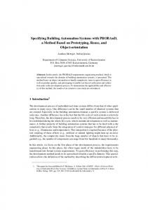
properties and properties to act upon, such as turning the ballasts on or off. We can further distinguish between hardware device drivers and software device drivers. Hardware device drivers consist of hardware modules with I/O ports and a micro-controller. The I/O ports are connected to physical devices, which usually possess no intelligence and are directly operated using electric signals, such as a lamp, a thermistor or the fan of an air conditioner. The micro-controller is responsible for driving those devices and exposing an interface that can be used to address each I/O port for reading and writing purposes. This hardware module can be connected to a computer, a network or to another hardware module [35, p. 523]. From a software point of view, reading from a sensor is equated with reading from a variable that represents a hardware input port and commanding an actuator is equated with writing a value on a variable representing an output port. Software device drivers consist of application programming interfaces used to enable other applications to interact with devices. These device drivers are used to (i) convert electric signals into values stored in variables or objects that can be read by software applications, and (ii) in contrast, they also convert values into electric signals that drive actuator devices. Overall, physical devices are mapped into I/O ports Overall, physical devices are mapped into ware device drivers, providing a higher level of abstraction, or to a software device driver that will act as an hardware abstraction layer, serving other software applications with the capability of operating those devices, without being concerned with low-level hardware-related details, such as device communication protocols. Fig. 1 illustrates this situation, where physical devices are connected to I/O ports of a hardware module (acting as a hardware device driver) capable of providing an interface that abstracts these connections. Such an interface is then used to connect the hardware module (and thus connecting the physical devices) to a network. On the other hand, software applications require an abstraction layer, provided by software device drivers, to operate those devices. The network device driver will implement the network's protocol stack, abstracting upper layers from communication specificities and exposing the hardware module's presence in the network. This is followed by the hardware module's device driver that will operate the module directly, providing a simpler interface to the upper layer, exposing the module's ports and mechanisms simplifying the tasks of reading and writing for those ports. Each port will have an associated device driver that will expose the device connected to that port and the corresponding operation mechanisms. Finally, high-level abstractions of these devices are created by defining objects that represent those devices and can be manipulated by software applications.
2.4. Device model Automation hardware is highly heterogeneous and should be abstracted in a way that enables software applications to be as independent as possible from the specificities of the hardware. With respect to a BAS, devices have two interfaces, an electrical interface, that defines how to connect the device to the rest of the system, and an application interface that enables other devices and software applications to interact with the device through exposed datapoints. A device driver is a component that controls devices connected to a system, while simultaneously providing a layer of abstraction that simplifies their operation. Each device driver corresponds to a particular type of device, meaning that a system having to support hundreds of different devices must install hundreds of device drivers. The considerable diversity of devices available poses a challenge to the creation of a generic device driver that fits every device of the same type, i.e., devices that have compatible interfaces. The interface of one device is said to be compatible with another if some of the properties of one interface exist in the other and share the same data type. For example, a common device driver controlling every lamp device where all lamps have the same
2.4.1. Datapoints Datapoints, endpoints, tags or points have different definitions across the literature [12, p.54,13, Section 3.61]. However, they all describe entities as an addressable point of interaction between the control system and its domain objects [11]. Datapoints can be physical or virtual. A physical datapoint is directly related to a device connected to the system, such as a device's I/O ports (where each port can be mapped to a datapoint) [6, p.10]. In contrast, a virtual datapoint acts as a way of addressing virtual objects such as services provided by devices, for example, a temperature sensor exposing a datapoint that when read, returns the average temperature measured in the last hour, or a datapoint addressing a configuration parameter of a given device, in a way that writing to that datapoint affects the associated configuration parameter [36,37, Section 2.7.2]. Virtual datapoints can also be used to address stub devices for testing purposes. Every datapoint has metadata associated with it, which describe a set of rules for the interaction with that datapoint, where we can typically find the access type, the data-type, installed location, influence zone and a value update rate for reading and writing operations.
4
P. Domingues et al. / Computer Standards & Interfaces 45 (2016) 1–12
Fig. 1. Illustration of a Building Automation Hardware and software stack. Physical devices are connected to an I/O module, responsible for exposing them as addressable entities (on the left). The corresponding software representation of the hardware stack, where the I/O module is operated by a software device driver, exposing each port and each device connected to it (on the right).
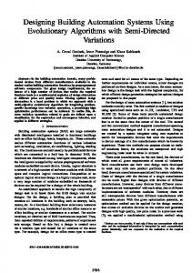
Datapoints offer one of three types of access: read, write, or both. Readable datapoints are read-only and usually relate to sensor devices. Writable datapoints are write-only and relate to actuator devices—writing to datapoints equates with updating the system's state. Datapoints that offer both access types may be used to write updates into a device, such as turning it on, and to read the device's internal state from it, for example, to probe the device on/off status. Datapoints that provide a read-access type should ensure a regular value update rate so that every client application knows how often it should poll that datapoint for value updates in a given period of time, which is known as smallest sampling interval. On the other hand, datapoints that support writing operations may provide a maximum rate at which writings can be performed. For instance if a lamp device and its associated writable datapoint are changed too frequently, hardware damage may occur. In addition, datapoints may expose only their new value when a significant change of value (CoV) occurred. In addition, datapoints have a data-type associated to them, which tells client applications how the information is structured when they read from a datapoint and how it must be structured when writing to that datapoint. Moreover, data-types can have semantic information associated with them, usually represented by a unit, which in turn describes what that structured information represents for a given domain context. For instance, a datapoint's value can represent a binary quantity, which is unitless, or a temperature in Celsius, a percentage, an applied force in Newton, among others. In some systems, datapoints having the same data-type can be linked together in a process known as binding. This means that when a datapoint is updated, linked datapoints are notified and may perform an action, such as obtaining the same value. A practical example of binding is a switch device that has its datapoint—representing the switch status—bound to a lamp device's datapoint. When the switch is pressed the lamp device turns on or off accordingly (Fig. 2). Non-virtual datapoints always belong to devices which are installed in a physical location of a building. Knowing the installed location of a datapoint is important, especially if that datapoint belongs to a sensor device. Conversely, datapoints also have a zone of influence, i.e., the space affected by their actuations, which may not be the same as the installed location. For example, a heating, ventilating, and air conditioning system
(HVAC) usually occupies one room in the building and affects several other rooms, while a lamp device affects the same room as it is installed in. 2.4.2. Commands Operations that can be executed on devices are called commands. When successful, commands cause devices to change their internal state or to actuate in their environment of influence. For example, setting the intensity of a lamp is the result of executing the command “dim to level”. Commands have parameters specifying what operation should be conducted, and attributes specifying how it should be carried out. The command that dims a lamp to a given level requires specifying the target value for the intensity parameter or ramp-up time. Commands can be sent to devices individually or in group if all devices of a group can accept that command. 2.5. Functionality In this section, we present the basic functionality that, based on several literature references and standards, it is essential in modern BAS [25]. Table 1 groups the functionalities described in two international standards of reference in the following categories: Grouping and Zoning, Event Notification, Alarm Notification, Historical Data Access, Scheduling, and Scenarios. 2.5.1. Grouping and zoning A device group is a logical identification of a set of devices. There are two fundamental types of groups: device collections and command
Fig. 2. Representation of two datapoints bound together, where the switch device's datapoint notifies the lamp device's datapoint of status updates.
P. Domingues et al. / Computer Standards & Interfaces 45 (2016) 1–12 Table 1 BAS functionalities addressed in ISO 16484-3 [25] and EN 15232 [26]. †This aspect is mentioned throughout the document EN 15232. Functionality
ISO 16484-3
EN 15232
Grouping/zoning Individual zone control is The concept of zones is used to listed as a required define room or zone specific functionality. (Section 5.1.1.4) control activities and setpoint preferences. (p. 27, 32, 46) Event Event handling and Refers to the notification of notification notification are described as changes in the system's status an operator function provided changes for several purposes by the HMI. (Section 5.1.1.2, such as controlling indoor 5.3.5.17) occupation.† Alarm Alarm notification is described Alarm notification are notification as an operator function essential to detect malfunction provided by the HMI. situations.† (Section 5.1.1.2, 5.3.5.17) Historical data This standard presents data States that data collection and access archiving and the means for logging are features offered by retrieving that data as building management management functionalities of systems. (p. 10) a BAS. (Section 5.3.2.9) Scheduling Provides a section describing Specifies the use of schedules time scheduling features. to control some attributes (Section 5.3.5.15) such as the air flow in a room (Section 7.5.1) Scenarios There is no direct reference to The standard defines several the “scenario” terminology, system operating modes that although, energy are used to adapt the management services are seen operation of the building to as a requirement that occupants' needs. Each according to EN 15232 operation mode can be benefits from this concept. modeled as a scenario.† (Section 5.1.1.3)
groups. Device collections consist of a set of devices used to organize or structure large installations. For example, “all devices in hallways” could perhaps consist of all luminaries and occupancy sensors of hallways. Command groups are collections of devices with compatible interfaces that are intended for simplifying commanding multiple devices at once. Interfaces are said to be compatible if they recognize the same commands or expose the same type of datapoints. Consider two interfaces, one for controlling a lamp and other for a HVAC system. If they both accept the commands on and off, they are said to have a degree of compatibility with each other, where the “on” command will light the lamp and turn the HVAC on, and the “off” command will switch both devices off. Device groups can be defined by hardware or by software. A hardware device group is a group created by the use of a hardware device module that abstracts several devices into just one device. For example, an air conditioner capable of measuring temperature and ventilating the air can be an abstraction of two independent devices, one being a thermistor and the other a fan. Software device groups have a major advantage over hardware device groups in that they can be dynamically arranged in order to add or remove members without requiring any effort modifying the system's structure, whereas hardware device groups would require hardware modifications or network restructuring. Groups of devices gather devices that are supposed to be commanded together with a given purpose. The group will thus behave as a virtual device whose properties can be assigned; assigning a property of a group will propagate that assignment to each device belonging to that group. A group can be “all lamps in corridors” that are to be commanded together in some situation. These groups are closely related with the concept of zoning. Building automation is intrinsically related to the idea of controlling spaces, since most actuations are confined to specific spaces. We can say that spaces are divided into several sub-spaces, known as zones. A zone can be a floor, a room (or just part of it) or an area within another zone. Zones may be related according to containment and adjacency, providing information about the building (for example, to identify and distinguish
5
halls from rooms in a building). Furthermore, a zone is characterized by metadata such as the zone name, space usage profile and location within the parent zone as well as its boundary polygon that defines the zone's shape and borders. Arranging spaces into zones helps commissioning the BAS and eases the task of the user in understanding, navigating and recognizing the controlled area in a user interface software. Zone information is also useful for querying spatial aspects of devices, such as where the devices are installed and their influenced environment.
2.5.2. Events and alarms An event consists of any occurrence that modifies a system's state (a door that opens or a lamp that turns off). The user of the BAS may choose to be notified of certain events, usually conditions that have been verified, such as a room's temperature that has changed two degrees Celsius since the last measurement, a specific door that has just opened, or a new person who has entered a room [13]. Alarms, on the other hand, are exceptional events generated by the system's operating conditions. Typically, alarms correspond to exceptional conditions originating in a specific device or a group of devices. Alarm events capture a malfunction of some device, lack of a resource essential for the execution of a process or a condition of the overall system's state that has to be pointed out. The information pertaining to an alarm indicates the apparent source of the problem and may also indicate when the originating alarming condition ceases. Alarms have severity conditions associated to the degree of disruption of the related object's normal operation. In contrast with regular events, alarms also have an acknowledgment process: either they require manual acknowledgment or may be transient, meaning that they are cleared whenever the condition that initiated them is no longer verified [13].
2.5.3. Historical data access Logs are essential to understand the activities of complex systems, particularly in the case of applications with little user interaction in BAS. Data logging is the process of recording commands sent to devices, devices' state transitions and events (such as alarms), in order to understand system activity and for diagnostic purposes. Logs may contain information about events, processes, alarms and user interactions [25]. Log records can be split in two categories: temporary and permanent. Temporary records are relevant in a short period of time after their occurrence, and after that period they can be removed. Permanent records must be kept for the entire life-cycle of the system. It is important to note that the preservation of permanent records is very demanding in terms of storage. For that reason, it is important to intelligently select what information should be stored permanently, the sampling rate and possibly the usage of data compression techniques. Data analysis is a useful functionality built atop of data logging systems, enabling the extraction of relevant information such as energy consumption and performance forecasts [38].
2.5.4. Schedules The BAS is often required to execute certain tasks according to given schedules. This is achieved by providing a scheduling service in order to associate task execution—commands sent to devices—with some moment in time. Schedules are uniquely identified by the combination of their date, time and the tasks being performed. They can be defined according to fine-grained units of time such as days, hours, minutes or even seconds. As time passes, scheduled commands are executed. Scheduled events can be one-time events or repeatable events. For convenience, the system should support the creation of several schedules; for example, two schedules used to manage the building's illumination in the winter and summer. Schedules are embedded in hardware controllers, but in larger facilities they are often configured in the main server that runs the BAS software [10].
6
P. Domingues et al. / Computer Standards & Interfaces 45 (2016) 1–12
2.5.5. Scenarios A scenario describes the desired status of a device or a group of devices associated to some context (such as the time of day or occupancy rate), relative to one or several zones. Scenarios can be static or dynamic. A static scenario does not change the state of devices once it is set, meaning that it does not prescribe actuation whenever environment conditions change. A static “studying scenario” can be defined as having the lights on over the table. The “TV scenario”, in turn, would switch off all luminaries so that the occupant could watch TV comfortably, and provide a dimmed ambient light near the corridor. Thus, activating a scenario amounts to setting the devices to the respective pre-set parameters defined in the scenario. In contrast, a dynamic scenario describes how the system reacts according to changes in the environment. A dynamic “studying scenario” specifies that lamps have to be turned on if there is not enough light. Implementing dynamic scenarios may become complex when they vary according to occupants' preferences. This is especially true when considering the preferences of more than one occupant in a zone or taking into account multiple factors simultaneously such as energy consumption peak times, noise, temperature or humidity. Another important aspect of scenarios is the time dimension. Device parameters can be set in sequence having certain delays, i.e., when a scenario is activated the effect on the devices' status may not be immediate. Consider a “morning” scenario which specifies two actions: (i) in the 30 minutes before the first person is expected to enter the building, the heating system, which was previously turned off to save energy, should turn on in order to heat the building according to a given setpoint. (ii) Then, 30 minutes later, the building's main entry door gets unlocked so that people can enter while, hopefully, the building's temperature will be at the desired set-point. 3. Building automation technologies This section maps out the essential functionalities of a BAS to stateof-the-art BA standard technologies available in the market. This analysis is based on an extensive analysis of the information models of each technology specifications, studying how each information model of deals with the functionalities identified in the previous section. Information models represent, characterize and relate concepts of a given domain by abiding to a common domain model where applications can share information, from which low-level details regarding physical and network specificities such as device architectures and protocol data are abstracted. We analyze how the information models address fundamental BAS concepts such as grouping, notifying, scheduling, and commanding, among others. Although many standards enable implementing these functionalities through, e.g., model extensions, software plug-ins, extra hardware modules, we will only consider functionalities natively provided by the specifications of standards, which formally define how such functionalities should be implemented. Otherwise manufacturers are left with the responsibility of carrying out these functionalities, and having freewill for promoting closed proprietary solutions, thus hampering interoperability with other solutions, resulting in situations of costumer lock-in. 3.1. KNX KNX is a technology that emerged from the European Installation Bus (EIB), European Home Systems (EHS), and Batibus that resulted in the establishment, of the Konnex Association, in 1999. Later, in 2004, the KNX protocol was standardized as norm EN 50090 and, in 2006, KNX was recognized as the international ISO/IEC 14543-3 standard. KNX distributes control across devices through functional blocks. A functional block consists of a group of datapoints and a behavioral specification about the device, for example, a “binary push button” functional block representing the functionality of an on/off switch. Each
functional block can be associated with one device. Although a device must implement at least one functional block, it may have multiple ones. The KNX specification already defines standard functional blocks and datapoint types. A datapoint represents a functional block's inputs and outputs, and application parameters such as an internal variable storing the minimum light intensity that a lamp controller can provide. These datapoints have an address and data-types associated to them [39] and typically, devices communicate by writing to other devices' datapoints via group communication. Datapoints can be bound to other datapoints (thus joining a group), in order to notify other devices of updates in the system. When a datapoint value changes, the new value is propagated to all datapoints bound to it. The KNX specification defines three distinct ways of binding datapoints: free binding, structured binding and tagged binding with increasing levels of semantics. In free binding datapoints having the same type can be linked freely. Structured binding follows a certain pattern defined by the information model for linking datapoints based on devices' functional blocks. For example, a push-button must have its output datapoints linked to the input datapoints of the device it will control. Finally, tagged binding proposes that part of the datapoint's address should contain some information in order to highlight some aspects like the group the datapoint belongs to. This can be used to select datapoints of a given zone, where parts of those datapoints' addresses represent their location, thus tagged binding can be used to group datapoints or devices [40]. Scene control is also supported, having three distinct approaches: (i) Setting the scene conditions via a commissioning tool, (ii) Setting the scene conditions of the connected actuators and storing this scene as a scene number in the connected actuators, and (iii) by using a datapoint type called scene number [41]. A key feature of the KNX message protocol is its observer-patternbased mechanism of information exchange. Multiple observing bus devices are notified via a single multicast message of changes to data on a single source. This allows the easy creation of m-to-n relations, since the source is not a fixed device. Hence normal bus traffic is not transacted via point-to-point messages, but through so-called group communication. Therefore, special group addresses are foreseen, which enable a receiving device to decide if it is a member of such a group, and a received message can either be ignored or processed. KNX devices are commissioned by the Engineering Tool Software (ETS),1 that provides the user with a higher level of abstraction with respect to the system's configuration complexity. KNX has some limitations: its specification does not natively refer to historical data access features, event and alarm notification, task scheduling and scenario management features, giving each vendor free will to implement such functionalities at higher layers without following a base guideline. 3.2. LonWorks LonWorks, or Local Operating Network (LON), is a fieldbus protocol developed by Echelon Corporation as a generic open control network. Its objective is to support a wide range of distributed applications in various domains such as buildings, production lines, or transportation. In 1999, the underlying control network protocol entitled LonTalk has been standardized as the ANSI/EIA-709 and ANSI/CEA-709 standard. It is also available as the European standard EN14908 and as international standard ISO/EIC-14908. In LonWorks a network device is called a node. Nodes have a unique address and may implement multiple functional profiles. Functional profiles describe the application layer interface of a device in detail, i.e., its expected functionality, which includes its behavioral configurations and network variables. Network variables are datapoints exposed by a device to other devices in the network used to exchange 1 KNX Software Tools — ETS5: http://www.knx.org/knx-en/software/overview/index. php.
P. Domingues et al. / Computer Standards & Interfaces 45 (2016) 1–12
information. Every network variable has an associated data-type that defines units, scaling and structure of the data it contains. Network variables can be bound (if they share the same data type). Network variables usually follow well-defined rules defined in LonWorks Standard Network Variables Types (SNVT) specification [42], guaranteeing interoperability between LonWorks devices. For example, LonWorks specifies variable types responsible for carrying alarm notifications. An example of functional profiles is a device acting like a switch, implementing the Switch functional profile [43] that exposes an output network variable used to turn on or off other devices, for example, a lamp device. Then, that lamp device implements a Lamp Actuator functional profile [44], exposing an input network variable used to receive input values controlling the lamp's status. By binding these variables, the switch device will be able to command the lamp device. Functional profiles can also be a drawback since there is no way that the specification can foresee every need. Therefore it turns out that many manufacturers implement their own proprietary extensions, thus hampering interoperability. An example of a lack of functionality is the absence of network variables tailored for historical data access. However, similarly to other fieldbus standards, LonWorks can have programmable devices which may support such features not covered in the specification, unfortunately, at the cost of interoperability loss [45, p. 5–5, 5–6]. LonWorks supports the creation of logical virtual networks within the physical network structure's domains and subnets which can be used to implement zoning. Domains are used to separate large, independent groups of devices in a network, for example, separating lighting systems from HVAC systems. Subnets are physical or logical groups of devices within a domain. For example, a subnet can be a group of all devices of a room. Domains and subnets provide LonWorks with the capabilities of zoning. Inside subnets nodes can be addressed individually or by broadcasting. Another way to associate devices in a way that is independent of domain-subnet-node addressing is by creating a group. Groups are a collection of devices, where each member can communicate with others using the group's identification. Groups can also be used for broadcasting messages. 3.3. ZigBee ZigBee is a standard based on IEEE 802.15.4 specifying the network and the application layer. ZigBee enables devices to communicate wirelessly, reducing wiring costs and the aesthetic impact of the system's installation, providing a simple, low-rate, low-power and cost effective protocol for RF applications. ZigBee's information model is mainly defined across three layers that manage device objects, endpoints and bindings between those endpoints, known as the Application Support Sublayer, ZigBee Device Object and Application Framework layers [6]. The Application Support Sublayer is responsible for binding endpoints, message forwarding between bound devices, and the management of groups. Device groups are supported by group addressing where writing to a given address may result in writing to several devices. The ZigBee Device Object layer is responsible for overall device management, and is specifically responsible for defining (i) the operating mode of the device—telling if a device coordinates network communications or acts as an end device—, (ii) device discovery and determination of which application services the device provides (each application service corresponds to an endpoint of a device), and (iii) for handling binding requests from other devices or coordinators. Finally, the Application Framework is home to a device's applications. An application object tells what services the device can offer—for example, an application object can be a light bulb, a light switch, a LED, or an I/O line. Each ZigBee device can have up to 240 applications, thus 240 endpoints are reserved for this purpose in each device. To communicate with other devices applications make use of specific protocol data units called clusters that consist of predefined message structures consisting of commands and attributes, resembling an object in
7
object-oriented programming context [46, p. 238–239], that both communicating devices are aware of, thus providing interoperability. For example, an on/off cluster defines how to turn something on or off. This cluster is generic enough for working with light switches, pumps, garage door openers and any other device that can be switched on or off. ZigBee's cluster library provides clusters for managing device groups, scenarios, and alarm notifications [47]. 3.4. BACnet building automation and control networking protocol (BACnet) was developed by a project committee established by the American Society of Heating, Refrigerating and Air-Conditioning Engineers (ASHRAE). Its main objective was to provide a solution for BAS of all sizes and types. In 1995, BACnet was published as ANSI/ASHRAE 135 standard and later became a CEN and ISO standard within the ISO 16484 series [2]. Overall, BACnet defines an information model that organizes the system devices using a standard collection of objects [27]. These objects represent application services along their inputs and outputs, such as devices, calendars and schedules, commands, and control loops. In BACnet a device is represented by a device object which defines device properties like device model name, device vendor, device status and the list of other BACnet objects associated to the device. For example, a device with two analog inputs will have two instances of analog input objects associated [10, p. 243]. BACnet's model also accommodates proprietary object types for manufacturers to register functionalities not covered by standard objects, risking the interoperability between devices [54, p. 10]. BACnet supports grouping through a specific group object that consists of a list of objects belonging to a desired group and a list of the selected properties of each of those objects. Groups can be used to create logical groups such as zones. The BACnet's calendar object consists of a list of relevant dates (for example, public holidays or special events). On the other hand, schedule objects associate functions to specific dates, time or date intervals. Schedules can be periodic, if they are repeated every week or they can be a one-time event [55]. BACnet commands are used to write to several attributes of a group of objects simultaneously when invoked. These objects can be devices, calendars, inputs, outputs. BACnet commands can be represented as objects containing a list of actions that can be executed, where each action consists of a list of attributes of other objects to be changed along with their new values. For example, a command object can define a set of attributes to modify when a certain room is unoccupied and another different set of attributes when it is occupied, hence defining two possible scenarios for that room, one called “occupied” and the other called “unoccupied”. Also, it provides an object for logging and historical data access. The Trend Log Object acts as a monitor on the object values, storing each change in memory for further analysis. Developers can choose how much data they can hold in memory, by specifying how many values they want to keep. Another interesting BACnet feature is the notification class object used for distributing event notifications. These objects may require the recipient's acknowledgment and a list of recipients. The subscription of a recipient is maintained by a list of recipient device objects, associated with the notification object. BACnet provides neither concept of inheritance nor aggregation. Any model extensions must be made based on the creation of new standard objects. This lack of advanced modeling mechanisms makes data representation, such as sub-typing, difficult. [11]. 3.5. Other technologies Other frequently used technologies in BAS are EnOcean [8], Insteon [56], Modbus [57] and Z-Wave [58]. EnOcean and Z-Wave define low-
8
P. Domingues et al. / Computer Standards & Interfaces 45 (2016) 1–12
power wireless communication protocols and their inherent electrical aspects, and are usually employed in home and industry automation. Similarly, Insteon provides support for, but is not restricted to, wireless communication and is generally used for home automation. On the other hand, Modbus specifies an application layer messaging protocol for automation device communication (mainly focused on controlerto-controler message exchange), which can be implemented using several types of buses and networks (e.g., Modbus RTU, or Modbus TCP). However, these technology standards define mostly message transport protocols and do not specify interesting information models in the context of interoperability. Indeed the decisions regarding how device specific commands and top-level concepts (like scenarios or alarms, are carried out) are left open to the hardware manufacturers.
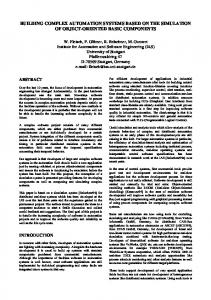
variability with intermittent power production that arises from an increasing adoption of renewables. Service Management Frameworks for BAS ease the task of maintaining the system, because changes in the automation software's internal logic will not affect any of its interfaces, and interfaces can be created or modified without affecting the automation software. Fig. 3 illustrates the typical topology found in management service frameworks, which abstract multipurpose client applications from the underlying automation technologies. In the following sections, we study the most commonly used service frameworks to tackle heterogeneity that have emerged from automation standards and have gathered ample support in the BA industry.
4. Management service frameworks
4.1. BACnet web services
Service-Oriented Architectures (SOA) or Service Frameworks describe architectural principles and patterns aiming at reducing dependencies between systems to ensure interoperability, sustainability and autonomy, through the abstraction of service [59]. Services are an abstraction of functionality available as a remote procedure call and service provider applications provide services to consumer applications. One key aspect of most SOAs is that service providers and consumers are loosely coupled. Service providers publish to a service broker server descriptions about their services, specifying each service's capabilities and invocation requirements. This service broker server manages a list of available service descriptions published by service providers, which can be requested by consumers. This action is usually known as service discovery. Service consumers must adapt to a specific interface in order to establish communication with service providers. SOAs are frequently used in building automation to integrate various types of technology, such as devices from a range of vendors or devices communicating using a diversity of protocols. Ultimately, a SOA acts as a communication gateway between system devices and client applications. Services can be reused by other applications that share the same interface guidelines as the service provider. Consider a BAS based on a SOA, where a service framework is responsible for encapsulating the logic of building automation and simultaneously for offering its services to enable any external application to interact with the system. These external applications may be graphical user interfaces for the automation system, thus enabling the development of multiple interfaces such as one interface for a desktop computer and another for smart phones. Moreover, this form of interconnection opens BAS to the world of the Internet of Things (IoT) with one of its manifestations being, for example, smart grids [60]. Here, information and communication technologies are an added guarantee of the grid's stabilit by coordinating demand
The BACnet specification also covers a high-level SOA protocol, concerning a client-server communication protocol oriented to the needs of building automation systems, known as BACnet/WS. This protocol provides a WS interface that can be used to communicate with multiple fieldbus networks [61,49]. BACnet/WS services are used for reading and writing data into the servers which can be directly connected to a fieldbus network. These servers are organized by an information model consisting of hierarchically arranged nodes, where nodes are used to map BAS domains. Nodes can only have one parent node, but can have an infinite number of children nodes. Nodes are described by their attributes, like node type, display name, value, and units, and these attributes can have nested attributes. Some node attributes are optional while others are always required (like the value attribute, for example). BACnet/WS provides two types of nodes: Standard nodes and reference nodes. Standard nodes contribute to the server's hierarchic model by naming part of the path to each leaf node (where leaf nodes are nodes with no children), i.e., the path to a leaf node is the composition of all standard nodes belonging to that leaf's path. Reference nodes are, as their name suggests, links to other nodes. These nodes are used to allow other nodes to appear in different places in the same hierarchic model. Each BACnet/WS server instance can only have one hierarchic model, meaning that every concept must be a child of the root node [49,62]. BACnet/WS defines different types of service, where the most frequently used are: the options services, the read services and the write services. The options services are used to modify the server's behavior. For example, changing the precision of retrieved values, or the server's default localization (important for localized attributes like multilingual names and the server's time-zone). Read services provide several ways of reading values from nodes' attributes, which can go from reading particular attributes, to reading an array of attributes with just one
Fig. 3. Typical topology of a Management Service Framework abstracting multipurpose client applications from the underlying building automation technologies.
P. Domingues et al. / Computer Standards & Interfaces 45 (2016) 1–12
request. In contrast, writing services provide a way of writing values into those attributes, individually or in group.
9
OPC UA defines an extensive list of service sets [64], where the more relevant are the discovery services, node management services, view manipulation services, querying and attribute services, method services, and monitored items and subscription services.
4.2. OPC 4.3. oBIX Object Linking and Embedding for Process Control (OPC) is an industry standard for defining a standardized mechanism to access automation hardware such as sensors, actuators and controllers, as well as associated services such as data logging and event notification subscriptions [53]. OPC is based on the idea that each vendor provides OPCcompatible drivers for their network devices. These drivers abstract OPC systems from dealing with the intrinsic specifications used by each vendor's devices. In this way every device can communicate through OPC's uniform data representation [27]. At its core, OPC conceptual model rests on two generic concepts: nodes and references. Every OPC object is a node, and every node may have references to other nodes [63,53, p. 22]. Each node has unique identification and a class type telling the purpose of the node. Nodes may represent objects, types, variables or even methods. Each node has a display name which is a human-readable localized text describing the object. References capture relations between nodes and are associated with a Reference Type object that defines their semantics. The most common types of these references are inheritance and composition. References between two nodes can be asymmetric (implying different roles for each node, such as an inheritance reference) or symmetric (implying similar roles for both sides). Reference types may also have references between them, thus supporting sub-typing through the use of subtype reference types [53 Fig. 2.5]. In sum, OPC defines a meta-model consisting of 8 standard classes of nodes, where the most relevant are: objects, variables and methods [50, p. 82]. Objects are a kind of node used to structure the system's domain, known as address space. They do not contain any information other than the attributes inherited from nodes. Object values and behaviors are exposed using variables and affected by invoking methods. Moreover, methods and variables are connected to an object by the use of references. There are two types of objects: simple and complex. Simple objects are used to define semantics, usually in order to organize other nodes; they have neither variables nor methods. Complex objects expose some structure of nodes beneath them, composed by variables and methods, which are present on each instance of these objects. Every object node is related to a node called object type, defining the object's type [50, p. 83]. Objects can also be marked as event sources which trigger events given certain conditions. Clients can subscribe to these events so they get notifications every time they occur through the subscription services. Comparable to objects, variables can also be simple and complex. Simple variable types only define the semantics of a given property, whereas complex variables expose some structure of more variables beneath it. All variables have an associated data-type and a value attributed to it. The data-type indicates the type of value held by a variable. OPC specification defines approximately forty standard data types [64, p. 60], and new ones can be added. Variables can be marked as historizable, meaning that the variables' values will be recorded into a log registry with a pre-defined sampling rate. Clients can subscribe to variables' value changes, so that they receive notifications about a variable's progress. Although OPC is flexible enough to model different domains other than building automation [65], it is also complex, therefore its specification may be hard to understand, extend and support. Due to this complexity, there is a lack of updated free-software and development tools [11]. Moreover, many tools are unable to implement the entire specification.2
2
OPC servers, http://www.opcconnect.com/freesrv.php.
oBIX is a platform independent model designed to promote device interoperability through web-services [12]. oBIX implements a SOA with three services used to read and write data, and to perform procedure calls (invoking operations, in oBIX terminology). The reading service is supported by every object in oBIX, writing is only supported by writable objects, and invoke is only supported by oBIX operations. The inputs and outputs of each service's request are specific to the target object or operation. The oBIX information model consists of typed objects, described by attributes. These objects are identified by their name and a Unified Resource Locator (URL) used to describe the object. oBIX models can be extended through object composition and inheritance. The oBIX specification describes a mapping into XML, where each object corresponds to exactly one XML element and attributes are represented as that element's XML attribute. The oBIX specification also defines default objects, which correspond to the XML's primitive element types such as string, real and Boolean. Some primitive elements have additional attributes such as minimum and maximum values, units and precision. There is no provision for devices, zones, groups or controllers in oBIX's specification, as these concepts must be manually defined. oBIX defines history records, events, and alarms services. The history record service consists of an interface that when implemented by any oBIX object, turns this object into a historical (traceable) object whose attributes will be stored. This interface exposes properties such as the maximum number of history records to maintain for an object, and the timestamps of the first and last records, among others. To manage events, oBIX provides a watch object, that implements a cache for storing events where clients can register several object attributes whose changes are to be tracked by the watch object every time they happen. Alarms are objects capable of generating events when some conditions are met. These conditions usually consist of some object's attribute whose value just went out of its defined bounds (for example, an object with an attribute called “temperature” whose bounds are 0 and 70, in which its current value is less than 0 or greater than 70). Alarms have to be associated to watch objects in order to keep track of recent alarms and send them to the client each time it polls the server. oBIX specifies services to query, watch, and acknowledge alarms. 5. Discussion The previous sections analyze the main BA technology standards aiming at understanding the extent to which their information models cover BAS concepts and functionality. Tables 2, and 3 summarize the analysis made concerning these technologies organized in terms of functionality coverage of the official standards specifications. It becomes clear that no single BA solution specification provides all the functionality prescribed in the international reference standards ISO 16484-3 [25] and EN 15232 [26]—although BACnet comes close to full coverage of functionality. A direct consequence of this fact is that, to get all the desired functionality in a complex infrastructure, more than one technology is required and the integration of distinct technologies can easily become a very complex undertaking [27,39]. BAS technologies have several concepts in common (such as Datapoints, Groups and Zones), however they are defined and implemented differently. For example, depending on the technology, Zones can be represented through address-groups or objects listing all the devices in a given physical area. Despite the complexity, integrating distinct technologies is possible to certain extent. For this reason, several solutions based on gateways have been developed and deployed.
10
P. Domingues et al. / Computer Standards & Interfaces 45 (2016) 1–12
Table 2 Mapping of how the analyzed technologies support the standard application concepts. Each row describes how a given technology implements each of the applicational concepts (according to its official specification). Technologies Functionality Grouping/zoning
Event notification
BACnet
Group communication objects [10, p. 245]
KNX
Group communication type [40, Section 4.2, 4.5]
Notification object Event object type and Provides trend log object Calendar and type [10, p. 248,249] services for alarm notification as a standard object [2] a Schedule [10, p. 243,244,254] object types [10, p. 241,250] Datapoint updates N.A. N.A. N.A. are usually broadcasted throughout the network [3]
LonWorks
Domains and subnets enable the creation of groups and zones [48, Chapter 3] Network group addresses and clusters are used to manage groups [47, Chapter 3.6] [6] Devices can be logically grouped using the model's hierarchy [49]
ZigBee
BACnet/WS
OPC UA
oBIX
Although OPC does not define the concept of grouping, objects may be used to aggregate other objects [50, p. 75] oBIX objects may aggregate and reference other objects [12, Chapter 8]
Provides SNVTs to handle events [42]
Alarm notification
Historical data access
Provides SNVTs to model alarms [42]
Reports events using The Alarms cluster can be a specific command used for sending and [6, Section 3.4.9] configure alarm notifications [47, Chapter 3.11] Provides services to Provides services to subscribe to alarm notifications [49] subscribe to event notifications [49]
Monitored Items offer ways to subscribe to event notifications [51, Section 5.12] Watch objects enable a client to subscribe to objects' state updates [12, Chapter 11]
Scheduling
N.A.
Provides an SNVT to schedule events [42] N.A.
N.A.
Historical data can be requested using the getHistoryPeriodic method [49, Section N.12.9] Defines an Information Model OPC tracks changes in for Conditions and Alarms variable attribute's with acknowledgment values and in the capabilities [52, Chapter 4] system's address space [53, Section 2.11] Supports the definition of Traceable objects have alarms with attributes which are acknowledgment. Alarms stored by the history have to be associated to record service [12, watch objects [12, Chapter 13] Chapter 14]
A noteworthy remark is that BA technologies such as LonWorks, BACnet, ZigBee and KNX have been designed to see their functionality extended by the use of specific additions, such as adding task scheduling and alarm notification capabilities through programmable devices (see for example, [45, p. 5–5,5–6]). In practice, however, manufacturers' devices can only interoperate if they implement their extensions having the same guidelines into account, which is not always possible due to the limitations of the current standards for covering the needs of a BAS. Therefore, it is often the case that these devices use custom-made proprietary extensions that severely impair interoperability since they are not part of the standard specification. One example is the implementation of the proprietary TAC's network variables over the LonTalk protocol [66], which consists of a proprietary custom extension to the original LonWorks specification. The BA community has then pursued a solution for the problem of interoperability at a higher level of abstraction. Service Management Frameworks have thus emerged as integration solutions. As it can be
Scenarios Command objects may be used to emulate the scenario concept [2]
Can be implemented by different Datapoint Types related to Scenes (e.g. DPT_SceneNumber, DPT_SceneControl) [41, Section 4.19] Provides SNVTs to manage scenarios [42]
Scenes cluster enables setting up and recalling scenarios [47, Chapter 3.7]
N.A.
N.A.
N.A.
N.A.
N.A.
N.A.
grasped from Table 3, they do not provide a common domain representation containing all the required concepts. OPC, BACnet/WS and oBIX were designed to target interoperability between systems by defining a common domain model and a service abstraction layer, but they still miss some basic functionality. As a result some concepts are not be mappable and thus cannot be interoperated. Nowadays, interoperability is being put forward as the main challenge not only for BA but also for IoT technologies [67,22–24]. Much like in BAS, two levels of interoperability are distinguished in IoT applications: technical and semantic interoperability [68]. Technical interoperability concerns with the translation of messages from one protocol to another, which is usually performed by the so called network gateways. In contrast, semantic interoperability relates to how top-level concepts from different technologies are interchanged, understood and processed. The upsurge of interest in the IoT has created a profusion of new device manufacturers which, develop their proprietary solutions resulting in increased heterogeneity—in the sense that each IoT device
Table 3 Comparison of the coverage of functional aspects by the studied technologies. Legend: ○ low or no support ◐ medium or partial support ● high or full support. Functionality
Grouping/zoning Event notification Alarm notification Historical data access Scheduling Scenarios
Building automation technologies
Service frameworks
BACnet
KNX
LonWorks
ZigBee
BACnet/WS
OPC UA
oBIX
● ● ● ● ● ◐
● ● ○ ○ ○ ●
● ◐ ◐ ○ ● ●
● ● ● ○ ○ ●
◐ ● ● ● ○ ○
◐ ● ● ● ○ ○
◐ ● ● ● ○ ○
P. Domingues et al. / Computer Standards & Interfaces 45 (2016) 1–12
communicates using its own proprietary protocol3,4. Overcoming heterogeneity seems to be a moving target.
6. Conclusions This article systematizes fundamental aspects of BAS, contributing to a common understanding of fundamental building automation concepts aligned with the well known standards ISO 16484-3 and EN 15232. Using these standards as guidelines this work highlights the scope of the functionality that should be expected from the typical BAS. Another contribution of this work is the assessment of the industry's standard building automation technologies in terms of functional requirements employing a uniform terminology. Moreover, the study also provides a detailed mapping of features between existing technologies, according to their official specifications, and identifies their functionality gaps. It becomes clear that no single technology is able to cover all the functionality expected from a BAS, thus requiring posterior, custom made, feature developments—a state of affairs that, presumably, is among the main causes of heterogeneity in building automation. Despite the fact that the BA heterogeneity problem is amply recognized in the literature, its extent has never been characterized against the standards currently in effect. The impact of comparing solutions with respect to functionalities according to literature standards is thus far reaching. On the one hand, this study sets the stage for a better understanding of the features and limitations of BA technologies. On the other hand, our systematization of exposed functionality also equips integrators, developers and manufacturers with vendor-independent knowledge of requirements for BAS technology, easing the task of understanding and integrating different solutions. Overall, no solution exists that is capable of providing the full breath of BA functionality. In the meanwhile, a profusion of ad-hoc solutions and technology standards that compete to be the lingua franca keep arising in the IoT.
Acknowledgments The work of INESC-ID authors was supported by national funds through FCT (Fundação para a Ciência e Tecnologia), with references UID/CEC/50021/2013 and EXCL/EEI-ESS/0257/2012 (DataStorm). Access to automation technologies was facilitated by IST in the scope of the SMARTCAMPUS EU project. The work of TU Vienna was partially carried out in the context of research regarding IEA-EBC Annex 58 (supported by Austrian Research Promotion Agency under the project number P- 843156).
References [1] M. Brambley, D. Hansen, P. Haves, D. Holmberg, S. McDonald, K. Roth, et al., Advanced sensors and controls for building applications: market assessment and potential R&D pathways, PNNL-15149, Technical report, Prepared for the U.S. Department of Energy by Pacific Northwest National Laboratory2005. [2] ISO 16484-5, Building automation and control systems (BACS) — Part 5: Data communication protocols, 2014. [3] ISO/IEC 14543-3-1, Information Technology — Home Electronic Systems (HES) Architecture — Part 3-1: Communication layers — Application layer for network based control of HES Class 1, 2006. [4] ISO/IEC 14908-1, Information Technology — Control Network Protocol — Part 1, 2012. [5] MODBUS, Application Protocol Specification V1.1b32012. [6] ZigBee Alliance, Inc., ZigBee Specification, 2008. [7] IEEE 802.15.4, Standard for Local and Metropolitan Area Networks, 2011. [8] EnOcean GmbH, EnOcean Serial Protocol 3 (ESP3), 2014. [9] ISO/IEC 14543–3-10, Information Technology — Home Electronic Systems (HES) — Part 3–10: Wireless Short-Packet (WSP), 2012. 3 Internet of Things Protocols & Standards: http://postscapes.com/internet-of-thingsprotocols. 4 IoT in Protocol War: http://www.eetimes.com/document.asp?doc_id=1325114.
11
[10] H. Merz, T. Hansemann, C. Hübner, J. Backer, V. Moser, L. Greefe, Building Automation: Communication systems with EIB/KNX, LON and BACnet (Signals and Communication Technology), Springer, 2009. [11] W. Granzer, W. Kastner, Information modeling in heterogeneous building automation systems, Proceedings of the 9th IEEE International Workshop on Factory Communication Systems, 2012. [12] T. Considine, B. Frank, OBIX Version 1.1 — Committee Specification Draft 01, Public Review Draft 01, Technical report, OASIS Open Building Information Exchange TC2011. [13] ISO 16484-2, Building automation and control systems (BACS) — Part 2: Hardware, 2004. [14] G. Clarke, D. Reynders, Practical modern SCADA protocols: DNP3, 60870.5 and related systems. Newnes, 2004. [15] F. Wu, K. Moslehi, A. Bose, Power system control centers: Past, present, and future, J Proc IEEE 93 (2005) 1890–1908. [16] S. Mackay, J. Park, E. Wright, Practical Data Communications for Instrumentation and Controls, Elsevier, 2003. [17] I. Fovino, A. Carcano, M. Masera, A secure and survivable architecture for SCADA systems, Proceedings of the 2nd International Conference on Dependability, 2009. [18] K.A. Stouffer, J.A. Falco, K.A. Scarfone, SP 800-82. Guide to Industrial Control Systems (ICS) Security: Supervisory Control and Data Acquisition (SCADA) systems, Distributed Control Systems (DCS), and other control system configurations such as Programmable Logic Controllers (PLC), Technical report, National Institute of Standards & Technology, 2011. [19] G. Zecevic, Web based interface to SCADA system, Proceedings of the International Conference on Power System Technology1998. [20] J. Lahti, A. Shamsuzzoha, T. Kankaanpaa, Web-based technologies in power plant automation and SCADA systems: a review and evaluation, Proceedings of the IEEE International Conference on Control System, Computing and Engineering, 2011. [21] G. Björkman, T. Sommestad, H. Hadeli, K. Zhu, M. Chenine, SCADA system architectures, Technical report, European Community: 7th Framework Programme, 2010. [22] J.P. Thomesse, Fieldbuses and interoperability, Control Eng Pract Vol. 7 (1) (1999) 81–94. [23] E. Finch, Is IP everywhere the way ahead for building automation? Facilities Vol. 19 (11/12) (2001) 396–403. [24] Armin Veichtlbauer, Thomas Pfeiffenberger, U.S., Generic control architecture for heterogeneous building automation applications, SENSORCOMM 2012: The Sixth International Conference on Sensor Technologies and Applications 2012, pp. 148–153. [25] ISO 16484-3, Building automation and control systems (BACS) — Part 3: Functions, 2005. [26] BSI: EN 15232, Energy performance of buildings — Impact of Building Automation Control and Building Management, Technical report, RHE/16, 2012. [27] A. Fernbach, W. Granzer, W. Kastner, Interoperability at the management level of building automation systems: a case study for BACnet and OPC UA, Proceedings of the IEEE 16th Conference on Emerging Technologies Factory Automation (ETFA), 2011. [28] P. Pallinger, L. Kovács, Ili: A framework for implementing smart spaces, ERCIM News2011. [29] J.P. Thomesse, Fieldbus technology in industrial automation, J Proc IEEE 93 (2005) 1073–1101. [30] D. Dietrich, T. Sauter, Evolution potentials for fieldbus systems, IEEE International Workshop on Factory Communication Systems, 2000. [31] M. Hawke, Introduction to fieldbus, Technical report, Moore Industries-International Inc., 2006 [32] IEC 61131–3, Programmable controllers — Part 3, 2013. [33] IEC 61499–1, Function blocks — Part 1: Architecture, 2012. [34] J. Sousa, R. Babuška, H. Verbruggen, Fuzzy predictive control applied to an airconditioning systems, Control Eng Pract 5 (1997) 1395–1406. [35] D.P. Bovet, M. Cesati, Understanding the Linux Kernel, O'Reilly, 2006. [36] E. Warriach, E. Kaldeli, J. Bresser, A. Lazovik, M. Aiello, Heterogeneous device discovery framework for the smart homes, Proceedings of the IEEE GCC Conference and Exhibition, 2011. [37] Echelon Corporation, LONMARK Application Layer Interoperability Guidelines, 2001. [38] S. Ramos, J.M.M. Duarte, J. Soares, Z. Vale, F.J. Duarte, Typical load profiles in the smart grid context; a clustering methods comparison, Proceedings of the IEEE Power and Energy Society General Meeting, 2012. [39] M. Neugschwandtner, G. Neugschwandtner, W. Kastner, Web Services in Building Automation: Mapping KNX to oBIX, Proceedings of the 5th IEEE International Conference on Industrial Informatics, 2007. [40] Konnex Association, KNX System Specifications, 2009. [41] KNX Association: KNX Advanced Course: Interworking. (Home and Building Management Systems). [42] Echelon Corporation, LONMARK SNVT Master List, 2002. [43] Echelon Corporation, Functional Profile: Switch, 1997. [44] Echelon Corporation, Functional Profile: Lamp Actuator, 1997. [45] Echelon Corporation, Introduction to the LONWORKS System, 1999. [46] R. Faludi, Building Wireless Sensor Networks with ZigBee, XBee, Arduino, and Processing, O'Reilly Media, 2011. [47] ZigBee Alliance, ZigBee Cluster Library Specification, 2008. [48] Echelon Corporation, LonTalk Protocol Specification, 1999. [49] ASHRAE — American Society of Heating, Refrigerating and Air-Conditioning Engineers, BACnet A Data Communication Protocol for Building Automation and Control Networks (Standard 135-2004 — ANSI Approved), 2004. [50] OPC Foundation, OPC UA Part 3 — Address Space Model 1.01 Specification, 2009. [51] OPC Foundation, OPC UA Part 4 — Services 1–2.01 Specifications, 2009. [52] OPC Foundation, OPC UA Part 9 — Alarms and Conditions 1.00, 2010. [53] W. Mahnke, S.H. Leitner, M. Damm, OPC Unified Architecture, Springer, 2009.
12
P. Domingues et al. / Computer Standards & Interfaces 45 (2016) 1–12
[54] David M. Schwenk, Stephen J. Briggs, D.M.U., J. Bush, Development of an open building automation system specification based on ANSI/ashrae 135-2004 (BACnet communications protocol), Technical report, US Army Corps of Engineers, 2007. [55] Chipkin Automation Systems, BACnet: The Schedule Object, http://www.chipkin. com/bacnet-the-schedule-object/2007 [Online; accessed 14-July-2014]. [56] INSTEON, Insteon Whitepaper: The Details, V2.0, 2013. [57] MODBUS IDA, Modbus Application Protocol Specification, V1.1b, 2006. [58] Zensys A/S, Z-Wave Protocol Overview, V2.0, 2006. [59] F. Jammes, H. Smit, Service-oriented paradigms in industrial automation, J IEEE Trans Ind Inf 1 (2005) 62–70. [60] O. Hersent, D. Boswarthick, O. Elloumi, The Internet of Things: Key Applications and Protocols, 2nd Ed Wiley, 2012. [61] ASHRAE — American Society of Heating, Refrigerating and Air-Conditioning Engineers, Proposed Addendum ar to Standard 135-2010, BACnet — A Data Communication Protocol for Building Automation and Control Networks, 2010.
[62] M. Neugschwandtner, G. Neugschwandtner, W. Kastner, Web services in building automation: Mapping KNX to BACnet/ws, Proceedings of the 5th IEEE International Conference on Industrial Informatics, 2007. [63] OPC Foundation, OPC UA Part 1 — Overview and Concepts 1.01 Specifications, 2009. [64] OPC Foundation, OPC UA Part 5 — Information Model 1.01 Specifications, 2009. [65] A. Maka, R. Cupek, J. Rosner, OPC UA object oriented model for public transportation system, Proceedings of the Fifth UKSim European Symposium on Computer Modeling and Simulation, 2011. [66] T.A.C. Vista, TAC Xenta Network Guide, 2001. [67] P. Desai, A. Sheth, P. Anantharam, Semantic gateway as a service architecture for iot interoperability, Mobile Services (MS), 2015 IEEE International Conference on 2015, pp. 313–319. [68] IERC AC4, IoT Semantic Interoperability: Research Challenges, Best Practices, Solutions and Next Steps, 2014.