CAAD MEETS DIGITAL PHOTOGRAMMETRY
Page 1
CAAD MEETS DIGITAL PHOTOGRAMMETRY - MODELLING “WEAK FORMS” FOR COMPUTER MEASUREMENT Urs Hirschberg Chair of Architecture and CAAD Swiss Federal Institute of Technology Zurich CH-8093 Zurich e-mail:
[email protected] André Streilein Institute of Geodesy and Photogrammetry Swiss Federal Institute of Technology Zurich CH-8093 Zurich e-mail:
[email protected] ABSTRACT The integration of state-of-the-art photogrammetric methods with the capabilities of CAAD has great potential for a variety of architectural applications. This paper describes the current status of an ongoing research project which aims to develop an easy to use tool for the photogrammetric generation of accurate, reliable and well structured 3D CAAD models of architectural objects. The project adresses the whole range of issues that arise from the digital image acquisition to the data processing, the data integration between photogrammetry and CAAD and the architectural structuring of the geometric data. While also giving a brief overview of the project, the paper concentrates on one central aspect of the system: a method to model what we will define as “weak forms” as the basis for qualitatively controlled computer measurement. 1. INTRODUCTION Nowadays surveying methods based on imaging sensors are used in many applications in computer vision, robotics, machine vision and industrial metrology. The hardware for these applications with powerful workstations on one side and digital imaging sensors on the other has become available and affordable over the past few years. In architecture these methods can be applied for the surveying and documentation of monuments or for the production of as-built plans for renovations or alterations. As photogrammetry generally records all data as a series of three dimensional coordinates, it makes a natural partner for today’s three-dimensional CAAD systems. Photogrammetry basically means measuring in images. Therefore a system for digital photogrammetry must be a hybrid, processing both image and vector data. This hybrid functionality can be employed in a great variety of applications. In monument preservation or archaeology it can be used to produce very detailed documentations in plans, images and database-records. In urban planning images can be interpreted in a much less detailed way to produce abstract yet correct and reliable 3D models of “city-scapes” useful as references to judge new projects. In some applications the production of traditional architectural as-built plans will be most important, such as for renovations or alterations of existing buildings for which no or only inaccurate plans exist. In the growing field of virtual reality on the other hand, the production of rectified texturemaps from perspective images is another application. It is important to mention this variety of uses, not only to show that digital photogrammetry is an Presented paper on ACADIA `95 "Computing in Design - Enabling, Caputring and Sharing Ideas", 19-22 October 1995, Seattle, Washington, USA. Published in conference proceedings (in press).
CAAD MEETS DIGITAL PHOTOGRAMMETRY
Page 2
interesting topic for CAAD, but also to explain why we pursued openness and general applicability as two of the key aspects in the design of our system. A number of commercial software packages useful for architectural photogrammetry are available on the market [1] [2]. As they are restricted to manual measurements, the accuracy of the delivered data is highly dependent on the dexterity of the operator. On top of that the application of these programs is usually quite time-intensive and requires special training. These shortcomings may account for the fact that these methods are still rather rarely made use of in the architectural practice. The system currently under development at the Swiss Federal Institute of Technology aims to overcome these shortcomings. It is a fully digital system for architectural photogrammetry not only in the sense that it transfers traditional photogrammetric techniques which usually involved very expensive mechanical equipment to a computer-terminal (which is, essentially, what the mentioned commercial packages do). Most importantly it takes advantage of the digital format of the data to increasingly automatize the time-consuming measurement process. These new semi-automatic measurement techniques create a need for a modelling strategy quite different from the one found in current CAAD systems. We refer to it as modelling “weak forms”. 2. SYSTEM 2.1. Overview The system aims to combine digital photogrammetry with the capabilities of CAAD. The photogrammetric processing is performed with a digital photogrammetry station (DIPS). Its advantage is the availability of semi-automated measuring procedures based on digital imagery. The main principle is that the human operator assumes responsibility of the image understanding part, while the actual measurement is automatically handled by the computer. The user indicates relevant parts of the object by approximating a geometric topology to it. The photogrammetric algorithm matches this topology with the image data of multiple images, thereby deriving its exact three dimensional position and geometry. The initial topology is generated in a CAAD environment.
Film-based Camera
Laboratory Processing
Digitization
Digital Images
Object Solid-state Sensor
Digital Photogrammetric Station CAAD System
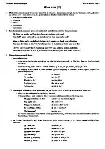
Figure 1: Digital Architectural Photogrammetry with DIPAD. By customizing the functionality of an existing software package with a true programming interface (AutoCAD) we achieved an increasing integration of CAAD and DIPS in the course of the project. Presently the integration of the datastructures and the consistency of the user interface has reached a degree of completeness to make it reasonable to refer to the system as one entire whole: DIPAD (Digital System for Photogrammetry and Architectural Design [3] [4]).
CAAD MEETS DIGITAL PHOTOGRAMMETRY
Page 3
2.2. Acquisition of image data The initial step in a photogrammetric process is the acquisition of image data (see Figure 1). While traditional film-based cameras still provide unsurpassed image resolution, today’s solid state sensors offer a number of advantages (on-site quality control, no subsequent digitization, low cost, etc.). We have been able to demonstrate that normal off-theshelf videocameras deliver image data which are reliable enough to produce sufficient accuracy for architectural purposes [5]. The comparatively poor resolution of the videocamera sensor can be compensated by high redundancy of information. An overview of existing systems for digital image acquisition is given in [6] [7]. 2.3. DIPAD: Integration of DIPS and CAAD A major question for the design of a system like DIPAD is how to set up the communication between the CAAD system and the photogrammetric system. While importing and exporting files between the two systems was the method used in the first prototypes, the integration of the two systems became more direct and powerful as the project went on. Presently it is possible to perform all the editing on the model in the CAAD system while the objects are projected run-time into the previously oriented images (see Figure 2). This means that DIPAD can make full use of the modelling capabilities of the CAAD program, getting instant feed-back about how closely the model matches the image. The photogrammetric measurement on the other side can include all the geometric and semantic information present in the CAAD system as constraints in the measurement process. Changes in the database of one system can be mapped onto the database of the other system instantly. So, modelling and measuring are smoothly integrated actions in one continuous work-flow (see Figure 3)
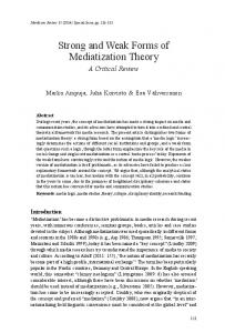
Figure 2: The modelling in the CAAD system can be entirely monitored in the DIPAD viewer linked to the model. Each camera icon corresponds to one viewer.
CAAD MEETS DIGITAL PHOTOGRAMMETRY
Page 4
Figure 3: CAAD and Photogrammetry systems communicate runtime: modelling and measuring are smoothly integrated actions in one continous work-flow. Some of these functionalities are of quite general usefulness for architectural modelling. The little camera-icons in the CAAD system (see Figure 2) are linked with corresponding cameraorientations of an image viewer. When the parameters of a camera-icon are edited in the CAAD system, the changes of its view can be entirely monitored in the viewer. This is primarily intended to facilitate the initial positioning of a camera with respect to the model (further refinement of the cameraposition is then done as part of the computer measurement). Moving around these icons can however also be used to do real-time fly-throughs in the model. This is quite effective especially because the analytical view of the model with the cameraposition is always visible concurrently. As the exact outer orientation of an image (cameraposition and viewing direction) is determined by DIPS, it is also possible to set up the exactly corresponding perspective in the CAAD system (see Figure 4). This greatly facilitates the production of montages. So the functions we are developping are not only relevant in creating a precise model of an existing building, they also serve well when creating new buildings in existing contexts or even as general feedback generators during modelling. As the essential aspects of the system, in this paper we will focus on the automated 3D feature-extraction procedure and the modelling functionality, which differs notably from conventional CAAD systems. This is due to the fact that the modeller must only supply the qualitative definition of the model, while the quantitative aspects are determined by photogrammetric means.
CAAD MEETS DIGITAL PHOTOGRAMMETRY
Page 5
Figure 4: AutoCAD perspective set up according to orientation of image.
2.4. Computer for measurement: 3D linear feature extraction Ultimately, the success of a digital system for architectural photogrammetry depends on its ability to automatically process images of varying complexity. The algorithmic complexity is highly correlated with the image complexity. Highly structured images require only simple algorithms for image analysis and vice versa. Images of architectural objects are very often of high complexity, so fully automated approaches are doomed to fail. Therefore one has to resort to semi-automated processing techniques. In order to establish feature extraction that provides for high precision as well as for reliability, a top-down strategy is chosen. The semantic object model is used to detect the features described by this model. Thus only relevant features are extracted and redundant information and data complexity are reduced to a minimum. Another advantage is that this approach acts globally. Small deformations (e.g. image noise, blurred image structures, etc.) in general do not affect the estimated result. The three-dimensional position of the object is derived by simultaneous multi-frame feature extraction, whereby the object model is reconstructed and used to triangulate the object points from corresponding image points. The geometric information of the object in the digital images is represented by locations and grey values of pixels. Looking at images taken for architectural photogrammetry it is evident that in most cases linear boundaries (edges) of an architectural feature contain more information than the vertices (corners) of this feature. Although edges are only a small percentage of the whole image content, they have major importance for the description of object discontinuities. The CAD-based 3D feature extraction routine takes advantage of this knowledge. It first locates the edges of the features to be measured and then derives the vertices as intersections of appropriate lines (see Figure 5).
CAAD MEETS DIGITAL PHOTOGRAMMETRY
Page 6
a.
b.
c.
d.
Figure 5: Example for Feature Extraction Algorithm. The position of the edge is then determined with subpixel precision by fitting a second-order polynomial in the direction of the gradient. The maximum point of the fitting curve corresponds to the subpixel position of the edge (see Figure 6). The covariance matrix of the estimated polynomial parameters represents the accuracy of the edge point. Besides the precision of the detected edge, another important aspect for the extraction of features is the significance of the detected structures. In architectural photogrammetry problems typically occur due to occlusion, illumination effects (e.g. shadow edges), features fading into background or varying background. In order to handle such cases and to exclude insignificant structures, the algorithm rejects all edge points which do not fulfill two criteria from the list of points contributing to the entire edge. The first criterion is that the orientation of the gradient does not deviate too much from the orientation of the entire edge; the second is that the magnitude of the gradient has to be higher than a user defined treshold. An example of the performance of these criteria can be seen in Figure 5. The occluding structure of the bush in the foreground does not disturb the estimation of points 11 to 14. But there are typically additional circumstances that may create corners in image space, which have no representation as a corner in object space (e.g. a T-junction is created if one object edge is occluded by another). The algorithm handles such cases by consulting
CAAD MEETS DIGITAL PHOTOGRAMMETRY
Page 7
Figure 6: Zoom of extracted image edge points (sub-pixel precision). the underlying semantic object model, which contains the necessary information about existing (“real”) object points. This image based feature extraction algorithm is performed sequentially in all images. The object coordinates of a point occurring in two or more images are calculated by a multiple-ray forward intersection, which treats the image coordinates as observations, the object coordinates as unknowns and all other parameters (elements of exterior orientation, interior orientation and additional parameters) as known constants. The calculated object coordinates are then projected, together with the semantic object description, into each image plane and used to restart the feature extraction algorithm. Figure 7 gives an example of the performance of this iterative procedure on a single feature in three images. A more detailed description of the feature extraction mechanism is given in [4]. 3. MODELLING 3.1. Human for interpretation: “reading” Architecture To interpret a scene qualitatively is something very natural for humans and - as the computer vision community knows - very difficult for computers [8]. It is therefore quite straightforward to leave the interpretation of the scene to the operator. But this is not the reason why we adopted a semi-automatic strategy which lets the computer as well as the human operator each do what they are best at. We do pursue increasing automation in the long run! However, it is necessary to keep in mind what automation of an interpretative process means. In the case of architecture not the least of problems that this interpretative process faces is that there are no accepted rules that could govern it. Interpreting architecture is by no means a well-defined task. One does not have to go to the more academic considerations Venturi [9] or Slutzky and Rowe [10] point out. The problem arises at a much more fundamental level [11]. While there are many accepted ways to structure a model and even some standards as far as the use of layers goes, there are hardly two CAAD operators that would build the same model in the same way. For good reasons. There are many tricks and techniques experienced CAAD operators know about that come into play depending on the sorts of tasks a model will be used for. Whether it is used for the production of plans only, whether it will be used for rendering later, whether it is necessary to disintegrate the model in certain analytical ways to show a design intent, or whether texture maps are to be applied in a rendering system - usually all of these considerations evoke a different approach by the CAAD operator. And then much of it is personal style. So apart from the fact that it is sim-
CAAD MEETS DIGITAL PHOTOGRAMMETRY
Page 8
(a.) part of a scene.
(b.) initial position of feature.
(c.) final position of feature.
Figure 7: CAD-based 3D Feature Extraction. ply difficult to automatically detect features, full automation of the interpretation of architectural images faces many other challenges. Our approach is therefore to provide a very general tool that allows for different user intents and styles in the modelling process. Automation could then come in as a computer learning mechanism, in a way that the operator can teach his individual modelling preferences to the system. Rather than trying to invent an arbitrary model structuring strategy that will fit all purposes as the basis for automation (it is highly questionable that such a universal strategy could indeed be found) we incorporate the accepted structuring means as options into the system. This was one of the main reasons for using a standard CAAD system as a platform for DIPAD. 3.2. Modelling with standard CAAD systems: an overview As mentioned above, rather than definitive rules for the structuring of CAAD models there are a number of functionalities and methods that standard CAAD systems offer to the user.
CAAD MEETS DIGITAL PHOTOGRAMMETRY
Page 9
Probably the first and foremost that comes to mind is the structuring in layers (incl. colors and linestyles). If it is applied efficiently this can be a very powerful tool as it allows for multiple groupings of the same element. The concept of blocks (types and instances) introduces hierarchies and higher level groupings. It allows fast modelling and testing of alternatives [12]. The concept of levels of detail (logical zoom) generates different modes of representation depending on the task [12]. These are the most important means of structuring a model and the most used ones in standard CAAD systems. Additional structuring can be achieved by extending the drawing database (different CAAD systems offer different options for this) or by linking an external database with the drawing database [13] (something which the more sophisticated CAAD system have introduced not too long ago). These methods are functionalities of basic usefulness and will be employed in different ways for different purposes and by different operators. All of them come into play when it is necessary to structure a model, whether it represents an existing building or a project. So all of them are offered as functionalities in DIPAD. 3.3. Modelling “weak forms”: the DIPAD modeller Standard CAAD systems offer many means of structuring a model that are independent of the metric of the model. But as for defining complex constrained geometric topologies they offer very little. Between the classic 2D polyline that only constrains all its vertices to one plane and the block, which - representing the other extreme - can only be scaled uniformly in x,y and z direction there is a big gap. This is, in our opinion, one of the reasons why even for experienced CAAD operators, it is still very difficult to design with the computer intuitively. The problem is not that the computer forces one to use metric categories from the very start. It’s the fact that dealing with these metric categories is part of any modification, as it is not possible to control them qualitatively to any reasonable degree [14]. Being able to define geometric models qualitatively rather than quantitatively would allow for a certain indeterminancy. This indeterminancy would certainly be helpful for designing efficiently. When preparing a model which represents the basis for the measurement of an existing building, however, it is an absolute necessity. For a project, the designer can arbitrarily fix all the measurements in his design. When preparing a model for computer measuring, though, the measurements are apt to be changed, they must be weak, otherwise no measuring can take place. Weak does not mean random, however, it means that a model offers a limited amount of geometric deformability, while maintaining some qualitative aspects of its shape. Weak models therefore are constraint-based models. These constraints can guide the computer’s measuring operations and ensure a qualitatively correct result. ‘Weak forms’ stands for controlled deformability and therefore allows for the possibility to disregard measurements when they’re not essential. Two main aspects differentiate modelling for DIPAD from traditional architectural modelling in CAAD: First of all the photogrammetric description is basically limited to what represents the visible surface of objects. While architectural plans (and therefore CAAD models) traditionally explain the construction of things, DIPAD can only measure and therefore will concentrate on modelling what is visible. This “superficial” approach may reflect the way some architects go about designing, but it is certainly not the most widespread let alone the only possible way to design. It is, however, well possible to describe buildings in terms of their surfaces. It is also possible to derive much information about the construction of objects from their appearance and to include this information by automatically making use of a knowledge-base.
CAAD MEETS DIGITAL PHOTOGRAMMETRY
Page 10
Secondly, while all the accepted means of structuring a CAAD model (layers, blocks, level of detail) are well applicable for DIPAD, the form of the models that are the basis for the computer measurement must be defined qualitatively rather than quantitatively. The fact that this weak form quality must only be provided for the modelling of the surfaces actually makes it much easier to achieve. It reduces the otherwise huge topic of weak forms essentially to one of complanarities, collinearities and proportions on the plane. While this is still rather complex, it is controllable well enough to allow easy user-interaction.
Figure 8: Partial view of the test object. The basis of the current DIPAD modeller is a set of functions that allow the definition of complex parametric objects for which complete rubberbanding functionality is supported. They overcome the limitations of xyz-scalability of traditional AutoCAD blocks and being entirely graphically editable make the modelling much more intuitive. They have been implemented making intensive use of AutoCAD’s extended entity data (EED), a facility that allows storing of additional data with the entity data of an object. When such a parametric object is generated or edited, its name and current parameters are stored in EED. The name serves as a reference to a knowledge-base. In this knowledge-base for every element a variety of information, most importantly a sort of genetic code, that contains a description in terms of points, lines, faces and parametric equations, is described. To edit these objects, special functions allow direct graphical interaction with all the specified parameters. They can, however, be edited with the standard AutoCAD commands as well. In that case they behave like standard blocks. These objects are available in a library. With the special functions, their insertion and editing can be entirely monitored in the external viewers. So even during the interaction with the model all changes become visible as projections overlayed on the actual image of the architectural object that is to be modelled and measured. As approximations to the actual positions are sufficient, this modelling is very intuitive and fast. Figures 8 - 10 show results of two recent test-runs with DIPAD. The image data used in the measurement were in both cases generated using a standard videocamera. The parametrization of the individual objects is what we refer to as internal constraints. The shape characteristics that can be controlled with the set of parameters are identical to the ways the photogrammetric procedures can adjust the element to better match the results of the 3D feature extraction. Without any qualitative guidance the accuracy of the measurement process creates unwanted results. For example four points that “obviously” lie on one plane (maybe the corners of a door) will be slightly offset. This creates unnecessarily com-
CAAD MEETS DIGITAL PHOTOGRAMMETRY
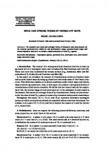
Point Model
Page 11
Wireframe Model
Digital Surface Model
Figure 9: Photogrammetrically generated CAD-Model of test object. plex and irregular models, even if the measurement actually reflects the physical condition of that particular door correctly. The user gets feed-back about the reliability of the extracted features by the underlying stochastic model. It is then possible to either select a different parametric object or to increase the level of tolerance. This way a user is always informed about the correctness of their assumptions as well as the precision of the model that is generated. In much the same way as internal constraints we plan to implement what we refer to as external constraints. Formulating external constraints means that constrained relationships between different objects, can be introduced by attaching or nesting the individual (parametric) objects to one another. Both methods, nesting as well as attaching, define a fixed geometric relationship between two objects: they can share an edge, have complanar sides or the like. Nesting an element also introduces a hierarchy in the model which can be used as a means to provide different levels of detail. 4. CONCLUSION In this paper we described the current and planned functionality of DIPAD, a system for digital architectural photogrammetry which brings together the functionality of CAAD and state-of-the-art photogrammetric computer measurement procedures. Pointing out briefly the many possible applications of digital photogrammetry in CAAD related fields as well
CAAD MEETS DIGITAL PHOTOGRAMMETRY
Page 12
Figure 10: Digital Surface Model in combination with Wireframe Model. as the main ideas and aspirations of the project, the main focus of the paper was the current integration of the CAAD and the photogrammetry systems. A central aspect of this integration is the development of the DIPAD modeller, which, built on top of an existing CAAD system, is designed to meet the special requirements of the photogrammetric computer measurement procedures. These requirements we paraphrased as “weak forms”. This term is currently also used in discussions about architectural theory. We adopted it and defined it for our purposes as “objects with controllable deformability”. Within DIPAD modelling weak forms is a very straightforward approach to guide computer measurement procedures qualitatively. In the broader context of modelling and designing in CAAD, the concept of modelling weak form is a contribution to the ongoing debate about designing with computers. 5. ACKNOLEDGEMENTS We gratefully acknowledge the support of ETH Zurich for this research project. 6. REFERENCES [1] [2] [3]
Fellbaum, M, “Low cost systems in architectural photogrammetry” Int. Arch. Photogramm. Remote Sensing, Washington DC, Vol 29, Part B5, pp. 771 - 777, 1992. Schenk, T, “Digital photogrammetric stations” Proceedings of 2nd Course in Digital Photogrammetry University of Bonn, Feb. 1995. Streilein, A., Beyer, H., Kersten, T., “Digital Photogrammetric Techniques for Architectural Design,” Int. Arch. Photogramm. Remote Sensing, Washington DC, Vol 29, Part B5, pp. 825 - 831, 1992.
CAAD MEETS DIGITAL PHOTOGRAMMETRY
[4]
[5]
[6]
[7]
[8]
[9]
[10]
[11]
[12]
[13]
[14]
Page 13
Streilein, A., “Towards Automation in Architectural Photogrammetry: CAD-based 3D Feature Extraction,” ISPRS Journal of Photogrammetry and Remote Sensing. 49 (5), pp 4-15, 1994, Streilein, A., Gaschen, S., “Comparison of a S-VHS Camcorder and a High-Resolution CCD-Camera for use in Architectural Photogrammetry,” International Archives of Photogrammetry and Remote Sensing, Vol. 30, Part 5, pp. 382-389, 1994. Luhmann, T., “Bilderfassung in der Nahbereichsphotogrammetrie - Aktuelle Tendenzen,” Vermessungswesen und Raumordnung (VR 54/8), Dezember 1992, WichmannVerlag Karlsruhe, pp. 400-410, 1992. Shortis, W.R., Snow, W.L. Goad, W.K., “Comparative tests of industrial and scientific CCD cameras using plumb line and test range calibrations,” International Archives of Photogrammetry and Remote Sensing, Vol. 30, Part 5W1, pp. 53-59, 1995. In this context one can refer to a variety of computer vision literature, as for example Uttal, W. R., On Seeing Forms, Hillsdale,NJ:LEA Publishers, 1988, or Nalwa, V. S., Computer Vision, Addison Wesley Publishing Company, 1993. But it’s just as interesting to study the non-technical approach of art theoreticians like Gombrich, E. H., Bild und Auge. Neue Studien zur Psychologie der bildlichen Darstellung. Klett-Cotta, Stuttgart, 1984. “While the second classification of complexity and contradiction in architecture relates to form and content as manifestations of program and structure, the first concerns the medium and refers to a paradox inherent in perception and the very process of meaning in art: the complexity and contradiction that results from the juxtaposition of what an image is and what it seems.” Venturi, R., Complexity and Contradiction in Architecture, Museum of Modern Art, 1966. “..., by this definition, the transparent ceases to be that which is perfectly clear and becomes, instead, that which is clearly ambiguous.” Slutzky, Rowe, Hsli, B. Hg.: Transparenz, Birkhaeuser Verlag 1974. “Computer technology is revolutionizing the way that architectural design is done, but the theoretical presuppositions underlying computer-aided architectural design systems are rarely made explicit and when they are, they often turn out to be shaky and inconsistent. There is an urgent need for a comprehensive, rigourously developed computational theory of design that can provide an adequate basis for practical software development work.” Mitchell, William J., The Logic of Architecture. Design, Computation, and Cognition, Cambridge, MA: MIT Press, 1990 The terms ‘types and instances’ as well as ‘logical zoom’ are used to describe fundamental methodologies that can be derived from the functionality of CAAD systems in L. Madrazo: “Design Education With Computers,” Proceedings of the CAAD futures ‘91 conference, Zrich, 1991. This functionality is used mainly to introduce facility management capability or GISlike functionality into CAAD. A description of an implementation of the latter type is given in B. Dave and G. Schmitt: “Spatial Data Environments”. Presented at the International Workshop on Advances in Geographic Information Systems - IGIS ‘94, Ascona, 1994. This deficiency has been pointed out in similar ways many times. It is used as an argument for the implementation of Geometric Reasoning and Variational Geometry in Wing, J. M., Arbab, F., “Geometric Reasoning: A New Paradigm For Processing Geometric Information.” report 85-144, Carnegie Mellon University, 1985, respectively in Light, R., Gosshard, D., “Modifications Of Geometric Models Through Variational Geometry.” Computer Aided Design vol. 14, pp 210-214, July 1982.