As a case study, the development of Acclaro--a commercial software system designed to aid designers who use axiomatic design -- is presented. This software ...
Axiomatic design of software systems N.P. Suh (1), S.H. Do Abstract Software is playing an increasingly important role in manufacturing. Many manufacturing firms have problems with software development. Software engineering is still labor- intensive and prone to errors. Industrial firms are under pressure to shorten the lead-time required in introducing new software, increase the reliability of their software, and increase their market share. Software must be designed correctly from the beginning to end. With this end in mind, axiomatic design theory has been applied to software design. This paper presents how the combination of axiomatic design has been combined with the object-oriented programming method to create a large software system. Keywords: software, axiomatic, design
1 INTRODUCTION Software and computers are playing central roles in manufacturing. Software controls manufacturing equipment, manufacturing systems, and the operation of the manufacturing enterprise. At the same time, the development of software can be the bottleneck in development of machines and systems, since current industrial software development is full of uncertainties, especially when new products are designed. Software is designed and implemented by making prototypes based on experience of software engineers. Consequently, they require extensive ‘debugging’ – a process of correcting mistakes made during the software development process. It costs unnecessary time and money beyond the original estimate. The current situation is caused by the lack of fundamental principles and methodologies for software design, although various methodologies have been proposed [1]. Application of axiomatic design to software was presented for the first time at the 1991 CIRP General Assembly [2] and the system design concepts presented in the 1997 CIRP General Assembly [3]. This paper includes many new concepts that are specific only to software design, which have been developed since then [4]. Software designed based on axiomatic design is selfconsistent, provides uncoupled or decoupled interrelationships and arrangements among ‘modules’, and is easy to change, modify, and extend. This is a result of having made correct decisions at each stage of the design process, i.e., mapping and decomposition [5][6]. The final design of software is represented by a flow chart that represents the entire system architecture of the software, which can aid software programmers. The flow chart can also be used as a management tool during the
software development phase [7][8]. It provides clear guidelines to software engineers engaged in a collaborative development effort and gives the order of execution of the resulting program. Extensionality and reusability at any level are guaranteed when the software is designed based on the axiomatic design theory. As a case study, the development of Acclaro--a commercial software system designed to aid designers who use axiomatic design -- is presented. This software is designed based on axiomatic design and implemented using a modified version of object-oriented techniques (OOT) and the Java programming language -- a platform independent language. The use of an OOT was necessary since the use of Java requires OOT. When AD is used, OOT can be considerably simplified. 2 AXIOMATIC DESIGN SOFTWARE SYSTEMS
OF
OBJECT-ORIENTED
Based on Axiomatic Design and object-oriented technology, we have developed a generic approach to software design. The software system is called ‘Axiomatic Design of ObjectOriented Software Systems (ADo-oSS)’that can be used by any software designers. ADo-oSS is a major new paradigm shift in the field of software engineering. It combines the power of axiomatic design with a popular software programming methodology called object-oriented programming technique (OOT) [9]. The goal of ADo-oSS is to make the software development a subject of science rather than an art and thus reduce or eliminate the need for debugging and extensive changes. ADo-oSS utilizes the systematic nature of axiomatic design, which can be generalized and applied to all different design tasks, and the infrastructure created for object-oriented programming. It overcomes many of the shortcomings of the
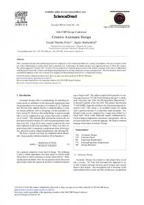
current software design techniques which result in high maintenance cost, limited reusability, extensive need to debug and test, poor documentation, and limited extensionality of the software. ADo-oSS overcomes these shortcomings. One of the final outputs of ADo-oSS is the system architecture, which is represented by the Flow Diagram. The flow diagram can be used in many different applications for a variety of different purposes such as: a. Improvement of the proposed design through identification of coupled designs. b. Diagnosis of the impending failure of a complex system. c. Reduction of the service cost of maintaining machines and systems. d. Engineering change orders. e. Job assignment and management of design tasks. f. Management of distributed and collaborative design tasks. g. Reusability and extensionality of software. In axiomatic design a ‘module’ is defined as the row of design matrix that yields the FR of the row when it is multiplied by the corresponding DP (i.e., data). The AD framework ensures that the modules are correctly defined and located in the right place in the right order. A ‘V model for software’shown in Fig. 1 will be used here to explain the concept of axiomatic design of object-oriented software systems (ADo-oSS). The first step is to design the software following the top-down approach of axiomatic design, build the software hierarchy, and then generate the full design matrix (i.e., design matrix that shows the entire design hierarchy) to define modules. The final step is to build the object-oriented model with a bottom-up approach, following the AD flow chart for the designed system.
Customer Attributes
Coding with System Architecture
Software Product
y ch rar hie ) are ch ftw roa so pp the n A ild ow Bu p-D (To
Bu (B ild th ott om e ob -U jec pA to pp rien roa ted ch ) mod el
Define FRs Establish Interfaces
Mapping Decomposition
Identify classes
Define Modules
Identify Leaves (Full Design Matrix)
Figure 1: Axiomatic Design Process for Object-Oriented Software System (The V model) Axiomatic design of software can be implemented using any software language. However, in the 1990’s most software is written using an object-oriented programming language such as C++ or Java. Therefore, axiomatic design of software is implemented using object-oriented methodology. To understand ADo-oSS, it is necessary to review the definitions of the words used in OOT and their equivalent words in axiomatic design [9]. The fundamental construct for
the object-oriented method is the object1, which is equivalent to FRs. Object-oriented design decomposes a system into objects. Objects ‘encapsulate ‘ both data (equivalent to DPs), and method (equivalent to relationship between FRi and DPi, i.e., module) in a single entity. Object retains certain information on how to perform certain operations, using the input provided by the data and the method imbedded in the object. (In terms of axiomatic design, this is equivalent to saying that an object is [FRi = Aij DPj].) Object-orient design generally uses four definitions to describe its operations: identity, classification, polymorphism and relationship. Identity means that data – equivalent to DPs -- are incorporated into specific objects. Objects are equivalent to an FR -- with a specified [FRi = Aij DPj] relationship-- of axiomatic design, where DPs are data or input and Aij is a method or a relationship. In axiomatic design, the design equation explicitly identifies the relationship between FRs and DPs. Classification means that objects with the same data structure (attributes) and behavior (operations or methods) are grouped into a class. The object is represented as an instance of specific class in programming languages. Therefore, all objects are instances of some classes. A class represents a template for several objects and describes how these objects are structured internally. Objects of the same class have the same definition both for their operations and for their information structure. Sometimes an ‘Object’ is also called a tangible entity that exhibits some well-defined ‘Behavior’. ‘Behavior’is a special case of FR. The relationship between ‘Objects’ and ‘Behavior’may be compared to the decomposition of FRs in the FR hierarchy of axiomatic design. ‘Object’is the ‘parent FR’relative to ‘Behavior’which is the ‘child FR’. That is, the highest FR among the two layers of decomposed FRs is ‘Object’ and the children FRs of the ‘object FR’ are ‘Behavior’. The distinction between ‘Super Class’, ‘Class’, ‘Object’and ‘Behavior’ is necessary in OOT to deal with FRs at successive layers of a system design. In OOT, Class represents an abstraction of Objects and thus, is at the same level as an Object in the FR hierarchy. However, Object is one level higher than Behavior in the FR hierarchy. The use of these key words, while necessary in OOT, adds unnecessary complexity when the results of axiomatic design is to be combined with OOT. Therefore, we will modify the use of these key words in OOT. In ADo-oSS, the definitions used in OOT is slightly modified. We will use one key word ‘Object’to represent all levels of FRs, i.e., Class, Object, and Behavior. ‘Objects with indices’ will be used in place of these three key words. For example, Class or Object may be called Object i, which is equivalent to FRi, Behavior will be denoted as ‘Object ij’to represent the next level FRs, FRij. Conversely, the third level FRs will be denoted as Object ijk. Thus, Object i, Object ij, and Object ijk are equivalent to FRi, FRij, and FRijk, which are FRs at three successive levels of the FR hierarchy. To summarize, the equivalence between the terminology of axiomatic design and those of OOT may be stated as: • An FR can represent an Object. • DP can be data or input for the Object, i.e., FR. 1
Italicized words in this section have specific definitions.
• The product of a module of the design matrix and DP can be a method, i.e., FR = A*DP. • Different levels of FRs are represented as Objects with indices.
paper utilizes the off-diagonal element in the design matrix as well as the diagonal elements at all levels. A design matrix element represents a link or association relationship between different FR branches that have totally different behavior.
The Axiomatic Design of Object-Oriented Software System (ADo-oSS) shown in Figure 1 involves the following steps: a. Define FRs of the Software System The first step in designing a software system is to determine the customer attributes, in the customer domain, which the software system must satisfy. Then, the functional requirements (FRs) of the software in the functional domain and constraints (Cs) are established to satisfy the customer needs.
c.
d.
Definition of Modules – Full Design Matrix One of the most important features for the AD framework is the design matrix, which provides the relationships between the FRs and DPs. In the case of software, the design matrix provides two important bases in creating software. One important basis is that each element in the design matrix can be a method (or operation) in terms of the object-oriented method. The other basis is that each row in the design matrix represents a module to satisfy a specific FR when a given DP is provided. In most cases, the off-diagonal terms in the design matrix are important since most of the coupling comes from these off-diagonal terms. It is important to construct the full design matrix based on the leaf-level FR-DP-Aij to check for consistency of decisions made during decomposition.
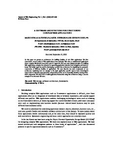
e. Identify objects, attributes, and operations Since all the DPs in the design hierarchy are selected to satisfy FRs, it is relatively easy to identify the objects. The leaf is the lowest level Object in a given decomposition branch, but all leaf-level objects may not be at the same level if they belong to different decomposition branches. Once the Objects are defined, the attributes (or data) – DPs -- and operations (or methods) – products of module times DPs -- for the Object should be defined to construct the object model. This activity should use the full design matrix table. The full design matrix with FRs and DPs can be translated into the OOT structure as shown in Figure 2. f. Establish interfaces by showing the relationships between objects and operations Most efforts are focused on this step in the objectoriented method since the relationship is the key feature. The axiomatic design methodology presented in this
Leaf level FR (Behavior)
Mapping between the Domains and the Independence of Software Functions The next step in axiomatic design is to map these FRs of the functional domain into the physical domain by identifying the design parameters (DPs). DPs are the ‘how's’of the design that satisfy specific FRs. DPs must be chosen to be consistent with the constraints. Decomposition of {FRs}, {DPs}, and {PVs} The FRs, DPs, and PVs must be decomposed until the design can be implemented without further decomposition. These hierarchies of {FRs}, {DPs}, {PVs} and the corresponding matrices represent the system architecture. The decomposition of these vectors cannot be done by remaining in a single domain, but can only be done through zigzagging between domains.
Leaf level DP (DATA Structure) Parent level FR (NAME)
b.
Parent level DP
NAME Design Matrix Elements (METHOD)
(a) Full Design Matrix Table
Mapping
DATA Structure METHOD
(b) Class Diagram
Figure 2: The correspondence between the full design matrix and the OOT diagram The sequence of software development begins at the lowest level, which is defined as the leaves. To achieve the highest-level FRs, which are the final outputs of the software, the development of the system must begin from the inner-most modules shown in the flow chart that represent the lowest-level leaves. Then, move to the next higher level modules (i.e., next innermost box) following the sequence indicated by the system architecture; that is, go from the innermost boxes to the outer most boxes. In short, the software system can be developed in the following sequence: a. Construct the core functions using all diagonal elements of the design matrix. b. Make a module for each leaf FR, following the sequence given in the flow chart that represents the system architecture. c. Combine the modules to generate the software system, following the module junction diagram. When this procedure is followed, the software developer can reduce the coding time since the logical process reduces the software construction into a routine operation. 3
ACCLARO SOFTWARE
In the preceding section, the basic concept for designing software based on Axiomatic Design of Object-Oriented Software Systems (ADo-oSS) was presented. In this section, a case study involving a large, commercial software designed based on ADo-oSS will be presented. The software – called Acclaro – is general-purpose software for designers who practice axiomatic design. The Acclaro software – which means ‘to make clear’ in Latin -- was developed in a relatively short period of time because the ADo-oSS methodology was used. The entire software has many layers of decomposition with more than a thousand of FRs and DPs. Acclaro is an interactive software system for designers of hardware, software, and systems. It is designed to help designers in creating original designs. This software makes
suggestions for design improvements based on the theorems of the design axioms. This computer software automatically generates the ‘Flow Diagram’ of the system architecture when the hierarchies in the FR and DP domains or in the DP and PV domains are established as a result of axiomatic design of systems. The ultimate output of the software is a design that satisfies the functional requirements (FRs) and constraints (Cs). The designer provides inputs to the software such as {FRs}, {DPs}, and {PVs} when prompted by Acclaro software. The designer then answers questions on the relationships between these characteristic vectors, again prompted by the software. Based on these inputs, Acclaro creates design matrices and helps the designer to make correct design decisions. It also prompts the designer when he/she has made a mistake based on various theorems of axiomatic design. The final outcome of the software is the system architecture, which is represented in the form of the {FRs}/{DPs}/{PVs} tree diagram, the module-junction diagram, and the flow diagram. The Acclaro software also generates the final design documentation. It can also be used to manage the software development task. Acclaro software was developed top-down as shown in Table 1 to meet the customer needs given in Table 2. A constraint is that the software must be independent of specific operating systems and run on many computers without change or modification. Therefore, the JAVA language was chosen as the programming language. These top-level FRs and DPs are decomposed until the design task is completed. FR1:
Make the decision-making tool which has impact on the design world DP1: Computerized system with the Axiomatic Design Software Constraints: Independent from the operating system Table 1 Top-level decomposition of Acclaro
CA1 Make design document CA2 User friendly Graphical User Interface CA3 Indicate the user’s mistake or guide CA4 Provide the collaborative design environment CA5 Provide efficient database CA6 Provide decision-making environment CA7 Manage the design activity Table 2 An example of Customer Attributes for Acclaro The desired first level functional software are described in Table 3. Functional Requirements FR1.x Make the decision making P tool which has impact on the design world 1 Manage design workflow Provide decision-making 2 environment Support ease of use while 3 using software 4 Provide efficient data I/O 5 Provide utility function
requirements of the Design Parameters DP1.x Computerized system with the Axiomatic Design Software Design Roadmap Decision making criterion Graphical User Interface (GUI) Data manager Plug in software
Table 3 First-level decomposition of Acclaro
Equation (3) shows the first-level design equation. It is a decoupled design. The design matrix shows that the graphical user interface is the most complex module in the first level because it is affected by all DPs.
FR11 X FR12 X FR14 = X 0 FR15 FR13 X
0 X X 0 X
0 0 X X X
0 0 0 X X
0 DP11 0 DP12 0 DP14 0 DP15 X DP13
(3)
FR2 (Provide decision-making environment) may be decomposed into a sub level with DP2 (Decision making criterion). Table 4 shows the second level decomposition for FR2 and Eq. (4) shows the relationships in the second level for FR2. Functional Design Parameters Requirements DP1.2.x FR1.2.x Provide decisionP Decision making criterion making environment Provide design 1 sequence in terms of Decomposition roadmap Axiomatic Design Maintain functional Criterion for Independence 2 independence Axiom Make suggestions for Criterion for Information Axiom 3 better design and Robust Design Table 4 Second level decomposition for the FR 1.2
FR121 X FR122 = 0 FR123 0
0 X X
0 DP121 0 DP122 X DP123
(4)
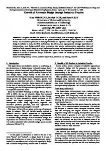
In this manner, the software system can be designed using the AD framework. The Acclaro software design has nine level hierarchies and well over 1000 leaves, which may increase as other features are added. Figure 3 illustrates the full design matrix table with module information for FR1141 branch, which deals with the data structure for FRs, DPs, and design matrices in Acclaro software. The off-diagonal term reveals the interrelationship between FRs and DPs located in different branches. It will guide the integration sequence between objects or classes that will be defined later. The representation of the design for the FR1141 branch based on the FRs and DPs hierarchies and the design matrix can be transformed into the OOT representation as shown in Figure 4. The representation is done using indices for objects in a manner consistent with the indices for FRs and DPs, and also treating the object as consisting of a diagonal element identified by ‘d’after each indices and an off-diagonal element denoted by ‘*’after indices. Using this system, the software designer can generate an object-orient model such as that shown in Figure 4, which is derived from Figure 3. The system architecture for the FR1141 branch may be illustrated as Fig. 5. After the diagonal element in the full design matrix is coded, this flow diagram guides the coding sequence as well as maintenance sequences.
Attributes a
Attributes b
2
4
AttribuAttributes e tes d
Attributes c DP1141
1 2
3
6
1 2 3 1 2 3
4
1
2
1 2 3 1 2
3
1
3 2
1 2
1 2 3 4
1 2 3 4
1
2
3 4
1 2
1
Object D
Object C
FR1141
Object B
Object A
1 2 3 4
Object E
3
Column check Row check New method Attributes for GUI Attributes for system architecture Rearrange method New method Attributes for rearranged design matrix Status check method Copy method Column change method Row change method Exchange method On/Off changing method New method Attribute for GUI Attribute for design matrix Delete method Change method New method Drag & Drop method Paste method Cut method Copy method Attribute for GUI Pointer to the child level Attribute for DP Delete method Change method New method Drag & Drop method Paste method Cut method Copy method Attribute for GUI Attribute for FR
4
4
1 Describe the FRs X 2 Deisplay to the graphics 1 Support copying X 2 Support cutting X 4 3 Support pasting X 2 4 Support moving X 3 1 Make a new storage X 2 Support changing X 3 Support deleting X 1 Describe the DPs 2 Connect the child level 3 Display to the graphics 1 Support copying X 2 Support cutting X 4 4 3 Support pasting X 4 Support moving X 4 1 Make a new storage 2 Support changing 3 Support deleting X 1 Define the design matrix X 2 Display to the graphics 1 Make a new storage X 1 Change each element 1 2 Change between def. DP and Alt. DP 2 3 Change row element 3 4 Change column element 3 Support copying X 4 Check the status of design matrix 6 1 Define the rearranged design matrix X 2 1 Make a new storage 2 2 Support matrix rearrange 1 Define the system architecture X 2 Display to the graphics 3 1 Make a new storage X 3 1 Find parallel flow 2 2 Find serial flow
X X X X X X X X
Fd
X
X X X X X X X X
X X X X X
X X X X X X X X
Gd
X X X X X X
X X X X
X X X X
X X X X
G*
X X X X X X X X X X X X X X
X X X X X X X
X X X X X X X X
X X X X X X X X X
X X X X X
X X X X X X X X X X X
H*
Hd
X X X X
X
X X X X X
X X
X X
X
I*
X X
X X
X X X
X
J*
X
X X X X
2 1 2
Module Infomation M114121 M114122 M11412341 M11412342 M11412343 M11412344 M1141231 M1141232 M1141233 M114141 M114142 M114143 M11414441 M11414442 M11414443 M11414444 M1141441 M1141442 M1141443 M1141611 M1141612 M11416131 M114161321 M114161322 M114161323 M114161324 Id M11416133 M11416134 M1141621 X M11416221 X M11416222 X Jd M1141631 X M1141632 X X X M11416331 X X X M114163321 X X X X M114163322
Figure 3 Full design matrix table for FR1141 branch
Class FR11412 & FR11414
Class FR11416
Class B
Class A a
Class D
Class C
Class E
Fd Class Bd b
Class B* a
Gd
G*
Class Cd
Class C*
c Hd
a, b H*
Class Dd d
Class D* a, b
Class Ed e
Class E* a, b, c, d
Id
I*
Jd
J*
Figure 4 Object-oriented model generation
M11412 M114121
M114123 M1141234
M1141231
M11412341 M114122
M1141232
M11412342
M1141233
M11412344 M11412343
M11414 M114141 M114142 M114143
M114144 M1141444
M1141441
M11414441
M1141442
M11414442 M11414444
M1141443
M11414443
M11416 M114161
M1141613 M11416132 M11416131 M114161321
M1141611 M1141612
M114161322 M114161323 M114161324 M11416133 M11416134
M114162 M1141621
M1141622 M11416221 M11416222
M114163 M1141631 M1141632
Summation Junction
M1141633 M11416331 M11416332 M114163321
M114163322
Control Junction
Figure 5 Flow diagram at the fourth level decomposition for Acclaro software. 4 CONCLUSION Software development can be done efficiently in a shortest possible time, reliably with full confidence when it is done based on axiomatic design. The use of axiomatic design also provides many other benefits such as distributed system design, rational management of the development process, ease of engineering change orders, tracing of malfunctions during service and maintenance, and others. It certainly leads to short lead-time, reliability, low development cost and high productivity. Acclaro software system has been developed to help designers to develop rational and correct designs from the beginning without resorting to prototypes and debugging. This software was designed quickly as a result of axiomatic design. 5 REFERENCES [1] R.S. Pressman, Software Engineering, 1997, A Practitioner’s Approach, 4th ed., McGraw Hill, New York. [2] Kim, S.J., N.P. Suh, and S.-K. Kim, 1991, Design of software systems based on axiomatic design, Annals of the CIRP, Vol. 40, No. 1 [also Robotics & ComputerIntegrated Manufacturing, 3:149-162, 1992].
[3] Suh, N.P., 1997(a), Design of Systems, Annals of CIRP, Vol. 46, No. 1. [4] S.H. Do and G.J. Park, 1996, Application of Design Axioms for Glass-Bulb Design and Software Development for Design Automation, 3rd CIRP Workshop on Design and Implementation of Intelligent Manufacturing, pp. 119-126, June 19-22, Tokyo, Japan. [5] Suh, N.P., 1990, The Principles of Design, Oxford University Press., New York. [6] Suh, N.P., 2000, Axiomatic Design: Advances and Applications, Oxford University Press, New York (to be published). [7] Suh, N.P., 1995(b), Design and Operation of Large Systems, Journal of Manufacturing Systems, Vol. 14, No.3, pp. 203-213 [8] Suh, N.P., Cochran, D. S., and Lima, P.C., 1998, Manufacturing System Design, CIRP Annals, Volume 47, No. 2. [9] J. Rumbaugh, M. Blaha, W. Premerlani, F. Eddy, and W. Lorensen, 1991, Object-Oriented Modeling and Design, Prentice Hall, New Jersey.