The Design of Mixed Hardware/Software Systems Jay K. Adams
Donald E. Thomas
Synopsys, Inc. 700 East Middlefield Road Mountain View, CA 94043
[email protected]
Deptartment of Electrical and Computer Engineering Carnegie Mellon University Pittsburgh, PA 15213
[email protected]
Abstract Over the past several years there has been a great deal of interest in the design of mixed hardware/software systems, sometimes referred to as hardware/software co-design or hardware/software co-synthesis. However, although many new design methodologies have taken the name hardware/software co-design, they often do not seem to share much in common with one another. This partly due to the fact that the problem itself has so many dimensions. This tutorial describes a set of criteria that can be used to compare differing approaches to hardware/software co-design. These criteria are used in the discussion of a number of published hardware/software co-design techniques to illustrate how a wide range of approaches can be viewed within a single framework.
1 Introduction Because of the growing complexity of digital systems and the availability of a variety of implementation technologies, many digital systems today are mixed hardware/software systems. The hardware and software elements may be either physically separate components or the same physical components viewed at different levels of abstraction. In either case the interdependency of the hardware and software elements often leads to trade-offs in the way one or the other is implemented. The design of mixed hardware/software systems presents several challenges to the designer. Not the least of these is the fact that even though the hardware and software components are interdependent, they are typically described and designed using different formalisms, languages, and tools. Hardware/software co-design is an attempt to integrate hardware and software design techniques with the goal of incorporating more of the system design process into a single design methodology. Combining hardware and software design tasks into a common methodology or automation tool has several advantages. One is that including more of the system into an automated or structured design
methodology may accelerate the design process. Another is that addressing the design of hardware and software components simultaneously under a single methodology may enable hardware/software trade-offs to be made dynamically, as the design progresses. Approaches to hardware/software co-design are becoming common in the literature. However, the proposed methodologies differ widely and have been slow to converge around a small number of formalisms or techniques. This lack of convergence is due in part to the widely differing assumptions made in each case. The assumptions include what part of the system makes up the hardware and software, what aspects of the design are variable and what parts are fixed, the design goals, and so on. This tutorial attempts to lend some structure to the field of hardware/software co-design by defining terminology and suggesting some criteria that can be used to compare various approaches to co-design. First, Section 2 offers a broad classification of hardware/software systems in terms of the relationship between the hardware and software components, which is similar to that of [1]. Then, Section 3 discusses some of the design tasks can be addressed by hardware/software co-design. Section 4 illustrates these principles as they apply to a variety of published examples of hardware/software co-design.
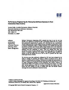
2 Mixed hardware/software systems For the purposes of our discussion, a mixed hardware/software system is any digital system that includes both hardware and software components designed using a single methodology. Many digital systems contain both hardware and software, but unless the two are designed together, we do not think of it as a mixed hardware/software system. When we speak of the hardware and software components of the system, we are referring to just those components that are part of a particular design methodology. Two broad classifications can be used to distinguish different types of hardware/software systems. The distinguishing factor is whether the boundary between hardware and software is logical boundary (Type I) or a physical boundary (Type II). Figure 1 illustrates the difference between Type I and Type II hardware/software systems. In a Type I hardware/software system the hardware is thought to be executing the software. The the relationship between the two is one of abstraction level. Such a system may contain one or more physical components. An example of a Type I hardware/software system is one made up of a microprocessor and its associated glue logic. In this case the hardware, which is probably specified as a microprocessor type and a netlist of gates, is viewed at a much
33rd Design Automation Conference Permission to make digital/hard copy of all or part of this work forpersonal or class-room use is granted without fee provided that copiesare not made or distributed for profit or commercial advantage, thecopyright notice, the title of the publication and its date appear,and notice is given that copying is by permission of ACM, Inc. Tocopy otherwise, to republish, to post on servers or to redistribute tolists, requires prior specific permssion and/or a fee. DAC 96 - 06/96 Las Vegas, NV, USA 1996 ACM, Inc. 0-89791-833-9/96/0006..$3.50
process 1
process 2
...
process n software hardware
component 1 component 2
. . . component n
hardware-software partitioning
hardware-software co-simulation
hardware-software co-synthesis hardware-software co-design
(a) Type I HW/SW Systems
system design process 1
process k
process k+1
process n Figure 2: HW/SW system design activities.
...
...
software component 1 component k
component k+1 component n
software hardware
application software
hardware send, receive, wait
application specific hardware
operating system
(b) Type II HW/SW Systems device driver
register reads/writes interrupts
bus interface
Figure 1: Types of mixed HW/SW systems. system bus lower level of abstraction than the software, which is likely to be specified using a high-level programming language. In a Type II hardware/software system, the hardware and software components are modeled at the same level of abstraction and are physically separate components. An example of a Type II hardware/software system is one comprising both a microprocessor and a special-purpose computing engine. If the special-purpose engine is designed using behavioral synthesis techniques, then the hardware, which is specified by a behavioral description, can be modeled at roughly the same level of abstraction as the software. Hardware/software co-design can be attempted for both types of hardware/software systems. In Type I systems, the hardware and software configurations may be interdependent, leading to tradeoffs in the way the two are organized. In some cases, the boundary between hardware and software may be movable, leading to tradeoffs in whether hardware or software is used to implement some of the functionality. In Type II systems, the hardware and software components may also be inter-dependent. Furthermore, there may be an opportunity to choose whether to use one of the software components or one of the hardware components to implement some of the functionality, leading to a greater set of hardware/software trade-offs. Also in Type II systems, the interaction between hardware and software components can be modeled at a variety of abstraction levels. Finally, it is conceivable that a hardware/software system could represent a mixture of Type I and Type II hardware/software boundaries, but to our knowledge, no published work has addressed this situation.
3 System design tasks Approaches to hardware/software co-design can be characterized by the design activities for which hardware and software are integrated. Figure 2 summarizes how the various system design tasks
bus transactions
system bus
Figure 3: HW/SW interface abstractions. are related. Examples of system design methodologies can be found that fit into every subset of this diagram.
3.1 Hardware/software co-simulation Simulation of hardware/software systems, sometimes called hardware-software co-simulation, presents the problem of modeling the behavior of a system based on the behavior of the hardware and software components. The problem is that these components may have differing semantic models and be described using different languages. The purpose of co-simulation may be to flesh out the functionality of hardware and software early in the design process or to integrate the two late in the design process. It may be aimed at verifying the functionality of the system [2] [3] or at evaluating the performance [4] [5]. Hardware/software co-simulation requires a simulation environment that can understand the semantics of both the software and the hardware components and how actions in one domain affect the state of the other. The interaction of the hardware and software may be modeled at a variety of abstraction levels. Figure 3 illustrates some of the abstraction levels at which hardware and software interaction might be modeled for a Type II hardware/software system. At the lowest level, the interface between the hardware and the software may be modeled by the activity on the pins of a CPU or the wires of a bus [4]. This approach is most accurate for evaluating performance, but is computationally expensive. If the hardware and software elements of the system communicate asynchronously, the interaction could be modeled at a high level by the process or device communication mechanism provided by an operating system [2] [3]. This approach is much very efficient computationally, but may not be useful for evaluating performance.
3.2 Hardware/software co-synthesis Co-design may also include integrated synthesis of hardware and software components, which we refer to as hardware/software cosynthesis [6] [7] [8] [9] [10]. Automated hardware/software co-synthesis may allow the designer to explore more of the design space by dynamically reconfiguring the hardware and software to find the best overall organization as the design evolves. This can lead to better results than could be achieved if the hardware and software architectures had to be specified up-front, during the early stages of the design. Design tools for hardware/software co-synthesis must understand the relationship between the hardware and software organizations and how design decisions in one domain affect the options available in the other. It also requires an understanding of how the overall system cost and performance are affected by the hardware and software organizations. Another challenge for hardware/software co-synthesis is that hardware and software are often described using different languages and formalisms. If a design methodology considers moving functionality back and forth between hardware and software, a unified understanding of hardware and software functionality must be reached.
3.3 Hardware/software partitioning Hardware/software co-synthesis may include hardware/software partitioning. This is the case whenever the design methodology allows for a choice between using hardware and software to implement some of the functionality. Attempts at hardware/software partitioning can be characterized by the factors that influence the partition. The set of factors used in any particular situation is closely tied to the design goals. Many factors may influence the hardware/software partitioning problem. Some of the considerations that can be taken into account are as follows: Performance requirements. Functions that have a great impact on the overall performance of the system may need to be implemented in hardware. This may be the case even if a hardware implementation of the function offers only a modest improvement in performance. Implementation cost. Finding an effective hardware/software partition may involve considering the cost of producing a hardware implementation of some of the functionality. If hardware resources can be shared among functions, it may also be necessary to consider how the partition impacts the sharing. Modifiability. Sometimes a software implementation is desired so that the function or algorithm can be easily changed. Nature of computation. The function in question may have an affinity for either hardware or software. Computations which benefit from a high degree of data parallelism, for instance, may be better suited for hardware. For Type II hardware/software systems, hardware/software partitioning implies physical partitioning. In this case the partitioning problem is further complicated by the following issues: Concurrency. If the software and hardware components run asynchronously, the best system performance may be achieved by exploiting concurrency among them. Communication. The overhead of synchronization and data transfer among the hardware and software components is likely to have a significant impact on overall performance. This fact favors partitions that localize communication, even at the expense of other considerations.
application code I/O drivers software
microprocessor
hardware interface hardware and glue logic Figure 4: An embedded microprocessor system.
4 Examples of hardware/software co-design Several examples of hardware/software co-design have been published over the past several years. This section illustrates how the criteria presented in the previous two sections can be used to characterize and compare various approaches to hardware/software co-design.
4.1 Embedded microprocessor systems One instance of hardware/software co-design involves the design of a system consisting of an embedded microprocessor and some associated interface or glue logic. In this case the software running on the dedicated microprocessor may have to interact with the surrounding hardware in some way. An embedded microprocessor design problem is illustrated in Figure 4. In this configuration of hardware and software, the hardware is modeled and designed at a much lower level of abstraction than the software. For this reason, we consider this to be an example of a Type I hardware/software system. The co-simulation technique described in [4] simulates the software running on the microprocessor in conjunction with the surrounding hardware using a Verilog simulator. This approach is an example of hardware/software co-simulation using existing hardware simulators and software compilers. The interaction between the hardware and software is modeled at the level of activity on the pins of the CPU. The Chinook system [11] performs hardware/software co-synthesis of the software I/O drivers and hardware interface logic. The Chinook system uses a common specification for the hardware and software components, but does no hardware/software partitioning. Instead, Chinook concentrates on co-simulation and interface synthesis.
4.2 Heterogeneous multiprocessing systems Another instance of hardware/software co-design is the design of a distributed, heterogeneous embedded processor. Figure 5 shows a diagram of a such a system. We consider this to be a Type I hardware/software system. Since the boundary between the hardware and software is again one of abstraction level. The design involves both choosing the number and type of processing elements and mapping software tasks onto processing elements. The goal is to meet some performance objective while minimizing the cost of the hardware, either by choosing inexpensive
appl. code
appl. code
...
appl. code
software
native code storage
hard-wired controller
data path
hardware µ proc. type 1
µ proc. . . . µ proc. type 2 type n
software hardware Figure 6: An application-specific instruction set processor.
interconnection network Figure 5: A heterogeneous, distributed multi-processing system. processing elements, reducing the number of processing elements, or both. Several approaches to the design of heterogeneous multiprocessing systems have been published recently [9] [12] [13]. The key difference in the approaches is the way the processing elements are specified and the way the optimization is performed. In [12] the processing elements are chosen from a library of available microprocessors, each characterized in terms of processing speed and cost. Optimizing the system takes the form of selecting the set of processing elements and mapping the tasks onto the processors. The optimization is done using integer linear programming, which yields the optimum configuration and mapping. In [13] the processing elements are specified abstractly by their processing capacity. Optimization, which also involves choosing the number and type of processing elements and mapping the tasks onto them, is done using a vector bin packing approach. All of these approaches to automated design of heterogeneous multiprocessing systems offer a similar set of hardware/software trade-offs. A more highly parallel software architecture allows the use of slower, less-expensive processing elements. On the other hand, less parallelism in the software architecture allows fewer processing elements to be used, also lowering the cost. The goal is to find the right balance between the two extremes minimizing the cost of the system while meeting the performance goals. Because the design methodology does not include the possibility of choosing between hardware and software implementations for some part of the system, we think of it as an instance of hardware/software co-synthesis but not of hardware/software partitioning.
4.3 Application-specific instruction set processors Another published example of hardware/software co-design is the design of an application-specific instruction set processor [14]. As shown in Figure 6, the hardware/software boundary in this case lies between the software running on the processor and the processor itself. Hardware/software co-design for an application-specific instruction set processor attempts to find the best hardware implementation for a given software application or set of applications. Generally this involves coming to an understanding of how the structure of the hardware implementation impacts the performance of the software. In some cases, the design of an application-specific instruction set processor affords the opportunity to move the boundary between hardware and software by, for instance, adding new instructions to the instruction set architecture. In these cases, hardware/software
native code storage
hard-wired controller
software
data path
hardware
Figure 7: An instruction set processor with special-purpose functional units. co-design for an instruction set processor can include hardware/software partitioning. Modifiability is likely to be an important factor in finding the best hardware/software partition in such cases. Note that the diagram shown in Figure 6 would also apply to the design of a general-purpose instruction set processor, but in that case, the application software is usually not part of the design methodology and is not known ahead of time. For this reason, we generally do not consider general-purpose processors to be examples of mixed hardware/software systems.
4.4 Special-purpose functional units A slightly less general example of reconfiguring an instruction set processor for a given application is that of adding special-purpose functional units to the processor data path. Figure 7 illustrates the hardware and software components of such a system. Like the previous example, we consider this to be Type I hardware/software system. Hardware/software co-design for this type of system has been proposed in [15]. Like application-specific instruction set processors, specialpurpose functional unit systems offer an opportunity for hardware/software partitioning. The partitioning is limited by the need to incorporate the hardware into an existing data path and controller. However, what makes this configuration interesting is the possibility of using field programmable hardware to implement the specialpurpose functional units. In this case, the hardware/software partition need not be static and could be adapted on the fly to suit a wide variety of circumstances.
4.5 Application-specific co-processors In some cases, the performance of an instruction set processor can be augmented by adding one or more application-specific or custom co-processors. The purpose of the custom co-processor is to off-load some of the more computationally intensive tasks from the main instruction set processor, which may be either a
native code storage
microprocessor
native code storage
microprocessor
software
co-processor interface logic controller
data path
software
hardware
ctrl
data path
ctrl
data path
Figure 8: An instruction set processor with a custom co-processor. hardware general purpose or special purpose (e.g. DSP) processor. The software component of such a system is the code that is to run on the instruction set processor, while the hardware component is the custom co-processor. Figure 8 shows a diagram of a custom co-processing system with the hardware and software boundaries outlined. We consider this type of system to be a Type II hardware/software system, since the hardware component includes its own data path and controller and can be specified and modeled at the same level of abstraction as the software. The hardware/software trade-off in the design of custom coprocessors is between implementing some function using the instruction set processor or implementing it using the custom coprocessor. Since the design methodology allows a choice between hardware and software, we consider this to be an example of both hardware/software co-synthesis and hardware/software partitioning. Custom co-processor systems afford many degrees of freedom to the designer, because the structure of the co-processor is largely separate and independent of that of the instruction set processor. A custom co-processor might, for example, be organized as specialpurpose scalar (SISD) processor, a long instruction word (SIMD) machine, or even a multi-threaded (MIMD) processor with a number of controller/data path pairs. Several design methodologies dealing with application-specific co-processor systems have been introduced [6] [16] [17]. While they are similar in their view of the hardware and software components, they differ in the considerations taken into account during hardware/software partitioning. In [17] the custom co-processor is defined to be a SIMD machine and the behavioral specification limited to a single thread of control (specifically, a software program). Hardware/software partitioning is aimed at moving the performance-critical regions of code into hardware. Performance requirements and hardware implementation cost are the principle factors considered in the partitioning. The approach taken in [6] is to design the co-processor using high-level synthesis techniques using the instruction set processor to perform non-critical computations. The goal of hardware/software partitioning in this case is to minimize the hardware implementation cost without decreasing performance relative to a purely hardware implementation. Performance requirements are have the most impact on the hardware/software partition in this case. In [16] hardware/software partitioning is performed with an eye toward performance requirements, implementation cost, and, to some extent, concurrency. Furthermore, the implementation cost formulation [18] considers the potential for sharing resources among the set of functions implemented in hardware, which further complicates the partitioning problem.
Figure 9: A multi-threaded custom co-processor.
4.5.1 Multi-threaded co-processors A slight generalization of the custom co-processor arrangement is one in which the custom co-processor is understood to comprise more than one controller and data path and, consequently, is able to implement concurrent threads of control. Figure 9 shows the hardware/software boundary for multi-threaded co-processor systems. In this case the hardware/software partitioning problem is further complicated by the opportunity to exploit parallelism both between hardware and software components and among hardware components. In [10] hardware/software partitioning is done in a way that considers minimizing the communication between the hardware and software components and maximizing the concurrency between them and within the multi-threaded co-processor. The hardware/software partitioning approach considers all the factors outlined in Section 3.3 except for modifiability. A technique for applying hardware/software co-simulation to this type of system was presented in [3]. The approach suggested was to model the interaction between the hardware and software components at a high level using “send,” “receive,” and “wait” operations. In this case the purpose of performing co-simulation was to verify the functionality of the hardware and software components working together.
5 Summary In this tutorial we have presented a set of criteria that can be used to compare approaches to hardware/software co-design. Briefly stated, these criteria are as follows: 1. The type of hardware/software system is being designed (e.g. Type I, Type II). 2. The system design tasks are being addressed (e.g. co-simulation, co-synthesis, hardware/software partitioning). 3. If co-simulation is addressed, the level of abstraction at which the hardware/software interaction is modeled (e.g. signal activity, communicating processes). 4. If hardware/software partitioning is addressed, the considerations that are taken into account (e.g. performance requirements, implementation cost, modifiability, nature of computation, concurrency, communication).
We illustrated how to apply these criteria to some examples of hardware/software co-design representing a wide range of system types and design goals. Since hardware/software co-design can mean many things, it is important to determine characteristics of a given approach before evaluating it or comparing it to some other example.
[8] D. D. Gajski, F. Vahid, S. Narayan, and J. Gong, Specification and Design of Embedded Systems. Englewood Cliffs, NJ: Prentice Hall, 1994. [9] T.-Y. Yen and W. Wolf, “Sensitivity-Driven Co-Synthesis of Distributed Embedded Systems,” in Proc. 8th Int. Symposium on System Synthesis, 1995.
Acknowledgment
[10] J. K. Adams and D. E. Thomas, “Multiple-Process Behavioral Synthesis for Mixed Hardware-Software Systems,” in Proc. 8th Int. Symposium on System Synthesis, 1995.
This work is supported by the Semiconductor Research Corporation under contract #DC-95-068.
[11] P. H. Chou, R. B. Ortega, and G. Borriello, “The Chinook Hardware/Software Co-Synthesis System,” in Proc. 8th Int. Symposium on System Synthesis, 1995.
REFERENCES
[12] S. Prakash and A. C. Parker, “SOS: synthesis of application-specific heterogeneous multiprocessor systems,” Journal of Parallel and Distributed Computing, vol. 16, no. 4, pp. 38–51, 1992.
[1] A. Kalavade and E. A. Lee, “Manifestations of Heterogeneity in Hardware/Software Codesign,” in Proc. 31th DAC, 1994. [2] D. E. Thomas, J. K. Adams, and H. Schmit, “A Model and Methodology for Hardware/Software Codesign,” IEEE Design & Test of Computers, vol. 10, no. 3, pp. 6–15, 1993. [3] S. L. Coumeri and D. E. Thomas, “A Simulation Environment for Hardware-Software Codesign,” in Proc. ICCD ’95, 1995.
[13] J. Beck, Autoamted Processor Specification and Task Allocation Methods for Embedded Multicomputer Systems. PhD thesis, Carnegie Mellon University, April 1995. [14] J. Soto, A. Y. Alomary, Y. Honma, T. Nakata, A. S. adn N. Hikichi, and M. Imai, “PEAS-I: A Hardware/Software Codesign System for ASIP Development,” IEICE Trans. Fundam. Electron. Commun. Comput. Sci., vol. E77-A, pp. 483–91, March 1994.
[4] D. Becker, R. K. Singh, and S. G. Tell, “An Engineering Environment for Hardware/Software Co-Simulation,” in Proc. 29th DAC, 1992.
[15] P. M. Athanas and H. F. Silverman, “Processor Reconfiguration Through Instruction-Set Metamorphosis,” Computer, vol. 26, no. 3, pp. 11–18, 1993.
[5] A. Kalavade and E. A. Lee, “A Hardware/Software Codesign Methodology for DSP Applications,” IEEE Design & Test of Computers, vol. 10, no. 3, pp. 16–28, 1993.
[16] D. D. Gajski, F. Vahid, and S. Narayan, “A system-design methodology: executable-specification refinement,” in Proceedings of European Design and Test Conference, 1994.
[6] R. K. Gupta and G. De Micheli, “Hardware-Software Cosynthesis for Digital Systems,” IEEE Design & Test of Computers, vol. 10, no. 3, pp. 29–41, 1993.
[17] J. Henkel, R. Ernst, U. Holtmann, and T. Benner, “Adaptation of partitioning and high-level synthesis in hardware/software co-synthesis,” in Proc. ICCAD, 1994.
[7] R. Ernst, J. Henkel, and T. Benner, “Hardware-Software Cosynthesis for Microcontrollers,” IEEE Design & Test of Computers, vol. 10, no. 4, pp. 64–75, 1993.
[18] F. Vahid and D. D. Gajski, “Incremental Hardware Estimation During Hardware/Software Functional Partitioning,” IEEE Transactions on VLSI Systems, vol. 3, no. 3, 1995.