Nagano, K., Katsura, T., Takeda, S., Saeki, E., Nakamura, Y., Okamoto, A. & Narita, S. (2005). Thermal characteristics of steel foundation piles as ground heat ...
FEASIBILITY STUDY OF SNOW MELTING SYSTEM USING GROUND THERMAL ENERGY IN JAPAN K. Nagano, Y. Hiraga, T. Katsura, T. Nogawa, S. Takeda and S. Nakabayashi Graduate School of Engineering, Hokkaido University Sapporo, 060-8628 JAPAN Tel: 81-11-706-6285 nagano @eng.hokudai.ac.jp 1.
BACKGROUND
A half of the Japanese land has been legislated as the heavy snowfall area by the government and more than twenty million people live there. Snow precipitation in a day sometimes reaches over 600 mm high and people expend a considerable amount of work and time remove accumulated snow and to maintain the daily activities. The top of citizen’s demands to solve municipal issues is always related snow in this area. In order to enhance urban appeal as well as the safety and comfort daily life, the snow melting system of the pavement has been getting more recognition in the central are of the city. Popular snow melting systems use electrically heating wire buried in the pavement. On the other hand, hot water piping systems heated by kerosene or gas boilers are also commonly used for not only residential front yards but also for big parking spaces and precipitous roads. However, snow melting systems consume much bigger amount of thermal energy than most people think due to a large amount of heat loss to the ambient in addition to needed heat for melting snow. For example, 400 litters of oil are burned in winter season for 20 m2 wide residential snow melting system in average in Hokkaido area. This amount of oil consumption is almost equivalent to the annual oil consumption for domestic hot water supply of a single family house. From energy conversation and CO2 reduction as well as saving running expense point of view, heat pump technologies have been applied into the snow melting system in the northern districts of Japan. Some kinds of natural heat resources such as air, ground water and ground heat source become the candidates of the heat source of the heat pump. In particular, ground heat source has been recognized as the most promising potential on account of its universal existence and long term indubitability. In fact, more than 25 big snow melting systems which have ground heat source heat pump systems (GSHP) as the heating units have been installed by the end of 2004 primarily in the northern part of Honshu Island. A simple method according to the steady state or numerical calculations using FDM by scientists has been carried out in the case of planning and designing. However, there has been no reasonable designing and performance prediction tool which bases on the theoretical calculation and provides user friendly interfaces and graphical data output screens for the GSHP snow melting system (GSHP-SM). The authors have developed a novel designing and performance prediction tool for the GSHP snow melting system. This tool has following very strong advantages. 1. High speed heat transfer calculating algorithm for multiple wells based on hourly heat demand 2. Providing user friendly data input interfaces and graphical output screens 3. Plural combinations of on-off control for snow melting system 4. Direct circulation mode between ground and pavement is also available 5. Physical properties of general soils and materials are included 6. Inverter-control heat pump unit can be applied In this paper, the outline of the developed novel designing and performance prediction tool is explained first. Next, a new type heat pump with an inverter-control compressor and measurement of its performance are explained. Last, possibility region for direct circulating for snow melting system is discussed by using developed designing tool and the effect of grid spacing of GSHP-SM with heat recharge applied collected solar energy through embedded piping in the pavement during summer is also discussed. 2.
A DEVELOPED DESIGNING AND PERFORMANCE PREDICTION TOOL FOR GSHP-SM
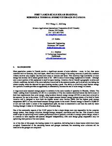
Configuration of GSHP-SM is shown in Figure 1. It can be divided into mainly three parts. First part is snow melting pavement. Second is a heat pump unit as heating unit. Third is ground heat exchangers and surrounding ground. According to these three parts, the authors develop numerical calculation modules.
Snowfall or rainfall Solar radiation Long wave radiation
Snow melting pavement
Heat pump calculation module
Evaporation
Heat convection
Heat pump unit
Snow melting pavement heat transfer calculation module
Heat conduction
piping Adiabatic condition
Adiabatic condition
Hot water circulating piping
Ground Borehole heat exc hanger (BHEX)
Ground heat transfer calculation module
T= Tso (constant)
Figure 1: Configuration of ground heat sour heat pump snow melting system - calculation modules and heat transfers on the surface of the pavement. Boundary condition on the pavement
Air temp. < 2 o C
N
N Snowfall
Remained snow Y
Y
Wet snow
Surface temp. > 0 o C
Dry or wet snow
N Rainfall Dry snow Y Surface temp. > 0 o C
Part8
Part1
Part2
Part3
Part4
Part5
Part6
Tentative snow surface temp > 0 o C
Part7
Figure 2: Flow diagram of boundary conditions on the surface of the pavement. Heat transfer of snow melting pavement In order to calculate transient heat conductive phenomena in the pavement, the implicit finite deferential method is used as illustrated in Figure 1. According to the vertical adiabatic condition based on the average fluid temperature in piping, the calculating region provides a half of inner piping spacing. Appropriate physical properties are given for the plural horizontal layers. On the other side, the heat balance equation on the surface reflects the actual heat transfer phenomenon, which includes convective and radiative heat transfers between the ambient, heat for phase change of the snow and water, heat conduction through the accumulate snow layer, evaporation of liquid water and heat flux from the inner pavement side. Here, we assume that melted snow is once absorbed in the accumulated snow up to 15 % of volumetric water contents and then drains. Finally, the authors summarized these boundary conditions into eight cases according to the surface condition of the pavement as indicated in Figure 2.
Calculation of heat output from a heat pump unit This tool has provided approximate performance functions of actual heat pump units according to the fluid temperatures of primary- and secondary-side made from presented performance curves. On the other side recent emerged inverter-control heat pump units have possibility to modify seasonal coefficient of performance (COP) as well as to stabilize the output temperature of secondary-side. This will give great advantages to GSHP-MS. Here, the authors actually measure a newly developed high performance heat pump unit which has a 10 HP scroll type compressor driven by an inverter unit with a liquid-gas heat exchanger. A photograph in Figure 3 shows a used testing apparatus for a middle class of a heat pump unit up to 30 HP. The feature of this testing apparatus is that it works almost autonomously by applying a plate type heat exchanger between primary-side and secondary-side. In other word, extracted heat is supplied from thermal output and surplus heat is released by a convector or cooled by water. Measured results are shown in Figure 4. It is very important that COPs become incredible high at the partload operation under 35 oC of secondary-side outlet temperature T2out. This characteristic is very effective for GSHPSM which has a wide fluctuation range of the heat demand and a seasonal long term operation. From these experimental results COP of this heat pump unit can be numerically expressed by using following three parameters, which are heat output Q2, primary-side inlet temperature T1in and secondary-side outlet temperature T2out. COP = −0.0557 Q 2 + 0.0985T1in − 0.095T2 out + 8.63
(1)
In the real calculation in the tool, required T2out is determined, then T2in is resulted after the heat transfer from piping to surrounding pavement and Q2 is calculated from the temperature difference between T2out and T2in. Finally, COP of the heat pump unit and needed rotation frequency of the compressor under this condition is determined.
Figure 3: Photograph of Heat pump performance testing apparatus. T 2out = 25 o C
8.0
T 2out = 45 o C
6.0
1740rpm
1740rpm
2320rpm
7.0
5.0
4.0
10
20
30 Q2[kW]
40
50
0 oC -5 o C 3190rpm T1in = -10 o C
2.0
3.0
2900rpm 5 oC
3.0
-5 o C T1in = -10 o C
2320rpm 15 o C
10 o C
COP[-]
4.0
2900rpm 3190rpm 3480rpm 15o C 3.0 5o C 10o C 0o C -5 o C T 1in = -10 o C
5.0
1740rpm
2900rpm 4.0 15o C 10 o C 3190rpm 5 oC 3480rpm 0 oC
2320rpm
6.0
COP[-]
COP[-]
T2 out = 35 o C
5.0
2.0 10
20
30 Q 2[kW]
40
50
10
20
30 Q2[kW]
Figure 4: Performance diagram of Heat pump measured by using a testing apparatus.
40
Modeling of ground heat exchanger and calculation of heat transfer in surrounding ground Heat capacity of the fluid in the ground heat exchanger is taken into account as the one mass system and heat balance according to the temperature deference between fluid and borehole surface is calculated. On the other hand, superposition of temperature responses of the cylindrical heat source theory is adapted to the calculations of heat transfer in the ground surrounding ground heat exchangers. Also, the authors have invented a unique computational technique for very high speed calculation of heat interaction among multiple ground heat exchangers. More detail information is referred to the published papers. 3.
DISCUSSION OF RESULTS
Performance predictions of snow melting system by using ground thermal energy Performance of snow melting system by using ground thermal energy is predicted in six cities in the snowy region of Japan shown in Figure 5. Table 1 indicates representative ground temperatures and the maximum snowfall rates for six selected cities, which are Sapporo, Aomori, Akita, Yamagata, Toukamachi and Toyama. Here, the authors examined two systems. One is examination of available region of the direct circulating system, which means direct use of ground thermal energy for snow melting by circulating fluid between ground heat exchangers and piping in pavement without a heat pump unit. The other one is examination of variation of performance due to grid spacing of ground heat exchangers of GSHP-SM.
15 13 11 9 7 5
[ºC]
Hokkaido Sapporo
Akita
Aomori
Toukamachi Yamagata Toyama Honsyu
Kyusyu Shikoku
Okinawa
Figure 5: Locations of selected six cities in Japan and the annual average air temperature.
Table 1: Uses ground temperature and maximum snowfall rate of selected six cities. Name of city
Sapporo
Aomori
Akita
Ground temperature [oC]
10.4
11.8
12.9
Maximum snowfall rate [cm/h]
2.08
2.43
Needed heat output [W/m2]
198
227
Yamagata
Toukamachi
Toyama
12.8
12.9
15.1
1.77
1.11
7.41
4.34
165
104
690
412
Examination of available region for the direct circulating system The direct circulating system with grid geometry consisted from twenty five 50-meters long borehole type heat exchangers (BHEX) is examined for snow melting area of 300 m2 in these six cities as shown in Figure 6. Total length of BHEX reaches 1500 m. As the seasonal thermal energy storage effect can be expected in the grid geometry, collected heat through the pavement is recharged into the ground during summer. Calculating conditions are listed in Table 2. In addition, a sectional plan of the pavement used for the calculation is illustrated in Figure 7. Figure 8 shows the frequency of appearance of remained snow depth on the pavement as the summary of the calculated results for six cities. In Sapporo, surface of the pavement is completely covered by snow for half the period of time of winter season. On the other hand, remained snow depth keeps less than 5 cm for more than 90 % of winter in Akita, Yamagata and Toyama city. It can be concluded that direct circulating snow melting system is sufficiently available in these cities. In Aomori it keeps less than 10 cm for more than 90 % of this term and it is expected that the direct system is also available with a limited additional snow removing work. Consequences of grid spacing of ground heat exchangers to GSHP-SM performance Here, consequences of grid spacing of ground heat exchangers to GSHP-SM performance is evaluated under the calculating conditions shown in Table 3 in Sapporo and Aomori city. In this calculation, two types of BHEX geometries are examined. One is inline straight geometry with ten 100-meters long BHEXs illustrated in Figure 9. The other one is gird geometry with twenty five 60-meters long BHEXs. Total length of BHEXs is 1500 m in both cases. A heat pump with heat output capacity of 75 kW is assumed to be used for 300 m2 of snow melting pavement. COP of this heat pump under the condition of 0 oC for T1in and 35 oC forT2out will reach 4.5. The operation of a heat pump is controlled by basically four sensors, which mean air temperature, pavement surface temperature, snowfall sensor and moisture on the surface. A control diagram and each threshold value are referred to Figure 10. Seasonal COP of a heat pump unit is compared according to geometries and their BHEX spacing. Piping for snow melting 100
15A
60-meter long borehole type ground heat exchangers (BHEXs) 5 × 5 = 25 BHEXs Figure 6: Grid GHEX geometry.
Concrete
80
Gravel
220
Soil
Figure 7: Section of pavement used for the calculation.
Table 2: Calculating conditions for direct circulating system. Snow melting area
300 m2
Control
Winter: circulating fluid when snow falls Summer: recharging
Dry snow density
80 kg/m3
Effective thermal conductivity of soil
Ground heat exchanger (GHEX)
Circulation pump
1.5 W/m/K
Type Grid spacing Depth Number of GHEX
Double U tube 3m 60 m 25(5×5)
Total length of GHEX
1500m
Electric power consumption
4.0 kW
Flow rate
400 L/min
100.0 Frequency of appearance [%]
Sapporo, Aomori, Akita, Yamagata, Toukamachi and toyama from left side
90.0 80.0 70.0 60.0 50.0 40.0 30.0 20.0 10.0 0.0 0
0~5
5~10
10~20
20~30
30~40
40~
snow depth[cm] Figure 8: Direct circulating system with grid geometry of BHEXs.
Calculated results are shown in Figure 11. Here, star marks in figure indicate results for a single borehole. In the case of inline straight geometry, changes of seasonal COP is little according to the BHEX spacing. However, it is very interesting that there is a point which takes the maximum seasonal COP at the appropriate the BHEX spacing in the case of grid geometry due to the thermal storage effect of heat recharge. From this figure, it is realized that the optimum BHEX spacing is 5.0 m for Sapporo and 3.5 m for Aomori. However, the highest COP for the grid geometry in Sapporo is just equal to that for inline straight geometry and it is still lower than the value for a single borehole. In distinction from Sapporo’s case, the maximum COP for the grid geometry is bigger than that for a single borehole in Aomori. This result represents the performance for the grid geometry influenced a great deal by the balance of amount of extracted heat during winter and amount of recharged heat during summer. In Aomori, needed extracted heat for the snow melting is rather smaller and collected heat by solar radiation and from the ambient air for recharging is larger compared to those in Sapporo.
Table 3: Calculating conditions for GSHP-SM system. Snow melting area
300 m2
Control
air temperature sensor+snowfall sensor +pavement temperature sensor+moisture sensor
Dry snow density
80 kg/m3
Effective thermal conductivity of soil
1.5 W/m/K inline straight geometry (1×10)
Ground heat exchanger (GHEX)
Type
Circulation pump of primary side Circulation pump of secondary side
grid geometry (5×5)
Double U tube
Grid spacing
From 2 m to 7 m
From 2 m to 6 m
Depth
150 m
60 m
Electric power consumption
4.0 kW
4.0 kW
Flow rate
400 L/min
1000 L/min
Electric power consumption
2.0 kW
Flow rate
200 L/min 250W/m2
Heat output capacity
250W/m2
Heat pump 4.5 ( at T1in 0 oC – T2out35 oC )
COP
Piping for snow melting
Air temp.
N
気温<設定値 < 2 oC
Y moisture 水分>0
150-meter long borehole type ground heat exchangers (BHEXs) 1 × 10 = 10 BHEXs
Snowfall 降雪>0 N
Y
Y
Pavement 路温<設定値 Temp. < 0 oC
ON
Figure 9: Inline straight geometry.
ON
Figure 10: Heat pump on-off control diagram.
5.8 Seasonal COP [-]
Aomori, grid
5.6
for fora single singleborehole borehole
Aomori, straight
5.4 5.2
Sapporo, straight Sapporo, grid
5.0 4.8 2
3
4 5 6 BHEX spacing [m]
N
7
8
Figure 11: Seasonal COP of heat pump unit according to grid spacing.
OFF
6.
CONCLUSION
1. The authors have developed a novel designing and performance prediction tool for the GSHP snow melting system. This tool has a number of strong advantages. 2. Measurements related to COP and heat output according to the inlet temperature of primary-side, the outlet temperature of secondary-side and the frequency are carried out. Then a simple numerically approximate expression which can determine COP is made in order to contain a mathematical expression of a heat pump performance with an inverter-control compressor in the designing tool. 3. Performance for the direct circulating system is evaluated by using a developed designing tool. From the calculations, it is found that the direct circulation snow melting with BHEXs in grid geometry can apply into Akita, Yamagata and Toyama city. Also, results shows that a little snow removal work gives a possibility of using this system in Aomori. However, installation of this system is very restricted in Sapporo and Toukamachi city. 4. Consequences of grid spacing are examined for GSHP snow melting system. In the case of inline straight BHEX geometry, the effect of increasing spacing does not appear specifically. In Contrast to straight geometry, there is a point which shows the maximum seasonal COP at the appropriate BHEX spacing in the case of grid geometry due to the thermal storage effect of heat recharge during summer. The maximum COP is bigger than that for a single borehole in Aomori. However, the highest COP for grid geometry in Sapporo is just equal to that for inline straight geometry and it is still lower than the value for a single borehole. ACKNOWLEDGMENTS We wish to express our deep appreciation to Prof. Tadahiko Ibamoto of Tokyo Denki university, Nippon Steel Corporation, Hokkaido Electric Power Co., Inc. and Sunpot Co., Ltd. for their help in the initial stages of funding. Our special thanks go to Mr. Kazumi Shimakura for his great help to conduct experimental works.
REFERENCES Nagano, K., Katsura, T., Nogawa, T., Okamoto, A. & Nakamura., Y. (2005). Development of a design and performance prediction tool for the GSHP system, Proc. 8th IEA Heat Pump Conference 2005, O4-4, 1-12 Nagano, K., T., Nogawa, Katsura, Shimakura, K. & T., Okamoto, A. (2005). Development of an autonomous performance testing system of a water source heat pump and actual performances of Japanese small water heat source heat pump units, Proc. 8th IEA Heat Pump Conference 2005, Las Vegas, P4-11. Nagano, K., Katsura, T., Takeda, S., Saeki, E., Nakamura, Y., Okamoto, A. & Narita, S. (2005). Thermal characteristics of steel foundation piles as ground heat exchangers, Proc. 8th IEA Heat Pump Conference 2005, Las Vegas, P6-12.1-9. Katsura, T., Nagano, K., Takeda, S., Ibamoto, T., Narita, S., Nakamura, Y. & Homma, N. (2006). Development of a design and performance prediction tool for the ground source heat pump system, Proc. Ecostock2006, New Jersey. Katsura, T., Nagano, K., Takeda, S. & Shimakura, K. (2006). Heat transfer experiment in the ground with ground water advection, Proc. Ecostock2006, New Jersey. Nagano, K., Katsura, T. & Takeda, S. (2006). Development of the Design and Performance Prediction Tool for the Ground Source Heat Pump System, Applied Thermal Engineering. (In printing)