2496
IEEE TRANSACTIONS ON AUDIO, SPEECH, AND LANGUAGE PROCESSING, VOL. 15, NO. 8, NOVEMBER 2007
Bandwidth Extension for Hierarchical Speech and Audio Coding in ITU-T Rec. G.729.1 Bernd Geiser, Student Member, IEEE, Peter Jax, Member, IEEE, Peter Vary, Senior Member, IEEE, Hervé Taddei, Member, IEEE, Stefan Schandl, Martin Gartner, Cyril Guillaumé, and Stéphane Ragot, Member, IEEE
Abstract—Recommendation G.729.1 is a new ITU-T standard which was approved in May 2006. This recommendation describes a hierarchical speech and audio coding algorithm built on top of a narrowband core codec. One challenge in the codec design is the generation of a wideband signal with a very limited additional bit rate (less than 2 kb/s). In this paper, we describe the respective codec layer, which extends the transmitted acoustic bandwidth from the narrowband frequency range (50 Hz–4 kHz) to the wideband frequency range (50 Hz–7 kHz). The underlying algorithm uses a fairly coarse parametric description of the temporal and spectral energy envelopes of the high frequency band (4–7 kHz). This parameter set is quantized with a bit rate of 1.65 kb/s. At the decoder side, the high-frequency components are regenerated by appropriately shaping a synthetically generated “excitation signal.” Apart from the algorithmic description and a discussion, we state a complexity evaluation as well as some listening test results. Index Terms—Bandwidth extension, hierarchical bitstream organization, wideband speech coding.
I. INTRODUCTION
W
ITH THE steadily increasing number of Voice-over-IP (VoIP) customers, a trend of the telecommunication network infrastructure towards packet-switched services can be observed. The available bit rates easily allow the transmission of toll to high-quality wideband (50 Hz–7 kHz) speech and audio signals. However, the crucial factor for the large-scale deployment of wideband coding techniques in packet-switched networks is the interoperability with existing standards as well as with already
Manuscript received November 14, 2006; revised July 10, 2007. The associate editor coordinating the review of this manuscript and approving it for publication was Dr. Hong-Goo Kang. B. Geiser and P. Vary are with the Institute of Communication Systems and Data Processing (IND), RWTH Aachen University, 52056 Aachen, Germany (e-mail:
[email protected];
[email protected]). P. Jax was with the Institute of Communication Systems and Data Processing (IND), RWTH Aachen University, 52056 Aachen, Germany. He is now with Thomson Corporate Research, D-30625 Hannover, Germany (e-mail:
[email protected]). H. Taddei was with the Siemens AG, 80333 Munich, Germany. He is now with Nokia Siemens Networks, 81739 Munich, Germany (e-mail:
[email protected]). S. Schandl is with Siemens AG, 1210 Vienna, Austria, (e-mail:
[email protected]). M. Gartner was with Siemens AG, 80333 Munich, Germany. He is now with the Software Development Department, Intertex Data AB, SE-174 44 Sundbyberg, Sweden (e-mail:
[email protected]). C. Guillaumé and S. Ragot are with France Télécom R&D/TECH/SSTP, 22307 Lannion Cedex, France (e-mail:
[email protected];
[email protected]). Digital Object Identifier 10.1109/TASL.2007.907330
installed infrastructure. This interoperability can be guaranteed by implementing a high-quality speech and audio coding algorithm “on top” of widely deployed “legacy” narrowband standards. A gateway to the “legacy” part of the network can simply discard the additional “high-quality” bits and retain the bits related to the “legacy” codec. Thus, the bitstream interoperability is ensured. Hence, no transcoding is required, and no additional algorithmic delay has to be introduced. Furthermore, apart from bandwidth scalability, bit rate scalability is a desirable feature for future VoIP infrastructure, especially in highly heterogeneous networks. In contrast to other existing multimode coding standards like the adaptive multirate wideband (AMR-WB) codec [2], where the bit rate is network-controlled and selected at the encoder side, a hierarchical coder generates a layered bitstream format where each additional layer successively improves the audio fidelity at the receiving terminal. The bit rate scalability is obtained by appropriately truncating the hierarchical bitstream, an operation that only introduces negligible complexity and requires no feedback channel to the encoder. In other words, a synchronous rate adaptation becomes dispensable. The hierarchical coding approach opens up a wide range of new applications. A few examples are given here. With a hierarchical codec, the network operator may, if desired, reduce the network load at every single node by reducing the transmitted bit rate. Furthermore, serving users with different connections and/or terminal equipments within a telephone or video conference becomes possible without major transcoding overhead. Some users will only understand the core bitstream of the hierarchical codec but others can decode a signal of higher quality. If the codec is designed such that the computational complexity decreases with a decrease of the bit rate, hierarchical coding may become interesting for saving battery life in mobile devices. Finally, for storage applications, users could, for example, listen to their voice mail box from different kinds of terminals and still receive messages with the best possible quality. Besides, when the mail box gets full, it is very easy to reduce the required storage capacity by just cutting out some parts from the bitstream of the stored messages. A hierarchical codec as described above has been developed within the scope of the ITU-T under the acronym G.729EV (EV stands for “embedded variable bit rate”). It has recently been standardized and published as ITU-T Rec. G.729.1 [1] and, equivalently, as Annex J to Rec. G.729. A good overview of G.729.1 is provided in [3]. The name “G.729.1” has been given to give the coder a better visibility. Within this coder, the hierarchical coding concept is realized based on a G.729 CS-ACELP
1558-7916/$25.00 © 2007 IEEE
GEISER et al.: BANDWIDTH EXTENSION FOR HIERARCHICAL SPEECH AND AUDIO CODING IN ITU-T REC. G.729.1
(Conjugate Structure Algebraic Code Ecited Linear Prediction) [4] compatible codec acting as the core layer in a hierarchical framework. Several additional bitstream layers gracefully increase the speech or audio quality; one of them is the “time domain bandwidth extension” (TDBWE) layer which the remainder of this article will focus on. A. Bandwidth Extension in Speech Codecs When taking a closer look at today’s low- to mid-rate wideband speech or audio coding standards, it can be observed that the decoder side synthesis of the high-frequency band (or extension band) is often based on a rather simple signal model the parameters of which are encoded with a very low bit rate. In classic speech coding, the well-known autoregressive speech production model is exploited and an appropriate coding of the residual is implemented (cf. [5]). In contrast, modern wideband codecs often omit the encoding of the residual for their respective extension band components, i.e., this part of the residual has to be artificially regenerated by the decoder. Thus, the transmitted parameter set can be kept rather limited. Usually, just some coarse signal characteristics are described therein. In more sophisticated (and complex) coding schemes, the extension band can even be synthesized by reusing information from lower frequency components [6]. This can be interpreted as artificial bandwidth extension (e.g., [7] and [8]) which is supported by a small amount of side information. For instance, in the decoder of the AMR-WB codec [2], the extension band components (6.4–7 kHz) are regenerated using linear predictive coding techniques. A synthetic white noise excitation signal is spectrally shaped by an all-pole synthesis filter with a characteristic that is extrapolated from the low band synthesis filter. The gain of the noisy excitation is either estimated or, for the highest AMR-WB codec mode, contained in the bitstream. The AMR-WB concept has been significantly extended in the AMR-WB+ codec [9]. Here, the extension band is much larger (e.g., 4–8 kHz if the sampling frequency is 16 kHz), and more side information (synthesis filter coefficients and correction gain factors) is transmitted to support the bandwidth extension in the decoder. Another related approach is found in the Enhanced aacPlus codec [10] which splits the wideband speech or audio signal into frequency subbands by means of a complex-valued 64-channel filter bank. For the high-frequency filter bank channels, parametric coding of the subband signal components is employed using several detectors and estimators to control the bitstream contents. This collection of parametric coding tools is termed “spectral band replication” [11], [12]. Apart from the standardized solutions, several other proposals for speech and audio coding algorithms with a simplified extension band model and/or bandwidth extension techniques are found in the literature, e.g., [13]–[17]. The Time Domain Bandwidth Extension scheme which we introduce in this paper also follows these paradigms. In the G.729.1 codec, the narrowband frequency range (50 Hz–4 kHz) is encoded by a two-stage narrowband codec using a bit rate of kb/s kb/s, whereas the extension band (4–7 kHz) is synthesized in the decoder using a bandwidth extension scheme. Therefore, a coarse parametric description of the respective frequency components in terms of temporal and spectral energy
2497
Fig. 1. Hierarchical bitstream organization of the G.729.1 coder. The bracketed numbers denote bits per 20-ms “superframe.”
envelopes is transmitted in the “TDBWE layer” of the hierarchical bitstream. The bit rate used for parameter quantization is 1.65 kb/s. On the decoder side, first, an artificial “excitation signal” with a consistent pitch structure is produced based on the parameters of the 8 and 12 kb/s codec layers. Then, its time and frequency envelopes are consecutively shaped by gain manipulations and filtering operations to match the transmitted parametric description. Note that the algorithm has been given the accentuating attribute “Time Domain” in order to differentiate it from the transform domain processing in the time domain aliasing cancellation (TDAC) part of the codec (cf. Section II). A preliminary version of the TDBWE algorithm is part of the G.729EV candidate codec described in [18]. The respective algorithmic details have been published in [19] and [20]. B. Article Overview This paper is structured as follows. Section II gives a comprehensive overview of the G.729.1 codec, whereas Section III goes into the algorithmic details of the TDBWE scheme. A discussion (Section IV) and an evaluation including some official ITU-T listening test results (Section V) as well as additional internal listening test results finally lead to the conclusion. II. ITU-T REC. G.729.1: CODEC OVERVIEW The speech and audio coder described in ITU-T Rec. G.729.1 [1] is a scalable wideband extension to the CS-ACELP narrowband codec from ITU-T Rec. G.729 [4]. It is scalable both with respect to decoded signal bandwidth and bit rate. This is achieved by means of a hierarchical bitstream organization as illustrated in Fig. 1. The first codec layer (the “core layer”) corresponds to a bit rate of 8 kb/s. The respective part of the bitstream is compliant with G.729, which makes G.729.1 fully interoperable with G.729 at 8 kb/s. A second layer enhances the narrowband speech quality with a “cascaded” code excited linear prediction (CELP) coder stage which provides an additional fixed codebook contribution. This stage consumes a bit rate of 3.9 kb/s (78 bits/20 ms) plus an additional rate of 0.1 kb/s (2 bits/20 ms) which is useful to the frame erasure concealment (FEC) algorithm in the decoder. Layer 3 of the bitstream comprises some more FEC bits (0.35 kb/s) and the TDBWE information (1.65 kb/s), which is used to synthesize the high frequency components. Thus, starting at Layer 3 (net rate: 14 kb/s), the G.729.1 can produce a wideband signal. Layer 4 adds some final FEC information (0.25 kb/s) and the first TDAC bits (1.75 kb/s). The remaining eight TDAC layers contribute 2 kb/s each. The TDAC is a modified discrete cosine transform (MDCT) domain [21] predictive transform coder which can
2498
IEEE TRANSACTIONS ON AUDIO, SPEECH, AND LANGUAGE PROCESSING, VOL. 15, NO. 8, NOVEMBER 2007
Fig. 3. G.729.1 decoder overview (w/o FEC handling)—solid lines: time domain signal flow, dashed lines: parameters.
Fig. 2. G.729.1 encoder overview—solid lines: time domain signal flow, dashed lines: parameters.
successively refine the wideband speech or audio quality. In total, the G.729.1 bitstream comprises 12 layers, corresponding to 12 hierarchically organized codec modes. Its highest bit rate is 32 kb/s. A. Encoder A high-level signal flow chart of the G.729.1 encoder is shown in Fig. 2. Its input is a wideband audio signal which is sampled at kHz.1 This signal is segmented into so-called superframes of 20-ms length
pling frequency of the embedded G.729 has been made; hence, the produced bitstream at 8 kb/s is fully understandable by a legacy G.729 decoder. The high-band (HB) signal is analyzed every 20 ms by the TDBWE block. Then, the TDAC stage, using 40-ms windows with 50% overlap (20-ms frame advance), encodes the residual error in the low band and the preprocessed in the high band. The residual error in the input signal low band corresponds to the subtraction between the suitably aligned original low band signal and the reconstructed output from the local decoder of the embedded CELP codec. Finally, some information which is beneficial for frame erasure concealment is added by the FEC encoder. This is important as G.729.1 is mainly targeted for applications in packet-switched networks.
B. Decoder with where the superframe index is omitted for notational convenience. These superframes comprise two frames of length 10 ms. Each of these frames, again, comprises two subframes of length 5 ms. The global processing is done on the basis of 20-ms superframes, i.e., G.729.1 uses a 20-ms framing. The G.729.1 coder is based on a split band structure similar to ITU-T Rec. G.722 [22]. Thus, the wideband input is split into two subband signals of 4-kHz bandwidth each by means of a quadrature mirror filter (QMF) filter bank (e.g., [5]), before further processing on a decimated time scale kHz is carried out. These two subband signals are preprocessed by suitable elliptic infinite impulse response (IIR) filters to remove unwanted frequency components. In addition, the high band is spectrally mirrored by a multiplication with to obtain a more natural signal representation. The resulting subband signals (or the respective superframes) are with and are further processed by the G.729.1 encoding blocks. The low band (LB) signal is encoded on a 10-ms frame basis utilizing the embedded G.729 compatible CELP codec and an additional cascaded CELP stage. No modification of the bit allocation in the bitstream, frame size, and samG.729.1 also defines a mode for narrowband input, i.e., f = 8 kHz. In this case, the band split filtering, i.e., the QMF analysis, is omitted. 1Rec.
Fig. 3 depicts the G.729.1 decoder signal flow. Due to the hierarchical coding concept, its operation depends on the amount of bits which have been received for the current superframe, i.e., on the currently received bit rate . For and 12 kb/s, only the CELP branch of the decoder is active and, after post-processing and QMF synthesis, a narrowband signal at wideband kHz2 is output as . As sampling frequency kb/s, cf. soon as the third bitstream layer is available ( Fig. 1), the TDBWE decoder is activated and the high-band synis produced. Thus, after spectral mirroring and thesis is available. QMF synthesis, a wideband output signal kb/s, the TDAC decoder refines the wideStarting at band signal. Therefore, its low band output is added to the decoded CELP signal. In the high-frequency band the TDBWE signal is replaced by the TDAC subbands that could be produced at the received bit rate . Alternatively, i.e., for nonreceived TDAC subbands, the TDBWE synthesis is scaled according to the TDAC spectral envelope. Since the MDCT transform which is used in the TDAC coder uses an additional look-ahead of 20 ms, i.e., a relatively large 40-ms signal window is exploited therein, pre- and post-echo artifacts may be produced depending on the signal and on the quantizer employed. Consequently, appropriate processing blocks for pre- and post-echo reduction are introduced to tackle such situations. 2Again, Rec. G.729.1 also defines a mode for narrowband output, i.e., a reduced output sampling frequency f = 8 kHz is used and the QMF synthesis is omitted.
GEISER et al.: BANDWIDTH EXTENSION FOR HIERARCHICAL SPEECH AND AUDIO CODING IN ITU-T REC. G.729.1
2499
Fig. 4. TDBWE encoder: parameter extraction and quantization. Fig. 5. Example of the time envelope representation. The shown envelope values are computed by 2 =10, the quantized envelope is illustrated using a negative sign.
III. TDBWE This section provides an in-depth description of the TDBWE algorithm from the G.729.1 coder. The TDBWE encoder opkHz and preprocessed erates on the downsampled kHz) high-band signal . Note (low-pass with that, owing to the downsampling and prefiltering, the high-band comprises frequencies between 0 and 3 kHz. signal These frequencies correspond to the original high-band range of 4–7 kHz. In the following, Sections III-A and B introduce the implemented parameter extraction and quantization methods while Sections III-C–G describe the details of the decoder algorithms. The output of the TDBWE decoder is the downsampled high. band synthesis signal A. Parameter Extraction The TDBWE encoder depicted in Fig. 4 extracts a parametric . This paradescription of the high-band input signal metric description comprises a time envelope and a frequency envelope. Their computation is described subsequently. The quantization scheme, also contained in Fig. 4, is detailed in Section III-B. 1) Time Envelope Computation: The 20-ms input speech suwith is subdivided into perframe 16 segments of length 1.25 ms each, i.e., each segment comwith prises ten samples. The 16 time envelope parameters are now computed as logarithmic subframe energies
Fig. 6. Window function w (n) for the frequency envelope computation.
. This window is slightly asymmetric analysis window 128-taps (16-ms) long and is constructed from the rising slope of a 144-tap Hann window, followed by the falling slope of a 113-tap Hann window (cf. Fig. 6) (2) The window is constructed such that the frequency envelope computation has a look-ahead of 16 samples (or 2 ms) and a look-back of 32 samples (or 4 ms). To window the current superframe, the maximum of is centered on the second 10-ms frame of the current superframe. is thus given by The windowed signal with (3)
(1) The binary logarithm has been chosen to ease an implementation in fixed-point arithmetic. Actually, it is reused in the TDAC module of G.729.1 and facilitates endB. The time ergy quantization with a “natural” stepsize of envelope segment length of 1.25 ms has been chosen to concisely represent the temporal energy characteristics of plosives and transients in speech signals. An example time envelope with the respective quantized representation (see Section III-B) is shown in Fig. 5. 2) Frequency Envelope Computation: Here, the high-band frequency envelope is computed in terms of 12 subband energies. For the computation of the respective parameters with the signal is windowed by a
The frequency envelope parameters for the first part of the superframe are not computed. Instead, they are interpolated at the decoder side between the transmitted parameters from the current and from the previous superframe [see (35) in Section III-F]. is now transformed via a The windowed signal discrete Fourier transform (DFT) of length 64. With this DFT length, the even bins of the full length 128-tap DFT are computed as follows: (4) where . Equation (4) is implemented using the fast Fourier transform (FFT) algorithm. Finally, the frequency
2500
IEEE TRANSACTIONS ON AUDIO, SPEECH, AND LANGUAGE PROCESSING, VOL. 15, NO. 8, NOVEMBER 2007
TABLE I BIT ALLOCATION FOR TDBWE PARAMETER QUANTIZATION
(8) is quantized with 5 bits using uniform 3-dB steps in the logarithmic domain. This procedure yields the quantized value which is now subtracted from the parameter set and
(9)
By this subtraction, the obtained values become independent in from the overall signal level. Note that the parameter fact corresponds to a geometric mean of the subframe energies. However, no significant quality difference could be observed when using the arithmetic mean instead. Then, the mean removed time envelope parameter set is gathered in two vectors of dimension 8
(10) whereas the frequency envelope parameter set forms three vectors of dimension 4 Fig. 7. TDBWE decoder: Overview.
envelope parameter set is calculated as logarithmic weighted subband energies for 12 evenly spaced and equally wide overlapping DFT domain subbands with index (5) Note that the frequency bins with indices 25–31 are not considered since they represent frequencies above 3 kHz. In (5), the is given as frequency domain weighting window (6) The th subband starts at the DFT bin of index and spans a bandwidth of three DFT bins. This corresponds to the physical subband division of which the respective subband boundaries are given by kHz The physical bandwidth is the first one, which amounts to
(7) Hz for each subband but Hz.
B. Quantization The quantization of the TDBWE parameter set (consisting of with and with ) is done via mean-removed split vector quantization (cf. Fig. 4). Therefore, we first calculate a mean time envelope value per superframe
(11) Finally, vector quantization based on pretrained quantization tables (codebooks) with the bit allocation from Table I is applied. , , , , and The individual codebooks for have been obtained by modifying generalized Lloyd–Max centroids such that a certain pairwise distance between the centroids is guaranteed. Therefore, the centroids are requantized using a rectangular grid with a step size of 6 dB in the logarithmic doand are quantized using the same main. The vectors codebook to reduce storage requirements. C. Signal Synthesis—Overview The high-band signal synthesis is performed by the TDBWE decoder and is based on the quantized parameter set introduced in the preceding section. The received parameter set is decoded, is added in order to obtain the and the decoded mean value quantized time and frequency envelopes and
(12)
Additionally, the TDBWE decoder uses certain parameters from the embedded CELP layers. Fig. 7 illustrates the concept of the TDBWE decoder: The decoded parameters are used to appropriately shape an artificially generated excitation signal (Section III-D). Therefore, the time envelope of the generated excitation signal is shaped as described in Section III-E, whereas the desired spectral characteristics are restored using the frequency envelope shaping mechanism from Section III-F. Finally, the TDBWE algorithm implements a postprocessing procedure (see Section III-G).
GEISER et al.: BANDWIDTH EXTENSION FOR HIERARCHICAL SPEECH AND AUDIO CODING IN ITU-T REC. G.729.1
2501
• the energy of the fixed codebook contributions from the core and cascade CELP layers, computed according to
(13) where is the codevector from the fixed codebook of the core layer CELP codec with its associated gain factor , while and are the respective parameters from the cascade CELP layer; • and the energy of the embedded CELP adaptive codebook contribution which is given by Fig. 8. TDBWE decoder: Excitation signal generation.
D. Signal Synthesis—Excitation Signal Generation The TDBWE algorithm aims at a concise reproduction of the high-frequency band of speech signals. Using the parametric description from Section III-A, the coarse signal characteristics, i.e., the time and frequency envelopes, can be reproduced. However, there may be significant differences in the fine structure of the reconstructed speech, depending on the choice of the excitation signal. Thus, this “excitation signal,” which is the starting point of the entire signal synthesis, has to fulfill the important requirement that its fine structure, especially the spectral fine structure, should closely resemble the fine structure of the actual high-band speech signal. Assuming an idealized quasi-stationary speech production model, the excitation should meet the following criteria. • The excitation signal should in general be spectrally flat. • For voiced sounds, the excitation should contain har, i.e., monics of the fundamental speech frequency spectral peaks at integer multiples of . • For unvoiced sounds, the excitation may be white noise. • Mixed voiced/unvoiced sounds with an arbitrary “harmonics-to-noise” energy ratio should be possible. • The voiced contribution should not be dominant for high frequencies in order to avoid so-called “overvoicing.” Typically, the excitation is noisy for frequencies above 5–6 kHz (in the wideband range). The implemented excitation signal generator, depicted in Fig. 8, replicates such behavior. Based on parameters from the embedded CELP and cascade CELP layers of the G.729.1 coder, we produce a high-band excitation signal as a weighted mixture of noise (unvoiced) and periodic (voiced) components. The latter are produced by an overlap-add of spectrally shaped and suitably spaced glottal pulses. Thus, the natural speech characteristic is represented rather accurately. is generSpecifically, the TDBWE excitation signal ated on a 5-ms subframe basis. Therefore, the following CELP parameters which are transmitted in Layers 1 and 2 of the G.729.1 bitstream are reused: of the embedded CELP codec; • the integer pitch lag ; • the respective fractional pitch lag
(14) with the vector from the adaptive codebook of the core layer CELP codec and its associated gain factor . Given these parameters from the lower bitstream layers, the excitation signal generation is structured as follows: and for the voiced and un1) estimation of two gains voiced contributions to the excitation signal ; 2) pitch lag postprocessing; 3) production of the voiced contribution; 4) production of the unvoiced contribution; 5) low-pass filtering. We specify these individual steps in the following. 1) Estimation of Gains for the Voiced and Unvoiced Contributions: First, to get an initial estimate of the “harmonics-to-noise” ratio, an instantaneous energy ratio of the adaptive codebook and fixed codebook (including the cascade CELP fixed codebook) contributions is computed for each subframe (15) In order to reduce the adaptive-to-fixed codebook power ratio in case of unvoiced sounds, a ”Wiener filter” characteristic is applied to (16) This leads to more consistent unvoiced sounds. Finally, the gains can be defor the voiced and unvoiced contributions to is calcutermined. Therefore, an intermediate voiced gain lated (17) With a gliding average of length 2, obtain the final voiced gain
is slightly smoothed to
(18) is the intermediate voiced gain according to (17) where from the preceding subframe. The averaging of the squared in case of an unvoiced to values favors a fast increase of
2502
IEEE TRANSACTIONS ON AUDIO, SPEECH, AND LANGUAGE PROCESSING, VOL. 15, NO. 8, NOVEMBER 2007
voiced transition. To satisfy the constraint unvoiced gain is now given by
, the (19)
2) Pitch Lag Postprocessing: The production of a consistent pitch structure within the excitation signal requires a of the good estimate of the fundamental speech frequency speech production process or of its inverse, the pitch lag . Within Layer 1 of the bitstream, the integer and fractional pitch (cf. [4]) are available for the four 5-ms lag values and subframes of the current superframe. For each subframe, the estimation of is based on these parameters. The aim of the encoder-side pitch search procedure in the CELP layer is to find the pitch lag which minimizes the power of the long term prediction (LTP) residual signal. That is, the LTP pitch lag is not necessarily identical with , which is a requirement for the concise reproduction of voiced speech components. The most typical deviations are pitch-doubling and pitch-halving errors, i.e., the frequency corresponding to the LTP lag is half or double that of the original fundamental speech frequency. In particular, pitch-doubling (-tripling, etc.) errors have to be strictly avoided here. Hence, the following postprocessing of the LTP lag information is used. First, the LTP pitch lag for an oversampled time-scale is reand . Because the fractional resoluconstructed from tion of the pitch lag in the G.729.1 CELP layer is as precise as . 1/3 of a sample, the oversampled lag amounts to Then an additional factor of 2 is considered such that an enhanced resolution [see (24)] can be represented
Fig. 9. Pulse shape lookup table for the voiced contribution to the synthetic excitation signal s^ (n).
Note that this gliding average leads to a virtual precision enhancement from a resolution of 1/3 to 1/6 of a sample. Finally, the postprocessed pitch lag is decomposed into its integer and fractional parts and
3) Production of the Voiced Contribution: The voiced components of the excitation signal are, according to the discussion above, represented as shaped and weighted glottal pulses. In the following, these pulses are indexed by the global is pro“counter” . Hence, the voiced contribution duced by overlap-add of single-pulse contributions (26)
(20) The (integer) factor between the currently observed LTP lag and the postprocessed pitch lag of the preceding subframe [see (23)] is calculated by3 (21) If the factor evaluated
falls into the range
, a relative error is
where is the gain factor for each pulse, is the pulse is the pulse shape. Thereby, the selection position, and of the pulse shape depends on the “fractional pulse position” . These four parameters are derived in the following. and deThe postprocessed pitch lag parameters termine the pulse spacing and thus the pulse positions according to
(22) If the magnitude of this relative error is below a threshold of , it is assumed that the current LTP lag is the result of a beginning pitch-doubling (-tripling, -quadruplication) error phase. Thus, the pitch lag is corrected by division by the integer factor , thereby producing a continuous pitch lag behavior with respect to the previous pitch lags if otherwise.
(24)
xc denotes the highest integer number not greater than x.
(27) is the (integer) position of the current pulse and is the (integer) position of the previous pulse. The fractional part of the pulse position where
(28)
(23)
Then, a moderate low-pass filter, realized as a moving average with two taps, is applied to
3b
(25)
serves as an index for the pulse shape selection. The prototype pulse shapes with and are taken from a lookup table which is plotted in Fig. 9. are filtered and resampled versions of The pulse shapes a wideband (16-kHz) pulse from a “typical” voiced speech segment. The segment was selected for its specific spectral characteristics which avoid an “overvoicing” of the excitation (cf. dis-
GEISER et al.: BANDWIDTH EXTENSION FOR HIERARCHICAL SPEECH AND AUDIO CODING IN ITU-T REC. G.729.1
2503
Fig. 10. (a) Lower band speech signal s (n) and parameters for the excitation signal generation: Voiced gain g (solid line), unvoiced gain g (dashed line), : +t =6. The example speech fragment represents an unvoiced/voiced/unvoiced transition. (b) Example of the high-band and postprocessed pitch lag t = t excitation signal generation: Voiced and unvoiced contributions as well as the final (low-pass filtered) excitation signal. The parameters for the signal fragment from (a) are used.
cussion below). Since a sampling frequency of 8 kHz and a resolution of 1/6 of a sample is targeted for the given application, the selected pulse has been upsampled to 48 kHz first. The six have then been obtained by applying final pulse shapes the following operations: • low-pass filtering and decimation by a factor of 3 (with three different subsampling offsets); • high-pass filtering and decimation by a factor of 2 (with two different subsampling offsets); . • spectral mirroring, i.e., multiplication by may give two different Note that spectral mirroring results depending on the starting position of the pulse (even or odd sample index). This fact is accounted for in the pulse gain calculation [cf. first factor in (29)]. for the individual pulses are, apart from The gain factors the position dependent sign inversion, derived from the voiced gain parameter and from the pitch lag parameters
even
(29)
Here, the square root ensures that the varying pulse spacing does not have an impact on the resulting signal energy. The function even returns 1 if the argument is an even integer number and 0 otherwise. With the design described above, the full subsample resolution of the pitch lag information can be utilized by a simple pulse shape selection. Further, the pulse shapes exhibit a certain spectral shaping which ensures smoothly attenuated higher frequency components of the voiced excitation. This avoids a high-frequency “overvoicing.” Additionally, compared to unit pulses, the applied pulse shapes result in a strongly reduced crest factor of the excitation signal which leads to an improved subjective quality. 4) Production of the Unvoiced Contribution: The unvoiced is produced using the scaled output of a contribution white noise generator random
(30)
. The implementation of the random genwhere erator is identical with the random generator used in the G.729 codec. It produces a signal of unit variance. 5) Low-Pass Filtering: Having the voiced and unvoiced and , the final excitacontributions tion signal is obtained by low-pass filtering of . The 3-kHz low-pass filter is identical with the preprocessing low-pass filter for the high-band signal as shown in Fig. 2. To illustrate the excitation generation algorithm, Fig. 10(a) , and which shows the parameters , are obtained from the low-band speech signal segment shown in the example. In particular, it can be observed that the pitch contour evolves very smoothly during the voiced period. The individual contributions to the excitation signal, the production of which is based on these parameters, are visualized in Fig. 10(b). E. Signal Synthesis—Time Envelope Shaping The shaping of the time envelope of the excitation signal utilizes the received and decoded time envelope paramwith to obtain a signal with eters a time envelope which is—except for quantization noise—identical to the time envelope of the encoder side high-band signal . This is achieved by simple scalar multiplication (31) . where , the excitation In order to determine the gain function signal is segmented and analyzed in the same manner as described in Section III-A1 for the parameter extraction in the encoder. The obtained analysis results are, again, time envelope with . They describe the obparameters served time envelope of . Then a preliminary gain factor can be calculated via (32)
2504
IEEE TRANSACTIONS ON AUDIO, SPEECH, AND LANGUAGE PROCESSING, VOL. 15, NO. 8, NOVEMBER 2007
Fig. 11. “Flat-top” Hann window for the time envelope shaping.
Fig. 12. Filter bank design for the frequency envelope shaping.
Now, for each signal segment these gain factors are interpolated using a “flat-top” Hann window
(33)
which is plotted in Fig. 11. The interpolated version of is finally computed as shown in (34) at the bottom of is taken from the last the page, where the gain factor 1.25-ms segment of the preceding superframe. The effect of the multiplicative signal shaping operation in (31) is that the spectrum components of the excitation signal are modified by a cyclic convolution with the Fourier . To limit this impact on transform of the gain function the spectrum components to the lowest possible amount, the inis designed such that exhibits terpolation window sufficient low-pass characteristics.
and
(36)
These gains are used to control the channels of a filter bank equalizer. The individual channels are defined by their band( and pass filter impulse responses ) and by a complementary high-pass contribution . Thereby, and constitute linear phase finite-impulse response (FIR) filters with a group delay of 2 ms (16 samples) each. Note that this delay exactly matches the look-ahead which is introduced by the encoder side parameter extraction (Section III-A2). The filter bank equalizer is designed such that its individual channel bandwidths match the subband division which is given by (7). In particular, the design is based on a Kaiser-type prototype low-pass filter [23]
(37) F. Signal Synthesis—Frequency Envelope Shaping The received frequency envelope parameters with were computed on the encoder side on the last 10 ms of the 20-ms superframe. The first 10-ms frame is covered by parameter interpolation between the current parameter set and the parameter set from the preceding superframe (35) Analogously to the time envelope shaping, the input signal (time-shaped excitation signal) to the frequency envelope is analyzed according to the description from shaping Section III-A2. This is done twice per superframe, i.e., for the as well as for the second 10-ms frame first 10-ms frame within the current superframe. The procedure yields two observed frequency envelope parameter sets with and frame index . Now, a correction per subband of index is determined for the gain factor and for the second frame first
of length 33, i.e., , where . In (37), is the modified Bessel function of the first kind. The shape parameter has been chosen as 4 and the normalization factor is set to in order to achieve a unity frequency response at neutral filter bank equalizer gains. Given the prototype , the individual filter bank channels’ impulse low-pass are now derived by modulations thereof responses (38) with high-pass
and is defined by
. The complementary
(39) . Thereby, is one for and zero for otherwise. The respective frequency responses for the filter bank design are depicted in Fig. 12.
(34)
GEISER et al.: BANDWIDTH EXTENSION FOR HIERARCHICAL SPEECH AND AUDIO CODING IN ITU-T REC. G.729.1
2505
possible here. Hence, to attenuate these artifacts, an adaptive . Each sample of amplitude compression is applied to within the th 1.25-ms segment is compared to the deand the coded and suitably aligned time envelope amplitude of is compressed in order to attenuate large deviations from this envelope. This can be interpreted as a selective compensation of the temporal smearing that is introduced by the frequency envelope shaping. In particular, the signal compression is specified as follows: Fig. 13. Adaptive amplitude compression function.
(43)
To realize the frequency envelope shaping, two FIR filters are constructed for each superframe
(40) and . These two filters, imwith plemented in their non transposed form [23], are applied to the in order to obtain the shaped signal . For signal ) this gives the first frame (i.e., (41) Likewise, for the second frame (42) Filtering operations like (41) and (42) may degrade the signal’s time envelope. The temporal energy distribution is potentially “smeared” over an interval which corresponds to the length of the frequency envelope shaping filter (i.e., 33 taps or 4.125 ms). However, the filter bank design ensures that this time spread is constrained and the signal’s time envelope is virtually preserved. Measurements prove that for about 95% of all frames more than 90% of the energy of the impulse responses is concentrated within an interval of 1.375 ms. This length roughly corresponds to the time envelope’s resolution. For the remainder of the frames, at least 70% of the impulse responses’ energy is concentrated within this interval. Viewed from a spectral perspective, the relatively wide and overlapping frequency responses of the filter bank channels—shown in Fig. 12—guarantee the preservation of the time envelope. The actual speech quality gain that is obtained with the implemented time envelope shaping is objectively measured in Section V-B. G. Signal Synthesis—Adaptive Amplitude Compression As opposed to common speech codecs that provide a true encoding of their respective residual signal (e.g., CELP), there is no strict coupling between the TDBWE excitation and the parametric TDBWE signal description. Therefore, some residual ar. tifacts (clicks) may be present in the synthesized signal In a CELP codec, for instance, such situations can be handled by the explicit encoding of the residual. However, this is not
The compression function from (43) is depicted in Fig. 13. IV. DISCUSSION Recapitulating, our approach to high-band speech synthesis differs significantly from existing schemes as applied in the AMR-WB or AMR-WB+ codecs. In contrast to such bandwidth extension methods, the TDBWE does not transmit ready-to-beused gain factors and filter coefficients as side information but only desired time and frequency envelopes. Gain factors and filter coefficients are computed at the receiver. These computations take the actual envelopes of the excitation signal into account. Hence, our method is robust against potential deviations in the excitation signal which may occur during and after frame losses. The separated analysis, transmission, and shaping of time and frequency envelopes make it possible to achieve a good resolution in both time and frequency domain. This leads to a good reproduction of both stationary sounds as well as transient signals. For speech signals, especially the reproduction of stop consonants and plosives benefits from the improved time resolution. A further difference is that we do not use any linear predictive coding (LPC) techniques to carry out the frequency envelope shaping. Instead of a conventional all-pole LPC synthesis filter, we use a linear phase finite-impulse response filter. We have found that in this case, the amount of ringing artifacts like clicks and crackles that stem from strongly time-variant filter coefficients is much lower if the respective filtering operation is applied to a synthetically generated excitation signal. Minor residual artifacts are treated by an adaptive postprocessing procedure. Within the whole TDBWE algorithm, we have taken special care to produce smooth transitions in the time as well as in the frequency domain. The TDBWE scheme is also a very modular and flexible concept as single blocks in the receiver can easily be exchanged and improved without need to alter the encoder side or the bitstream format. Different decoders can be supported which reconstruct the wideband signal with different precision, depending on the available computational power. Furthermore, the received time and frequency envelope parameters cannot only be used for bandwidth extension purposes. In fact they may also support subsequent signal enhancement schemes
2506
IEEE TRANSACTIONS ON AUDIO, SPEECH, AND LANGUAGE PROCESSING, VOL. 15, NO. 8, NOVEMBER 2007
TABLE II WIDEBAND PESQ MEASUREMENTS FOR G.729.1@14 kb/s (FOR FURTHER EXPLANATIONS REFER TO SECTION V-B)
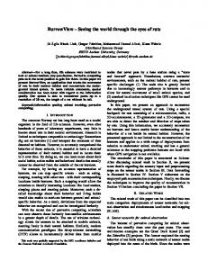
A. Spectrogram Fig. 14. Example spectrograms of the wideband input signal (top) and of the transcoded signal (bottom, G.729.1@14 kb/s).
(e.g., postfiltering and pre-/post-echo reduction). Moreover, additional coding stages in a hierarchical framework, such as transform or wavelet coders, can exploit certain synergies. This has been demonstrated in [18] and [24]. Besides, our technology does not make use of long analysis windows, and thus lower algorithmic delays than for the G.729.1 application are feasible. In principle, the TDBWE could, e.g., use the same delay as the narrowband core codec (15 ms in the G.729 case). Also, even lower bit rates than 1.65 kb/s can be achieved by sacrificing some temporal resolution and by using a predictive quantization which reuses more information from the low-band signal [25]. Such a prediction can even be useful to fill gaps introduced by temporary bandwidth switchings from wide- to narrowband due to bit rate variations [18]. Moreover, it could be shown that it is possible to estimate the TDBWE parameters based on information from the embedded CELP layers with sufficient quality [26]. Such methods enable a wideband rendering for G.729.1 bit rates of 8 and 12 kb/s. Finally, it shall be mentioned that TDBWE uses speechtrained codebooks for the parameter quantization and relies on certain speech characteristics (e.g., a unique pitch period). Hence, the algorithm is, like the G.729.1 CELP layers, not always well suited for music stimuli.
Fig. 14 depicts two spectrograms which are taken from a short utterance of a female American speaker. The first spectrogram shows the wideband input signal, whereas the second one is the G.729.1 output decoded at a received bit rate of 14 kb/s. In the synthetically generated high band, the consistent pitch structure and the properly regenerated energy envelopes are clearly visible. B. Wideband PESQ Measurements The average wideband PESQ [28] scores presented in Table II have been obtained from all American and British English utterances of the NTT corpus [29]. The measurements quantify the quality gain which is obtained through the time envelope shaping (Section III-E) and through the adaptive postprocessing (Section III-G). Therefore, a modified codec version has been examined which skips either the time envelope shaping, the postprocessing, or both modules. The respective wideband PESQ scores indicate that a highquality bandwidth extension can not solely rely on a spectral envelope but should also account for certain temporal signal characteristics. Further, the validity of the TDBWE parameter quantization scheme is shown by comparing the G.729.1 wideband PESQ score with a codec version which uses the “unquantized” TDBWE parameters at the decoder side. Finally, the quality for the case of a transparent (i.e., original) high-band signal is evaluated, where the low-band signal is the output of G.729.1 at 12 kb/s. C. ITU-T Test Results
V. EVALUATION AND TEST RESULTS This section presents an evaluation of the TDBWE algorithm in terms of an example spectrogram of a processed speech signal and measurements of the algorithmic complexity according to [27]. Further, along with wideband PESQ [28] speech quality measurements, subjective listening test results regarding the 14-kb/s mode of G.729.1 are presented. The 14-kb/s mode is relevant for the TDBWE performance. Finally, an extension of G.729.1 to wideband "low-delay" operation is pointed out. All tests have been carried out using the official ITU-T G.729.1 software package comprising a C implementation that uses fixed point arithmetics.
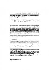
At the ITU-T, a subjective quality assessment has been carried out within the optimization and characterization phase step 1 of the G.729.1 standardization process. An excerpt of the respective listening test results [30, Exp. 1b] is reproduced in Fig. 15. Note that these listening test results not only rate the quality of the high-band signal, but of the entire wideband output signal. In this test, the 14-kb/s mode of the G.729.1 coder is compared with other well-known references which are part of the official requirements from the “Terms of Reference.” The test references are as follows: • ITU-T Rec. G.722 @ 48 kb/s; • ITU-T Rec. G.722 @ 56 kb/s; • ITU-T Rec. G.722.2 @ 8.85 kb/s.
GEISER et al.: BANDWIDTH EXTENSION FOR HIERARCHICAL SPEECH AND AUDIO CODING IN ITU-T REC. G.729.1
Fig. 15. MOS scores for G.729.1 at 14 kb/s under varying input level.
Within the test, the influence of a varying input level has been examined. The tested speech input levels are 36 dBov, 26 dBov, and 16 dBov. Thereby, “ dBov ” is the decibel measure with respect to the overload point as obtained with the P.56 speech voltmeter, cf. [27]. The presented test results have been obtained for clean wideband input speech signals in the English language. The test has been conducted using the absolute category rating (ACR) test methodology [31] where the 32 naïve listeners have been split into four groups of eight persons. Samples from six talkers (three male and three female) with four samples per talker (+one sample for practice) have been presented via supra-aural headphones (closed back, e.g., Sennheiser HD25) with one capsule turned away for mono-aural listening.
2507
Fig. 16. MOS scores for G.729.1 at 14 kb/s under varying frame erasure rate (FER).
TABLE III ALGORITHMIC COMPLEXITY OF G.729.1 (INCL. TDBWE)
TABLE IV ALGORITHMIC COMPLEXITY OF TDBWE
D. Additional Test Results The second subjective listening test—the results are presented in Fig. 16—has been conducted by France Télécom. This test’s objective is to compare the performance of G.729.1 at a bit rate of 14 kb/s with further relevant references. The test laboratory used mono-aural equipment. Twenty-four naïve listeners participated. The test samples were in the French language and comprised four talkers, where four samples per talker were presented. The references for this test are as follows: • ITU-T Rec. G.722.2 @ 12.65 kb/s; • ITU-TRec. G.722.2 @ 23.85 kb/s; • ITU-T Rec. G.722.1 @ 24 kb/s; • ITU-T Rec. G.722.1 @ 32 kb/s. In addition, the influence of frame erasures is assessed. Good performance under frame erasures is crucial for the coder’s targeted application in VoIP networks. In the test, the frame erasure rate (FER) has been varied between 0%, 3%, and 6%. The rather good performance under frame erasures can mainly be attributed to the 450 bit/s of additional FEC information in Layers 2 and 3 of the G.729.1 bitstream (cf. Fig. 1). E. Algorithmic Complexity Tables III and IV list relevant complexity figures for the G.729.1 coder and, particularly, for the TDBWE algorithm.
The algorithmic complexity is—according to [27]—measured in weighted million operations per second (WMOPS) for the worst case that was observed. The complexity figures for the TDBWE part of the codec are actually quite low. For the encoder, the major contributions come from the frequency envelope computation and from the vector quantization of the TDBWE parameters. The decoder complexity is dominated by the modules for excitation generation and frequency envelope shaping, respectively. We additionally observe that the TDBWE complexity is asymmetrically
2508
IEEE TRANSACTIONS ON AUDIO, SPEECH, AND LANGUAGE PROCESSING, VOL. 15, NO. 8, NOVEMBER 2007
allocated to encoder and decoder. However, in contrast to established speech coding algorithms like CELP, the TDBWE decoder part is considerably more complex than the encoder part. The total TDBWE complexity amounts to 3.32 WMOPS. However, for an actual implementation of the algorithm on top of a narrowband codec, at least the band-split and the preprocessing filters (see Figs. 2 and 3) have to be considered in addition to the TDBWE complexity. F. Algorithmic Delay and Wideband Low-Delay Mode The algorithmic delay of the G.729.1 coder is 48.9375 ms with contributions from framing (20 ms), QMF band-split (3.9375 ms), G.729 look-ahead (5 ms), and MDCT-window look-ahead (20 ms). In other words, the TDBWE does not introduce any additional delay into the coder.4 The decoder-side FIR filter delay and, correspondingly, the encoder-side look-ahead of 2 ms in the frequency envelope computation (Section III-A2) are more than compensated for by the G.729 look-ahead (5 ms) in the low-band branch of the coder. Besides its “normal” mode of operation, G.729.1 offers the possibility of “low-delay” operation for its narrowband modes, i.e., at bit rates of 8 and 12 kb/s. In this case, the algorithmic delay of the codec is reduced from 48.9375 to 25 ms (framing plus G.729 look-ahead). For wideband operation, a variant of the G.729.1 14 kb/s mode has been proposed which also offers “low-delay” capability. For this mode of operation, all MDCT domain processing in the TDAC part of the decoder is omitted, and thus the algorithmic delay is reduced by the amount of the MDCT window’s look-ahead, i.e., from 48.9375 to 28.9375 ms. Additionally, the algorithmic complexity is reduced by about 2 WMOPS (cf. Table III). The wideband low-delay mode has been formally evaluated by France Télécom by rerunning the subjective listening tests for the optimization/characterization phase 1 of G.729.1. The tests certify full compliance of the 14-kb/s low-delay mode with the respective “Terms of Reference,” cf. [32]. Yet, this extension of G.729.1 is still under discussion within ITU-T SG16. VI. CONCLUSION This article introduced and characterized the wideband extension layer of ITU-T Rec. G.729.1 which is responsible for a low bit rate (1.65 kb/s) bandwidth extension based on the respective narrowband codec layers. Despite its conceptual simplicity, the implemented algorithm (TDBWE) has proven itself to be a robust and flexible solution for wideband extension of narrowband speech signals. The obtained speech quality is in fact comparable to that of full-fledged wideband speech codecs. The rather low computational complexity figures make the algorithm very suitable for an implementation in portable devices. Besides its application in the G.729.1 coder, our technique can also be applied to a broad variety of existing narrowband codecs. Moreover, the TDBWE scheme still bears potential for 4Strictly speaking, the generated TDBWE excitation signal, which is based on the embedded CELP parameters, is delayed by 2 ms. This slight misalignment in the excitation pattern was accepted in favor of a decreased overall delay. Yet, no drawbacks in terms of speech quality could be found.
further reductions of the consumed bit rate and of its algorithmic delay, rendering it a candidate for a large number of other interesting applications such as [25]. ACKNOWLEDGMENT The authors would like to thank the colleagues from all companies involved in the development of G.729.1 (ETRI, France Télécom, Matsushita Electric Industrial Company, Mindspeed Technologies, Inc., Siemens AG, and VoiceAge Corporation) and in particular Nicolas Duc, who worked as a contractor for France Télécom, for his valuable help in the conversion of several TDBWE components to fixed-point arithmetics. They would also like to thank the reviewers for providing numerous helpful comments on the manuscript. REFERENCES [1] “G.729 Based embedded variable bit-rate coder: An 8–32 kb/s scalable wideband coder bitstream interoperable with G.729,” 2006, ITU-T Rec. G.729.1. [2] “Adaptive multi-rate-wideband (AMR-WB) speech codec: Transcoding functions,” 2005, 3GPP TS 26.190. [3] S. Ragot et al., “ITU-T G.729.1: An 8–32 kb/s scalable coder interoperable with G.729 for wideband telephony and voice over IP,” in Proc. IEEE Int. Conf. Acoust., Speech, Signal Process. (ICASSP), Honolulu, HI, Apr. 2007, pp. IV-529–IV-532. [4] “Coding of speech at 8 kb/s using conjugate-structure algebraic-codeexcited linear-prediction (CS-ACELP),” 1996, ITU-T Rec. G.729. [5] P. Vary and R. Martin, Digital Speech Transmission, Enhancement, Coding and Error Concealment. New York: Wiley, 2006. [6] Y. Agiomyrgiannakis and Y. Stylianou, “Conditional vector quantization for speech coding,” IEEE Trans. Audio, Speech, Lang. Process., vol. 15, no. 2, pp. 377–386, Feb. 2007. [7] P. Jax, “Bandwidth extension for speech,” in Audio Bandwidth Extension, E. Larsen and R. M. Aarts, Eds., New York, Nov. 2004, pp. 171–236, 6. [8] P. Jax and P. Vary, “Bandwidth extension of speech signals: A catalyst for the introduction of wideband speech coding?,” IEEE Commun. Mag., vol. 44, no. 5, pp. 106–111, May 2006. [9] “Extended adaptive multi-rate—wideband (AMR-WB+) codec: Transcoding functions,” 2005, 3GPP TS 26.290. [10] “Enhanced aacPlus general audio codec: General description,” 2006, 3GPP TS 26.401. [11] P. Ekstrand, “Bandwidth extension of audio signals by spectral band replication,” in Proc. 1st IEEE Benelux Workshop on Model-Based Process. Coding of Audio (MPCA), Leuven, Belgium, Nov. 2002, pp. 53–58. [12] “Enhanced aacPlus general audio codec; encoder specification; spectral band replication (SBR) part,” 2004, 3GPP TS 26.404. [13] J. W. Paulus and J. Schnitzler, “16 kbit/s wideband speech coding based on unequal subbands,” in Proc. IEEE Int. Conf. Acoust., Speech, Signal Process. (ICASSP), Atlanta, GA, May 1996, pp. 255–258. [14] A. McCree, “A 14 kb/s wideband speech coder with a parametric highband model,” in Proc. IEEE Int. Conf. Acoust., Speech, Signal Process. (ICASSP), Istanbul, Turkey, Jun. 2000, pp. II-1153–II-1156. [15] R. Taori, R. J. Sluijter, and A. J. Gerrits, “Hi-BIN: An alternative approach to wideband speech coding,” in Proc. IEEE Int. Conf. Acoust., Speech, Signal Process. (ICASSP), Istanbul, Turkey, Jun. 2000, pp. II-1157–II-1160. [16] J.-M. Valin and R. Lefebvre, “Bandwidth extension of narrowband speech for low bit rate wideband coding,” in Proc. IEEE Workshop Speech Coding, Delavan, WI, Sep. 2000, pp. 130–132. [17] J. Schnitzler and P. Vary, “Trends and perspectives in wideband speech coding,” Signal Process., vol. 80, no. 11, pp. 2267–2281, Nov. 2000. [18] B. Geiser, P. Jax, P. Vary, H. Taddei, M. Gartner, and S. Schandl, “A qualified ITU-T G.729EV codec candidate for hierarchical speech and audio coding,” in Proc. IEEE Int. Workshop Multimedia Signal Process. (MMSP), Victoria, BC, Canada, Oct. 2006, pp. 114–118. [19] P. Jax, B. Geiser, S. Schandl, H. Taddei, and P. Vary, “A scalable wideband add-on for the G.729 speech codec,” in ITG-Fachtagung Sprachkommunikation, Kiel, Germany, Apr. 2006, CD-ROM. [20] P. Jax, B. Geiser, S. Schandl, H. Taddei, and P. Vary, “An embedded scalable wideband codec based on the GSM EFR codec,” in Proc. IEEE Int. Conf. Acoust., Speech, Signal Process. (ICASSP), Toulouse, France, May 2006, pp. I-5–I-8. [21] H. S. Malvar, Signal Processing with Lapped Transforms. Norwood, MA: Artech House, 1992.
GEISER et al.: BANDWIDTH EXTENSION FOR HIERARCHICAL SPEECH AND AUDIO CODING IN ITU-T REC. G.729.1
[22] “7 kHz audio coding within 64 kbit/s,” 1988, ITU-T Rec. G.722, in Blue Book, vol. Fascicle III.4 (General Aspects of Digital Transmission Systems; Terminal Equipments). [23] A. V. Oppenheim and R. W. Schafer, Zeitdiskrete Signalverarbeitung (in German), 2nd ed. Munich, Germany: Oldenbourg Verlag, 1995. [24] M. De Meuleneire et al., “A CELP-wavelet scalable wideband speech coder,” in Proc. IEEE Int. Conf. Acoust., Speech, Signal Process. (ICASSP), Toulouse, France, May 2006, pp. I-670–I-700. [25] B. Geiser and P. Vary, “Backwards compatible wideband telephony in mobile networks: CELP watermarking and bandwidth extension,” in Proc. IEEE Int. Conf. Acoust., Speech, Signal Process. (ICASSP), Honolulu, HI, Apr. 2007, pp. IV-533–IV-536. [26] B. Geiser, H. Taddei, and P. Vary, “Artificial bandwidth extension without side information for ITU-T G.729.1,” in Proc. Eur. Conf. Speech Commun. Technol. (Interspeech), Antwerp, Belgium, Aug. 2007, pp. 2493–2496. [27] “Software tools for speech and audio coding standardization,” 2005, ITU-T Rec. G.191. [28] “Wideband extension to Rec. P.862 for the assessment of wideband telephone networks and speech codecs,” 2005, ITU-T Rec. P.862.2. [29] “Multi-lingual speech database for telephonometry,” NTT Adv. Technol. Corp., 1994 [Online]. Available: http://www.ntt-at.com/products_e/speech/ [30] “G.729EV optimisation/characterization phase step 1 test results: Subjective and objective (WB-PESQ) Scores for experiment 1b conditions,” 2006, ITU-T SG16 temp. doc. Q10/16 TD124-WP3. [31] “Methods for subjective determination of transmission quality,” 1996, ITU-T Rec.P.800. [32] “Verification of G.729.1 14k requirements with G.729.1 14k low delay mode,” 2007, ITU-T WP3/16 Doc. Q.10/16 AC-0701–18.
Bernd Geiser (S’06) received the Dipl.-Ing. degree in information and communication technology from RWTH Aachen University, Aachen, Germany, in 2004, where he is currently pursuing the Dr.Ing. degree. He is currently with the Institute of Communication Systems and Data Processing, RWTH Aachen University. His research interests cover the areas of speech and audio coding, artificial bandwidth extension, and backwards-compatible signal enhancement.
Peter Jax (M’02) received the Dipl.-Ing. degree in electrical engineering and the Dr.-Ing. degree, both from RWTH Aachen University, Aachen, Germany, in 1997 and 2003, respectively. From 1997 to 2005, he worked as Research Assistant and Senior Researcher at the Institute of Communication Systems and Data Processing, RWTH Aachen University. Since 2005, he has been head of the Digital Audio Processing Laboratory, Thomson Corporate Research, Hannover, Germany. His research interests include speech enhancement, speech and audio compression, coding theory, and statistical estimation theory.
Peter Vary (SM’04) received the Dipl.-Ing. degree in electrical engineering from the University of Darmstadt, Darmstadt, Germany, in 1972 and the Dr.-Ing. degree from the University of Erlangen-Nuremberg, Germany, in 1978. In 1980, he joined Philips Communication Industries (PKI), Nuremberg, Germany, where he became head of the Digital Signal Processing Group. Since 1988, he has been a Professor at RWTH Aachen University, Aachen, Germany, and head of the Institute of Communication Systems and Data Processing. His main research interests are speech coding, joint source-channel coding, error concealment, and speech enhancement including noise suppression, acoustic echo cancellation, and artificial wideband extension.
2509
Hervé Taddei (M’02) received the Dipl.-Ing. degree in electronics and computer science from the ENSSAT, Lannion, France, in 1995 and the Ph.D. degree in signal processing and telecommunications from the University of Rennes, Rennes, France, in 1999 . His research work was conducted at France Télécom R&D, Lannion, France, and focused on scalable speech and audio coding. In 2000, he worked on joint source and channel coding with Lucent Technologies Bell Labs, Murray Hill, NJ. From 2001 until April 2007, he was with Siemens, Munich, Germany. He is now with Nokia Siemens Networks, Munich, Germany. His research interests cover the area of speech/audio coding and transmission.
Stefan Schandl received the Dipl.-Ing. degree in communications engineering from the Technical University of Vienna, Vienna, Austria, in 1990. He has been working with the DSP Group, Siemens AG, Vienna, Austria, since 1990, with an emphasis on speech coding and speech recognition, i.e., embedded applications for communication equipment and commercial products.
Martin Gartner studied Electrical Engineering at the Technical University in Munich. He worked for Siemens AG, Munich, Germany, and in the U.S. Since 2006, he has been with the Software Development Department, Intertex Data AB, Sundbyberg, Sweden. His main focus is software development for embedded communication platforms.
Cyril Guillaumé was born in Cholet, France, in 1981. He received the Dipl.-Ing. degree in electronics and computer science from ESEO, Angers, France, in 2004 with a major in signal processing and telecommunications. He worked as a contractor for France Télécom R&D/TECH/SSTP during the G.729.1 development phase.
Stéphane Ragot (M’03) was born in Le Mans, France, in 1974. He received the Dipl.-Ing. degree in telecommunications engineering from ENST, Bretagne, France, in 1997 and the M.Sc. and Ph.D. degrees in electrical engineering from the University of Sherbrooke, Sherbrooke, QC, Canada, in 2000 and 2003. He was a Research Assistant and Researcher at the University of Sherbrooke from 1997 to 2003 and a Research Engineer with VoiceAge Corporation, Canada, from 2000 to 2003. In 2003, he joined France Télécom R&D, Lannion, France. He has contributed to the standardization of speech/audio coders, namely 3GPP AMR-WB+, ITU-T G.729.1, and G.722 Appendix IV. His main research interests include source coding and speech/audio processing.