There is a valley at ε = 0.2 which results in best reconstruction performance ... [9] T. Duckett, S. Marsland, and J. Shapiro, âLearning globally consistent maps by ...
BurrowView – Seeing the world through the eyes of rats ´ J´o Agila Bitsch Link, Gregor Fabritius, Muhammad Hamad Alizai, Klaus Wehrle Distributed Systems Group RWTH Aachen University, Germany {jo.bitsch,gregor.fabritius,hamad.alizai,klaus.wehrle}@rwth-aachen.de
Abstract—For a long time, life sciences were restricted to look at animal habitats only post-factum. Pervasive computing puts us in the novel position to gain live views. In this paper we present BurrowView, an application that tracks the movement of rats in their natural habitat and reconstructs the underground tunnel system. To make reliable statements, special consideration has been taken with regard to the information quality. Our system is able to reconstruct paths up to a resolution of 20 cm, the length of a rat without its tail. Keywords-information quality; animal tracking; pervasive computing;
I. I NTRODUCTION The common Norway rat has long been used as a model organism in the field of life sciences. However, even after hundreds of years of laboratory experiments, very little is known about rats in their natural environment. Research is limited to techniques comparable to archeology: Researchers dig out rat burrows [1] and interpret the remnants of then deserted rat habitats. However, to accurately comprehend the behavior of these animals, it is essential to have a detailed representation of their natural habitat and to locate them in it over time. By doing so, we can learn more about their social habits, action radius and behavioral details that usually cannot be observed from the outside of the rat burrows. For example, by having an accurate representation of burrows, we can map specific events - such as eating, sleeping, meeting with other rats - with their corresponding locations inside burrows. Such a mapping would allow the scientists to identify interesting locations like food stashes, sleeping places and meeting points. Moreover, such a detailed knowledge about their behavior and living habits would also enable to extricate between general and animalspecific behavior. As a result, deviations from the expected behavior are recognized and can be investigated furtherly. With the recent rise of pervasive computing, scientists can now observe these formerly inaccessible environments in a greater depth of details. The use of wireless technology allows for sensors to be attached to mobile animals, roaming freely in their natural habitats. Similarly, modern communication paradigms like delay-tolerant networking (DTN) allows to incrementally deliver data from mobile This work was partially supported by the DFG excellence intiative and the German National Academic Foundation.
nodes that never pass by a base station using a ”store and forward” approach. Nonetheless, extreme terrestrial environments, such as the natural habitat of rats, present specific challenges: (1) The node size is greatly limited due to increasingly narrow pathways in burrows and to allow for natural movement of small animal species, and (2) standard localization techniques like GPS cannot be used underground. In this paper, we present an approach to reconstruct the underground tunnel system of rats. Using a special backpack for rats consisting of a microcontroller, radio, a 3D-accelerometer, a 2D-gyrometer and a 3D-compass, we are able to detect the number and direction of steps taken by rats. Using this information, we accurately reconstruct rat burrows and hence enable better understanding of the behavior of a rat inside its natural habitat. However, the presented approach is not limited to the reconstruction of rat burrows and applies to a wide range of deployments from robotics to underwater animal tracking and has a general relevance to the mapping problems humans are faced with when GPS navigation is not available. The remainder of this paper is structured as follows: After discussing related work in Section II, we present more details regarding the sensory input and preprocessing steps on the sensor nodes in Section III. Data forwarding is discussed in Section IV. Section V elaborates on the employed path reconstruction techniques. Finally, we discuss the techniques to improve the quality of reconstruction in Section VI before concluding the paper in Section VII. II. R ELATED W ORK The related work of this paper can be classified into two main categories: deployments of sensor networks for animal observation and simultaneous localization and mapping (SLAM). A. Sensor networks for animal observation The interest of pervasive computing for animal observation has steadily risen over the past years. The most well-known examples are the Great Duck Island [2] and the ZebraNet [3] projects. The former explored the nesting behavior of sea birds using a static network of sensor nodes deployed into the nests of the birds. Since the nodes were
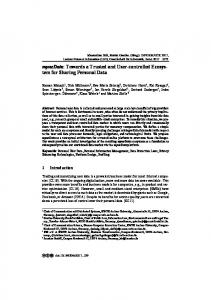
39 mm 2D Gyroscope LiPo-Batteries
110 mm
Figure 1. A Norway rat is wearing a sensor jacket. While this attachment is sufficient for lab environments, outside deployments will require more robust attachment.
not attached to the animals under research, neither tracking, nor dealing with mobility were of any importance. The ZebraNet project equipped zebras with customized sensor nodes. The main focus of this project was indeed the tracking of wild zebras to evaluate their movement patterns and social interactions. With the animals living in the open plains, this deployment used GPS receivers, avoiding much of the challenges of observing underground habitats. In terms of path reconstruction, the DTAG project [4] comes closest to our application. It aims at investigating the behavior of whales, which spend most of their time under water. A recording tag is used to store the current depth and magnetic orientation. Once the tag’s memory is exhausted, it detaches from the whale and floats to the surface for collection. Researchers then evaluate the data on their work stations. While this approach is very elegant for underwater animals, it is not feasible for research on burrowing animals. B. Simultaneous Localization and Mapping Localization and mapping are two very related problems. A location only makes sense in a reference system of a map, while a map represents the locations of certain well known points. Simultaneous localization and mapping (SLAM) is an active research in robotic research. Durrant-Whyte and Bailey [5], [6] recently presented a detailed description of the problem and gave an overview of approaches and recent developments in this field. The main approach is to find positions that are easy to recognize, so called landmarks. Other locations are then described in relation to these landmarks. Examples of these can be optical features, e.g. a special marking, or topological features, e.g. a sharp left turn followed by a right turn. To cope with noise and distortions during measurement and landmark recognition, extended Kalman filters(EKF) are applied, leading to a class of algorithms called EKF-SLAM. Another method is to apply the Rao-Blackwellized particle filter, resulting in the algorithm class of FastSLAM. In contrast to the existing work, we propose a system based on sensor nodes, which traces the movement in the absence of GPS and combines these traces into a consistent map.
Microprocessor + 3D Accelerometer + 2D Compass + Voltage Regulator
Figure 2. The sensor jacket consists of several sensors. Due to their nature, they need to be in specific positions with respect to their carrier. The jacket is therefore designed to hold the sensors at well-specified locations.
III. S ENSORY I NPUT AND P REPROCESSING Tracking the six degrees of freedom of an animal (i.e. positions and rotations) is often achieved using a combination of inertial measurements, satellite navigation systems and magnetic sensors. Satellite based localization however, is not available to us due to the underground nature of the habitat. The radio signals from the satellite simply do not reach the antennas of our nodes under several centimeters of earth. Special radio equipment on the other hand would require more computing and battery power and result in a heavier and bulkier equipment attached to the rats, impeding their natural movement. We therefore developed a sensor backpack based on inertial sensors, a magnetometer, and a gyroscope, which can be seen in Fig. 1 and Fig. 2. These are attached to the rats’ torso via a small jacket worn by the rats on which the backpack is fixed using Velcro. Although implantation of these sensor into the body of animal would be preferred, this is not yet feasible due to the size of the sensors when compared to the size of the rats. Our approach draws on from the ideas of pedestrian navigation [7], which measures human stepping for distance measurement and combines it with azimuth measurements from a fusion of compass and gyrometer readings. The speed or step length can therefore be estimated from the step duration, frequency and timing. Thus we distinguish two main issues in estimating the position of a rat: Estimating the velocity at which it moves and its orientation over time. Knowledge of these two quantities allows us to calculate the position of the rat in time, which in turn yields important behavioral information such as activity profiles or the layout of the burrow system. A. Pseudo steps Although there are similarities between our system and the existing pedestrian navigation systems, both are optimized for different scenarios. In the following we identify the main differences between our approach and step counting with human subjects.
fast
8
stop
slow
7
Reconstructed path starting on the left
6
Reconstructed path starting on the right
position
5 4
Tunnel system
3
Averaged Trajectories
2 Trigger signal Acceleration X Acceleration Y Acceleration Z Position of rat
1 0
896
898
900 902 time [s]
904
1m
906
Figure 4. Over the course of several test runs in an artificial rat burrow in the laboratory, the path reconstruction algorithms can be tested. The left side shows bigger errors due to local disturbances in the magnetic field due to near-by laboratory equipment.
Figure 3. This graphs represents exemplary raw data collected in a linear tube. The movement is clearly subdivided into parts of different activity: faster movement, a stopping phase and a slower movement phase.
C. Integration with Heading Estimation •
•
Accelerometers cannot be attached to the rats feet as they are in some pedestrian navigation systems. Thus, the use of the term step is not accurate. The periodicity of the signal does not correlate with individual steps of one paw, but with a cycle of four steps. In fact, the number of actual steps in a cycle is neither relevant nor can it be inferred from the signals. Hence, we often refer to one cycle as a pseudo-step. Our setup has a lower ratio of step time to available sample period, making period detection more difficult. In human step counting, it is possible to detect the phases of a step with a signal that offers strong features and thus reliable time measurements and even context information. In comparison, our signal offers fewer features for time-domain measurements.
Bearing these constraints, we developed a method that estimates the velocity of rats by measuring the time between peaks in the signal of the accelerometer in the transverse plane of the rat. Laboratory experiments have shown that the time between two peaks correlates with the velocity, under the knowledge that the rat is actually walking . B. Implementation The pseudo-step detection is performed by the hardware, using one channel of an ADXL330 accelerometer, the signal is fed to an analog low-pass filter and is passed to a comparator, sampled at 10 Hz. The rats were free to move around in an artificial burrow constructed from drain pipes and fitted with light barriers, allowing to reconstruct the velocity at which the rats move. Example data is presented in Fig. 3. Measuring the time between pseudo-steps and calculating the estimated speed is achieved in software. When no stepping is measured, the system is able to record the estimated elevation (or pitch) angle relative to gravity, a feature that is useful in characterizing rats exploratory habits.
It is a common practice to combine gyrometer and compass readings to yield improved heading estimation [7]. In our case, the processing was simplified in order to save computational power without compromising the desired accuracy, i.e., by replacing the commonly used Kalmanfilter based integration with a simpler approach (e.g. spring relaxation). In order to prove the viability of our approach, the previously described test setup with drain pipes was expanded to include turns. Again, the pipes were fitted with light barriers to verify the rats actual position at key points. All the experiments described until now had been carried out indoors, i.e., inside a concrete building. As a result, the earths magnetic field is disturbed at the experimental site: In some places the disturbance is up to 55 ◦ . Since our final deployment scenario is outdoors, we introduced a correction for the local (indoor) disturbances of the magnetic field. The field was characterized for the whole of the experimental site and for each compass reading, i.e., the sample was corrected according to the current location. This correction would not be required in an eventual outdoor deployment. Fig. 4 shows the average over more than 60 runs of two rats over 20 days in the setup. It clearly shows that, while there is room for improvement, the system could be used to study the layout of rat burrows, if enough data is gathered. The striking differences in accuracy on the left of the setup, as compared to the right side, can be attributed to intricacies in the magnetic field disturbances that could not be corrected by our approach. Right now, we focus our work on context recognition. The animals display a wide range of behavior aside from running which affect the accelerometer readings, e.g. rats may stand on their hind legs in an effort to explore the environment. Differentiating between these different states is the main reason for using 3-D acceleration measurements, even though lateral measurements are sufficient to characterize stepping.
IV. DATA F ORWARDING The common Norway rat, similar to humans, is a social animal. To deal with the challenges faced by the underground scenario, we have to make use of these social properties, employing a routing scheme called SimBetAge, which we recently proposed in [8]. Analyzing the temporal change in the social network, we do not only gain valuable behavioral information, but also improve routing performance by a factor of two compared to previous approaches. The project is still in an early stage, so we were not yet able to complete experiments in an outdoors setting. The results from the previous section are from laboratory experiments. However, to be able to develop and evaluate path reconstruction algorithms properly, we built a simulator based on our laboratory experience. This provides us with a number of test cases, while at the same time allowing us to accurately judge the reconstruction quality, as the input burrow systems are known. V. R ECONSTRUCTION With the gathered data it is possible to reconstruct trails of the rats with an estimate of a step’s length, and using the proximity information we can determine meeting points between them. These trails are tied together at the meeting points and error compensation is performed using a flexible spring-like model. By applying several algorithms to optimize the data, one can get an approximate reconstruction of the burrow parts that are currently used by rats and therefore covered by the data. A. Problem Area The task of creating a map of the burrow is similar to the field of simultaneous localization and mapping (SLAM) [5] in robotic science: At the beginning of the mapping process, neither the location of the mapping agent, the sensor mote in our case, nor a map of the environment where it is located in, the burrow, is known. To solve this problem, each agent tries to determine the change of its location while moving and tracking this movement within its own coordinate system. If there are several agents that map the same environment, the trails of all agents are merged together. B. Algorithmic Basis We render each data set that has been recorded by a sensor mote and transmitted to the base station into a geometric representation called pathlet. This pathlet represents a part of the trail that has been traversed by the rat. Pathlets are subject to certain distortion and inaccuracies because the data is gathered by sensors which are not guaranteed to output completely accurate data. Moreover, we use an estimate of a rat step’s length to render the sensor data to a pathlet which itself introduces uncertainty.
(a) Before filtering
(b) After filtering
Figure 5. Sensor noise and redunt paths can be filtered out using sphere filtering. Vertices within an ε-sphere of each other are combined.
1) Converting Data into Pathlets: Every time the rat takes a step, the mote’s step detector records the current time and heading using the 3D compass. If there are other motes in radio range, their ID is recorded, too. Therefore, such a sensor reading (SR) represents one step with the corresponding direction. A consecutive set of sensor readings is called sensor reading set (SRS). A pathlet is the geometric representation of a walked path based on the processed data of a sensor reading set. It is a simple, undirected graph, that is initially created by concatenating the recorded steps according to an estimated step length in the direction of the corresponding heading. For each SR of the SRS, a vertex in the graph is created at the position p~ where heading ~h and estimated step length s from the position of the previous vertex points to: p~i+1 = p~i + ~h · s, where i denotes the number of vertices. The position of the first vertex is initialized with ~0. Between consecutive vertices, we create edges so that the graph becomes a representation of the walked path. As a property of each vertex v, the proximity information of the SRS is stored, denoted by Proximity(v) ⊂ N, as well as the timestamp, denoted by Timestamp(v). Note that the recording agent never appears in its proximity. Every edge e stores the heading h(e) and the estimated step length s(e) that resulted in its creation as a property. The pathlet itself is created from an SRS that originated from a mote. The ID of the mote that recorded a particular pathlet P is denoted by ID(P ). This information is needed later in order to connect pathlets from different motes. 2) Postprocessing Pathlets: Due to the sensory origin of the pathlets, their reconstruction is error-prone. There are two major sources of these errors: (1) Inaccurate data produced by the sensors, and (2) multiple paths traversed by rats during a sensor recording. As a result, it may introduce redundant paths. To handle these errors or to distribute them over the whole graph, we postprocess the pathlets using a filter pipeline. The sensor noise can be tackled by applying angle weighted smoothing. Similarly, to filter out redundant paths, we used a graph processing method called sphere filtering. The effects of this filtering are shown in Fig. 5. The easiest way to remove noise from a data set is to smooth it. Smoothing a path means to move every vertex
v towards the midpoint m(v) ~ = (~u + w)/2 ~ of its two adjacent vertices u and w. This movement is expressed as a translation ~vk+1 = ~vk + ~t(v) (where k denotes the iteration step) along the translation vector ~t(v). By applying ~t(v) completely, one would achieve an intense smoothing (i.e. more than it is desired in this case). Therefore, ~t(v) is weighted to reduce the smoothing impact on the graph’s structure. To preserve the coarse graph structure and to remove spikes in the path, we weigh ~t(v) by only taking a fraction of it: ~ ~tf inal (v) = q t(v) 1 + ||~t(v)|| A rat may walk through the same tunnel more than once, either because it is walking back or because it is walking along the same way again. As a result, the reconstructed path may contain multiple parts that represent the same tunnel. Assuming exact sensor data, these paths would lie exactly on top of each other, but this is not the case. To achieve a single representation for a tunnel, we use the following sphere filtering method. In this contraction based method, sphere with radius � is put around a vertex v. All vertices within this sphere Sε (v) except one representative vertex will be removed, while preserving the connectivity to the vertices outside the sphere. The representative P vertex r is the vertex nearest to the center of gravity |Sε1(v)| u∈Sε (v) ~u of all vertices within the sphere. All vertices outside the sphere that have an edge with a vertex inside the sphere are linked by an edge r to keep the connectivity intact. The contraction begins with a central sphere and is iterated until there is no sphere with more than one vertex is left. Using a combination of these two methods for filtering, we get two parameters for the filter pipeline: The count of smoothing iterations and the radius ε of the spheres. Variations of these parameters impact the results of the filtering, and therefore, they have to be chosen carefully. At this stage of the project we chose them manually, however, the possibilities of choosing them automatically are discussed in section VI. C. Merging Pathlets Together Every pathlet represents the reconstructed path of a data set that has been collected at the base station. Using the properties for vertices described in section V-B1, we can connect the pathlets at meeting points between rats. The points occur if the motes are within vicinity of each other and can be determined by using the Proximity(v) and Timestamp(v) information. We call possible meeting points as anchors. An anchor is a vertex of a pathlet with nonempty proximity. Two anchors a1 ∈ P1 , a1 ∈ P1 of two different pathlets P1 and P2 are compatible, iff their timestamps match, i.e. their difference is below a certain threshold, and ID(a1 ) ∈ Proximity(a2 ) ∧ ID(a2 ) ∈
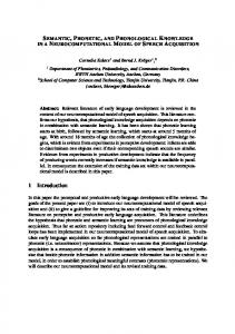
Figure 6. An example of a burrow reconstruction based on a map from [1]. The reconstruction fits the original burrow structure accurately.
Proximity(a1 ). The set of compatible pathlets of two anchors is denoted as AC (P1 , P2 ) and two pathlets are compatible iff AC (P1 , P2 ) 6= ∅. The compatibility of all pathlets is described as a simple undirected graph, where the vertices denote pathlets and compatibility between them is denoted by edges. This graph is not necessarily connected, therefore, we take the biggest connected subgraph to start burrow reconstruction. If two pathlets have compatible anchors, they can be merged to become a new pathlet that is a combination of both. To achieve this, we initially transform P1 to be in alignment with P2 . Because we use compass data as a source of pathlet creation, we can ignore the rotation and focus on the translation vector ~t, which is calculated by the mean distance vector of all compatible anchors: X 1 ~t = ~a2 − ~a1 |AC (P1 , P2 )| (a1 ,a2 )∈AC (P1 ,P2 )
Due to the noisy nature of the pathlets we can not assume that this initial alignment is perfect. To accurately combine the pathlets, we use a relaxation algorithm, like the one mentioned in [9], where we treat edges as springs with an intended length and achieve a global minimum tension in the system by applying the relaxation iteratively. Therefore, we span edges with an intended length of 0 between compatible anchors and tie the pathlets together as accurate as possible during the relaxation process. After merging all pathlets together and performing the relaxation afterwards, we get a representation of the burrow based on the sensor data and the connectivity information. The quality of this reconstruction is dependant on the quality of the original data and the improvement offered by filtering pipeline based on the chosen parameters. An example of a reconstruction in comparison to the original burrow from [1] is shown in Fig. 6.
VI. Q UALITY OF R ECONSTRUCTION To measure the quality of the reconstruction, we use a combination of alignment and comparison techniques that are applied to the graph representation of the original and the reconstructed burrow. As described in section IV, the second part of this paper is based on simulation, so we actually have the original burrow available. The idea is to first align both graphs - the original and the reconstructed one - to overlap identical parts and measure the remaining differences. As a first step, both graphs are converted into point clouds, i.e. PO and PR . We minimize the inaccuracy introduced during this conversion by representing long edges in the graph by a chain of points. Hence, the basic structure of the graph is preserved. For alignment, we use the Trimmed Iterative Closest Point algorithm (TrICP)[10], which, despite only finding a local optimum of the alignment, performs adequately in our case. The distance of point sets in space can be measured by using the Hausdorff Distance dH , which is not symmetric, i.e. dH (A, B) 6= dH (B, A). We exploit this asymmetry to gain two different kinds of measurements: (1) dH (PO , PR ) implies the reconstruction amount, i.e. how much of the original burrow is covered by the reconstruction. This value is highly dependent on the original data which is not under our control, and (2) dH (PR , PO ) is a measurement for the reconstruction error, i.e. the parts of the reconstruction falsely introduced in the reconstruction, and therefore, important for our evaluation. In our basic filter pipeline, the smoothing amount and the radius of the epsilon spheres are the two main parameters that affect the information quality. By varying these parameters on the same set of data, we observed that the smoothing amount does not have significant impact on the results. However, the radius of the sphere is essential for improving the quality and impairment of the data. Fig. 7 shows that when a stronger filtering is applied to undistorted data, the reconstruction error increases. Similarly, if the same filtering is applied to the distorted data, the reconstruction error decreases to a certain level, unless the error that is introduced by the filtering outweighs the improvement. Finding this optimum setting of filter parameters automatically, is a future work. We used maps of rat burrows taken by Calhoun [1] as a habitat for a simulated rat population to produce artificial sensor data. Depending on the amount of distortion of the data, we achieved a reconstruction error between 0.2 to 0.5 meters. This is well in par to make reliable statements about the biological relevance of different locations. VII. C ONCLUSION In this paper, we demonstrated that the reconstruction of 3D paths using restricted devices like sensor nodes is possible at an acceptable quality of reconstruction using carefully designed filtering and postprocessing. Our future
(a) Low distorted data
(b) Heavily distorted data
Figure 7. Smoothing iterations s and sphere radius ε impact on reconstruction quality. There is a valley at ε = 0.2 which results in best reconstruction performance, even with heavily distorted data.
work will focus on the automatic determination of reconstruction parameters and a better step length estimate. Also, to reduce the number of bytes to be transmitted, we will move more parts of the processing pipeline to the nodes. Our approach therefore proves very useful, enabling a new class of applications on the interface between pervasive computing and biology. R EFERENCES [1] J. Calhoun, The Ecology and Sociology of the Norway Rat. U.S. Dept. of Health, Education, and Welfare, Public Health Service, 1963. [2] R. Szewczyk, J. Polastre, A. Mainwaring, and D. Culler, “Lessons from a Sensor Network Expedition,” in Proc. of European Workshop on Wireless Sensor Networks, 2004. [3] P. Juang, H. Oki, Y. Wang, M. Martonosi, L. Peh, and D. Rubenstein, “Energy-efficient computing for wildlife tracking: Design tradeoffs and early experiences with zebranet,” in Proc. of conference on Architectural support for programming languages and operating systems (ASPLOS), 2002. [4] M. Johnson and P. Tyack, “A Digital Acoustic Recording Tag for Measuring the Response of Wild Marine Mammals to Sound,” IEEE Journal of Oceanic Engineering, 2003. [5] H. Durrant-Whyte and T. Bailey, “Simultaneous localization and mapping: Part i,” Robotics & Automation Magazine, IEEE, vol. 13, no. 2, pp. 99–110, 2006. [6] T. Bailey and H. Durrant-Whyte, “Simultaneous localization and mapping (slam): Part ii,” Robotics & Automation Magazine, IEEE, vol. 13, no. 3, pp. 108–117, 2006. [7] L. Fang, P. Antsaklis, L. Montestruque, M. McMickell, M. Lemmon, Y. Sun, H. Fang, I. Koutroulis, M. Haenggi, M. Xie et al., “Design of a wireless assisted pedestrian dead reckoning system-the NavMote experience,” IEEE Transactions on Instrumentation and Measurement, vol. 54, no. 6, pp. 2342–2358, 2005. ´ Bitsch Link, N. Viol, A. Goliath, and K. Wehrle, [8] J. A. “SimBetAge: dealing with change in social networks for pocket switched networks,” in 1st ACM Workshop on Userprovided Networking, Rome, Italy, 12 2009. [9] T. Duckett, S. Marsland, and J. Shapiro, “Learning globally consistent maps by relaxation,” in Robotics and Automation, 2000. Proc. ICRA ’00. IEEE International Conference on, vol. 4, 2000, pp. 3841–3846 vol.4. [10] D. Chetverikov, D. Svirko, D. Stepanov, and P. Krsek, “The trimmed iterative closest point algorithm,” in ICPR ’02: Proc. of the 16th IEEE Int. Conf. on Pattern Recognition Vol. 3. Washington, DC, USA, 2002, pp. 30 545+.