International Journal of Innovation, Management and Technology, Vol. 1, No. 3, August 2010 ISSN: 2010-0248
Battery Energy Storage System for Variable Speed Driven PMSG for Wind Energy Conversion System Rajveer Mittal, K.S.Sandu and D.K.Jain
Abstract—The energy demand around the world increases; the need for a renewable energy source that will not harm the environment has been increased i. e. Wind power is one of them. There are many loads (such as remote villages, islands, ships etc) that are away from the main grid. They require stand-alone generator system (which can provide constant nominal voltage and frequency) to provide for their local electrification. Wind power can be used in off-grid systems, also called stand-alone systems, not connected to an electric distribution system or grid. The power conversion unit features a wind-turbine-driven PMSG, a diode rectifier, a buck-boost dc/dc converter, a battery bank, and a dc/ac inverter. In this paper, a distributed generation based on stand alone wind energy conversion system (WECS) using a variable speed permanent magnet synchronous generator (PMSG) is proposed with PWM rectifier and a battery for storing the extra wind energy. The topology for the same has been demonstrated using MATLAB Simulink based simulations. Index Terms—Wind energy conversion system, Isolated system, battery bank, Permanent magnet synchronous generator. I.
INTRODUCTION
Renewable energy sources including wind power offer a feasible solution to distributed power generation for isolated communities where utility grids are not available. In such cases, stand-alone wind energy systems (i.e., systems not connected to the utility grid) can be considered as an effective way to provide continuous power to electrical loads. One of the most promising applications of renewable energy generation lies in the development of power supply systems for remote communities that lack an economically feasible means of connecting to the main electrical grid. For isolated settlements located far from a utility grid, one practical approach to self-sufficient power generation involves using a wind turbine with battery storage to create a stand-alone system. If wind conditions are favorable, these stand-alone wind energy systems usually can provide communities with electricity at the lowest cost.Stand-alone wind energy systems often include batteries, because the available wind Rajveer Mittal is with the Department of Electrical and Electronics Engineering, Maharaja Agrasen Institute of Technology, Rohini,Delhi , India (e-mail :
[email protected],
[email protected] ) K.S Sandhu is with the Department of Electrical Engineering, National Institute of Technology, Kurukshetra, Haryana, India. (e-mail l:
[email protected].). D. K. Jain is with the Guru Prem Sukh Memorial College of engineering under GGSIP University , Delhi, India. (e-mail:
[email protected]).
does not always produce the required quantities of power. If wind power exceeds the load demand, the surplus can be stored in the batteries [1-2]. The function of an electrical generator is providing a mean for energy conversion between the mechanical torque from the wind rotor turbine, as the prime mover, and the local load or the electric grid. Different types of generators are being used with wind turbines. Small wind turbines are equipped with DC generators of up to a few kilowatts in capacity. Modern wind turbine systems use three phase AC generators. The common types of AC generator that are possible candidates in modern wind turbine systems are as follows: • Squirrel-Cage rotor Induction Generator (SCIG), • Wound-Rotor Induction Generator (WRIG), • Doubly-Fed Induction Generator (DFIG), • Synchronous Generator (With external field excitation), • Permanent Magnet Synchronous Generator (PMSG). For assessing the type of generator in WECS, criteria such as operational characteristics, weight of active materials, price, maintenance aspects and the appropriate type of power electronic converter are used. Historically induction generator (IG) has been extensively used in commercial wind turbine units. Asynchronous operation of induction generators is considered an advantage for application in wind turbine systems, because it provides some degree of flexibility when the wind speed is fluctuating. There are two main types of induction machines: squirrel cage and wound rotor. The induction generator based on Squirrel-Cage rotor (SCIG) is a very popular machine because of its low price, mechanical simplicity, robust structure, and resistance against disturbance and vibration. The wound-rotor is suitable for speed control purposes. By changing the rotor resistance, the output of the generator can be controlled and also speed control of the generator is possible. Although wound rotor induction generator has the advantage described above, it is more expensive than a squirrel-cage rotor. The induction generator based on wound rotor is the doubly fed induction generator (DFIG), which is a kind of induction machine in which both the stator windings and the rotor windings are connected to the source. The rotating winding is connected to the stationary supply circuits via power electronic converter. The advantage of connecting the converter to the rotor is that variable-speed operation of the turbine is possible with a much smaller and therefore much cheaper converter. The power rating of the converter is often about 1/3 the generator rating. 300
International Journal of Innovation, Management and Technology, Vol. 1, No. 3, August 2010 ISSN: 2010-0248
Another type of generator that has been proposed for wind turbines in several research articles is synchronous generator. This type of generator has the capability of direct connection (direct-drive) to wind turbines, with no gearbox. This advantage is favorable with respect to lifetime and maintenance. Synchronous machines can use either electrically excited or permanent magnet (PM) rotor. The PM and electrically-excited synchronous generators differ from the induction generator in that the magnetization is provided by a Permanent Magnet pole system or a dc supply on the rotor, featuring providing self-excitation property. Self-excitation allows operation at high power factors and high efficiencies for the PM synchronous generators. It is worth mentioning that induction generators are the most common type of generator use in modern wind turbine systems [3-9]. A comparison between the variable speed wind turbine and the constant speed wind turbine shows that variable speed reduce mechanical stresses: gusts of wind can be absorbed, dynamically compensate for torque and power pulsations caused by back pressure of the tower. This backpressure causes noticeable torque pulsations at a rate equal to the turbine rotor speed times the number of rotor blades. The used of a doubly fed induction generator in WECS with the rotor connected to the electric grid through an AC-AC converter offers the following advantages: only the electric power injected by the rotor needs to be handled by the convert , implying a less cost AC-AC converter; improved system efficiency and power factor control can be implemented at lower cost, the converter has to provide only excitation energy . Hence, taking advantage of power electronic advances in recent years, WECS equipped with doubly fed induction generator systems for variable speed wind turbine are one of the most efficient configurations for wind energy conversion.[6-8]
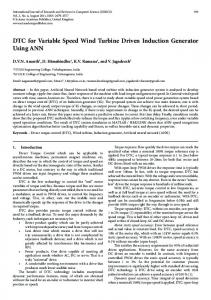
II. PERMANENT MAGNET GENERATOR Figure 1 shows the cross-section of a typical Permanent Magnet Generator (PMG). The PMG differs from the Induction Generator in that the magnetization is provided by a Permanent Magnet Pole System on the rotor, instead of taking excitation current from the armature winding terminals, as it is the case with the Induction Generator. This means that the mode of operation is synchronous, as opposed to asynchronous. That is to say, in the PMG, the output frequency bears a fixed relationship to the shaft speed, whereas in the mains connected IG, the frequency is closely related to the network frequency, being related by the slip. These differences will be discussed at length. However, it must be recognized at the outset that the differences have a significant effect on the operating characteristics and performance of the two generator types.
Figure 1. Cross-section of typical conventional Permanent Magnet Generator.
Permanent magnet machines may be set in several categories, those with surface mounted magnets, those with buried magnets, those with damper windings, etc., etc. All categories where data was found were considered, as each has some special features to offer [3]. The advantages of PM machines over electrically excited machines can be summarized as follows according to literatures: Higher efficiency and energy yield, No additional power supply for the magnet field excitation, Improvement in the thermal characteristics of the PM machine due to the absence of the field losses, Higher reliability due to the absence of mechanical components such as slip rings, Lighter and therefore higher power to weight ratio. However, PM machines have some disadvantages, which can be summarized as follows: High cost of PM material, Difficulties to handle in manufacture, Demagnetization of PM at high temperature. In recent years, the use of PMs is more attractive than before, because the performance of PMs is improving and the cost of PM is decreasing. The trends make PM machines with a full-scale power converter more attractive for direct-drive wind turbines. Considering the performance of PMs is improving and the cost of PM is decreasing in recent years, in addition to that the cost of power electronics is decreasing, variable speed direct-drive PM machines with a full-scale power converter become more attractive for offshore wind powers. On the other hand, variable speed concepts with a full-scale power converter and a single- or multiple-stage gearbox drive train may be interesting solutions not only in respect to the annual energy yield per cost but also in respect to the total weight. For example, the market interest of PMSG system with a multiple-stage gearbox or a single-stage gearbox is increasing [8-11]. III. TOPOLOGIES FOR ISOLATED OPERATION OF VARIABLE SPEED WIND DRIVEN PMSG Variable speed use is good for extracting more prime mover power as in wind turbine or for providing optimum 301
International Journal of Innovation, Management and Technology, Vol. 1, No. 3, August 2010 ISSN: 2010-0248
efficiency for the prime mover by increasing its speed with power. Variable speed also allows for a more flexible generator system. For wind turbines, a battery may be added to store the extra wind energy that is not momentarily needed for the existing loads or local power grids [10-12]. At variable speed, the DC link voltage is maintained constant by exchanging power with battery as shown in Fig. 1 Fig.1 PMSG with PWM rectifier with battery for storing the extra wind energy
IV. MATLAB SIMULATION OF THE PROPOSED TOPOLOGY The MATLAB Simulation of proposed topology has been shown in the Fig.2. The matlab simulink tool box simpower has been used for getting the required results Timer [Wr] [Theta ]
[Iabc _rotor] [Vabc_rotor]
[Pulses]
[IL] g
m
C
E
[Pulse2]
C
b c
+ -
[Vin ]
v
+v -
[Vdc]
C
Ideal Switch
+
Fo=100 H
[VdcO] + v -
-
Breaker2
g
[V]
A
30uF -
+ v -
B
V+
C
+ v -
g C
B
vbc 1
m E
Ba
+
[IB]
m E
B
A
2
i + -
g C
A m
AV Ia
1
Breaker1
IGBT Inverter Tm
m
[I]
i -
Wind1
[Pulse1]
+ v -
g
+
2
Uref Pulses
+
[Vref]
i -
Battery 1 [IG]
i + -
[ILB ]
IGBT Inverter 1 V-
[Vl] i + -
Fig.2. MATLAB Simulated model of PMSG connected to local Load
V. MODELING OF PROPOSED SYSTEM A. Modeling of System This section includes modeling of supply system (PMSG), load, controller etc. The relevant mathematical analysis is illustrated as follows. B. Modeling of Supply system The supply system consists of three-phase (PMSG) system, diesel engine and governor blocks. The model of permanent magnet synchronous generator (PMSG) is realized byconsidering fixed excitation of an alternator. The mathematical representation of all these are given below. C. Modeling of Permanent Magnet Synchronous Machine The permanent magnet synchronous machine block operates in generating or motoring modes. The operating mode is dictated by the sign of the mechanical power (positive for generating, negative for motoring). The electrical part of the machine is represented by a sixth-order state-space model. The model takes into account the dynamics of the stator and damper windings. The equivalent
circuit of the model is represented in the rotor reference frame (d-q frame). The following equations are used to express the model of the PMSG as: Vd = Rsid + pd – wr q (1) Vq = Rsiq + pq + wr d (2) V’fd = R’fdi’fd + p’fd (3) V’kd = R’kdi’kd + p’kd (4) V’kq1 = R’kq1i’kq1 + p’kq1 (5) V’kq2 = R’kq2i’kq2 + p’kq2 (6) where d = Ld id + Lmd ( i’fd + i’kd) (7) q = Lq iq + Lmq i’kq (8) ’fd = L’fd i’fd + Lmd ( id + i’kd) (9) ’kd = L’kd i’kd + Lmd ( id + i’fd) (10) 302
International Journal of Innovation, Management and Technology, Vol. 1, No. 3, August 2010 ISSN: 2010-0248
’kq2 = L’kq2 i’kq2 + Lmq iq (11} where the subscripts used are defined as: d, q: d and q axis quantity, r, s: Rotor and stator quantity, l, m: Leakage and magnetizing inductance, f, k: Field and damper winding quantity. Rs represents stator resistance, Lls stator leakage inductance, Lmd and Lmq represent d-axis and q-axis magnetizing inductances. Rf’ denotes field resistance and Llfd’ leakage inductance, both referred to the stator. Damper d-axis resistance Rkd’ and leakage inductance Llkd’, Damper q-axis resistance Rkq1’ and leakage inductance Llkq1’ and the q-axis resistance Rkq2’ and leakage inductance Llkq2’ All these values are referred to the stator. All rotor parameters and electrical quantities are viewed from the stator and are identified by primed variables. The simplified synchronous machine block implements the mechanical system described by: ∆w(t)= ∫(Tm – Te)dt / (2H) – Kd∆w(t) (12) w(t) = ∆w(t) + wo (13) D. Excitation System The excitation system block is a Simulink system implementing an IEEE Type I synchronous machine voltage regulator combined to an exciter. The basic elements that form the excitation system block are the voltage regulator and the exciter. The exciter is represented by the following transfer function between the exciter voltage Vfd and the regulator’s output Ef. Vfd/Ef = 1/(Ke + sTe) (14) where Ke represents exciter gain, Te exciter time constant. The block uses actual terminal voltage, desired value of terminal voltage and outputs appropriate field voltage to be applied to synchronous alternator. For simulation of PMSG, the excitation is kept constant at 1.0 p.u. in this model of synchronous generator. E. Wind Turbine Modelling This block implements a wind energy conversion system. The inputs are actual and desired speed and the output of the block is mechanical power (Pω). The amount of power harnessed from the wind of velocity v is as follows. Pω=1/2 ρACpν3
(15)
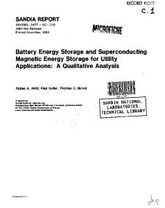
Where Pω= wind power in watts ρ = air density in kg/m3 A= swept area in m2 Cp=power coefficient of wind turbine ν= wind speed in m/s VI. SIMULATION RESULTS Performance of PMSG with PWM rectifier with battery for storing the extra wind energy The wind driven PMSG is run at 450 rpm. The out voltage is 150 V at 60 hertz. This variable voltage and variable frequency output is converted to constant voltage and
constant frequency source. The Fig.3 show the Variation of load voltages, load currents, generator power, battery power, , load power battery current & d c voltage. The rating of the PMSG is given in the Appendix
VII. CONCLUSION This paper discuss a distributed generation based stand alone wind energy conversion system (WECS) using a variable speed permanent magnet synchronous generator (PMSG) with PWM rectifier and a battery for storing the extra wind energy. According to the proposed topology, Battery energy storage system provides power balance between the generated power and the load. The power mismatch is absorbed by the BESS APPENDIX Permanent Magnet Synchronous Generator: 3-Phase , 300 V, 60 Hz, 3000 rpm, 4-pole Electromagnetic Torque : 0.8 Nm : 18.7 Ω Stator Resistance(RS) Inductance : Ld(H) = Lq(H) : 0.02682 H Flux induce by magnets : 0.1717 wb REFERENCES [1]
Bhim Singh and Gaurav Kumar Kasal, “Solid-State Voltage and Frequency Controller for a stand alone wind power generating system,” IEEE Trans. Power Electronics, vol. 23, no.3, pp.1170–1177, 2008. [2] Bhim Singh and Gaurav Kumar Kasal, “Voltage and Frequency Controller for a 3-Phase 4-Wire Autonomous Wind Energy Conversion System” accepted for publication in IEEE Trans. on Energy Conversion. [3] Arkadan,A.A., Hijazi,T.M., & Demerdash,D.A. (1989). Computer-aided modeling of a rectified DC load-permanent magnet generator system with multiple damper windings in the natural abc frame of reference. IEEE Transactions on Energy Conversion, 4(3), 518-525. [4] Ghosh and G. Ledwich, Power Quality Enhancement Using Custom Power Devices. Kulwer Academic, 2002. [5] Gipe, P. Wind power’, Chelsea Green Publishing Company, Post Mills, Vermount, USA,1995. [6] Rai, G.D. (2000) ‘Non conventional energy sources’, Khanna Publishers, 4th Edition, New Delhi (India) [7] Bansal, R.C., Bhatti, T.S., and Kothari, D.P. ‘On some of the design aspects of wind energy conversion systems”, Int. Journal of Energy Conversion and Management, Nov. Vol. 43, No. 16, pp. 2175-2187,2002. [8] Singh, B. ‘Induction generator-a prospective’, Electric Machines and Power Systems, Vol. 23, pp. 163-177,1995. [9] Zouaghi, “Variable Speed Drive modelling of Wind Turbine Permanent Magnet Synchronous Generator,” ICREP’04 International Conference on Renewable Energy and Power Quality, Barcelona, Spain, 2004. [10] C. Ong "Dynamic Simulation of Electric Machines Using MATLAB/Simulink" Editorial "Prentice Hall", 1998. [11] D.C. Aliprantis, S.A. Papathanassiou, M.P. Papadopoulos, A.G.Kaladas, “Modeling and control of a variable-speed wind turbine equipped with permanent magnet synchronous generator,” Proc. Of ICEM, Vol.3, pp.558-562,2000. [12] Mukhtiar Singh, A. Chandra,“ Power Maximization and Voltage Sag/Swell Ride-Through Capability of PMSG based Variable Speed Wind Energy Conversion System” in proc. of 34Th Annual conf. of IEEE Indus. Electronics Society, IECON’08, Orlando, Florida, USA ,2008
303
International Journal of Innovation, Management and Technology, Vol. 1, No. 3, August 2010 ISSN: 2010-0248 Rajveer Mittal received his B.E degree in Electrical Engineering from R.E.C, Kurukshetra ,Haryana, India in 1987, the M.E degree in Electrical Engineering (Instrumentation & Control) from Delhi College of Engineering, Delhi University, Delhi, India in 2003, and is currently pursuing the Ph.D. degree in the research area of “Power Quality Studies of Wind Energy Systems” of Electrical Engineering from N.I.T, Kurukshetra , Haryana, India. Currently, he is working as a Asst.Prof. in EEE Department with the Maharaja Agrasen Institute of Technology, Rohini, Delhi under GGSIP University , Delhi, India. His research interests include power quality, motor drives, and Renewable energy.
Electrical Engineering Department, National Institute of Technology, Kurukshetra India. He has number of publications in the area of electrical machines & induction generators. His areas of interest include electrical machines, wind energy conversion, power quality, power systems and artificial intelligence.
Dr.K.S.Sandhu received the B.Sc. Engg. (Electrical), M. Sc. (Electrical) and PhD (Electrical Machines) degrees from Regional Engineering College, Kurukshetra University, Kurukshetra, India in 1981, 1985 and 2001, respectively. He joined the Electrical Engineering Department of Regional Engineering College, Kurukshetra, as Lecturer in January 1983. Currently, he is Professor in
Dr.D.K.Jain received his B.Tech, M.Tech and Ph.D. degree in Electrical Engineering from R.E.C, Kurukshetra, India. Currently, he is working as Director Guru Prem Sukh Memorial College of engineering under GGSIP University, Delhi, India. He has number of publications in the area of electric power quality, adjustable speed drive and induction generators. His research interests include electric power quality, motor drives, and renewable energy systems.
V Load
200 0
IL o a d
-200 100 0
P Gen
-100 5000
P B a tte ry
0 5000 0
V dc
IB a tte ry
P Load
-5000 6000 4,000 2,000 0 20 0 -20 -40 200 100 0 0.3
0.35
0.4
0.45
0.5
0.55
0.6 time(Sec.)
0.65
0.7
0.75
0.8
0.85
0.9
Fig.3. Variation of load voltages, load currents, generator power, battery power, , load power battery current & d c voltage
304