ity various software engineering methods have been devel- oped .... classes C, objects O, types T, ports X, symbolic constants ..... menting embedded systems.
B DL, a language of distributed reactive objects�y Jean-Pierre Talpinz, Albert Benvenistez, Benoˆıt Caillaudz , Claude Jardx, Zakaria Bouzianez , Hubert Canon{ I RISA, Campus de Beaulieu, F-35042 Rennes.
Abstract We introduce the definition of a language of distributed reactive objects, a Behaviour Description Language (B DL), as a unified medium for specifying, verifying, compiling and validating object-oriented, distributed reactive systems. One of the novelties in B DL is its seamless integration into the Unified Modeling Language approach (U ML). B DL supports a description of objects interaction which respects both the functional architecture of system designs and the declarative style of diagram descriptions. This support is implemented by means of a partial-order theoretical framework. This framework allows to specify both the causality and the control models of object interactions independently of any hypothesis on the actual configuration of the system. Given the description of such a configuration, the use of B DL offers new perspectives for a flexible verification of systems by modeling them as an asynchronous network of synchronous components. It allows an optimized code generation by using compilation techniques developed for synchronous languages. It permits an accurate validation and test of applications by supporting the manipulation of both causal and control dependencies. B DL aims at maximizing the re-usability of high-level specifications while minimizing programming effort and test-case based validation of distributed systems.
1. Introduction The development of distributed software systems is a highly complex process. In order to manage this complexity various software engineering methods have been developed, ranging from requirements and design specification techniques to verification, validation, testing and code generation tools. We focus on those methods which have a for� Funded by A LCATEL, project R EUTEL -2000. y Funded by the French Ministry for Research, program A RCTICA. z Institut National de Recherche en Informatique et Automatique. x Centre National pour la Recherche Scientifique. { D´el´egation G´en´erale pour l’Armement, F ORMA project.
mal foundation. They are expected to be based on formally defined languages and to rely on well-defined transformations. At present, the emerging object-oriented distributed computing technology raises new questions about formal engineering development. At the programming level, the first point to note is that there is a need to extend the interface description languages (like I DL for C ORBA) with behavioural properties. Interface description languages describe the features of an object in the computational view without presenting too much of its interior. They should define all visible aspects, namely the applicable functions and the (abstract) behaviour that is connected to the functions. This latter aspect is not yet formally defined [15] (even in the T INA -O DL proposal where there is just a placeholder for the behaviour descriptions and no syntax). In the present state of knowledge, this prevent most formal validation methods from being used. We thus argue for extending interfaces with formal specifications of behaviours: our Behavioural Description Language is called B DL. Although the behavioural aspects of interfaces are located to the architectural design phase of the development of object based distributed applications, this phase in the development process must be seen in the framework of a coherent methodology and life-cycle model [14]. The emerging object-oriented methodologies are put into the Unified Modeling Language (U ML), becoming a de facto standard [17]. This leads to our second point about the need to integrate B DL into U ML to continuously accompany the development from specification phases to implementations (figure 1). Since we focus on dynamical aspects, we start from the idea that the most abstract level of behaviours can be described using scenari (like Message Sequence Charts). We will enrich these scenarios by a formal semantics and facilities to describe complex programming controls using variables and conditions. Our paper introduces the definition of B DL as a unified medium for specifying, verifying, compiling and validating distributed, object-oriented, reactive systems. One of the novelties in B DL is its seamless integration into the U ML approach. B DL supports a description of object components interaction which respects both the functional archi-
tecture of system designs and the declarative style of diagram descriptions. This support is implemented by means of a partial-order theoretical framework. Together with a logical notion of time and a notion of reaction, this framework allows to specify both the causality and the control models of object interactions independently of any hypothesis on the actual configuration of the system. The focus of our approach is the partial orderings of method invocations in an application consisting of distributed reactive objects. In this article, we do not consider the dynamic creation of objects nor non-functional system requirements (such as deadlines or other temporal requirements). We focus instead on establishing a formal framework in which both verification and optimization of large-scaled, objectoriented, distributed applications are feasible by using existing tools.
Interfaces
Design
Scenari
S ::=
j j j j
Use Cases
Control Model
11111111 00000000 00000000 11111111 00000000 11111111 00000000 11111111 00000000 11111111 BDL classes 00000000 11111111 00000000 11111111 00000000 11111111 00000000 11111111
Configuration
Refinment
declarative specification of the interaction between its components, the definition of B DL shall integrate the features of an object-oriented language for structuring the specification of both the causality and the control models of object components. The syntax of B DL is composed of two layers. An object layer describes the structure of a system in a way akin to an U ML design. An action layer describes the interaction of each object component with its environment. The definition of B DL classes, arrays and objects allows the reuse of action specifications from the design of the system functional architecture into that of its actual deployment (dimension and distribution) in order to match the configuration of a target system. As in U ML, a set of identifiers I is assumed to name classes C , objects O, types T , ports X , symbolic constants V . Compound identifiers consisting of class names C , object names O, array references C [V ], prepended to identifiers I are assumed as well.
Deployment
Verification
D ::= S j C hI i j port X : T j A
11111111 00000000 00000000 11111111 00000000 11111111 00000000 11111111 00000000 11111111 BDL objects 00000000 11111111 00000000 11111111 00000000 11111111 00000000 11111111
Simulation Verification
class C is D class C of C 0 is D class C [V : T ] is D class C (I : T ) is D object O of C
C D class C is D
Code Generation
Coding and Test
Programming
D
◆
> /
C
class C of C’ is D
C V:T
I:T
O:C
D
class C[V:T] is D
class C(I:T) is D
object O of C
S
C
X:T
S
C
port X:T
Test
Reverse Engineering
Analysis
1 1
component bound class port action
C D
C Compilation
class typed indexed template instance
Validation
Figure 2. Syntax of B DL Figure 1. B DL in its environment
2. Presentation of B DL In order to fulfill the requirements of supporting both a description of the functional architecture of a system and a
The formal syntax of B DL is defined in the figure 2 together with its U ML graphical representation. The description of a system consists of structures S : classes and objects. A class C consists of a declaration D possibly restricted to an interface of type C 0 , or parameterized by a template identifier I of type T or indexed by an identifier I of type T . An object O is an element of a class C . A
declaration D is either the definition of a component S , a bound class C hI i of a template class C with the parameter I , a port X receiving messages of type T or an action A. Both notions of attribute and method in U ML correspond to the notion of port in B DL .
A ::= X (V ) j X (V ) ! Y (W ) j !A j A or A0 j A k A0 j any V : T A j all V : T A X(V) X(V) X(V)
! A !A
Y(W)
valuation causality activation disjunction composition disjunction composition
A/
A || A’
We are given a finite set of names x denoting ports as defined in the section 2. In addition, we consider a finite set of pins � with values in non-empty domains (written D� ). Pins � will be used to model �state-transitions� and carry values from a �reaction� to another. Pins are denoted by the graphical notations of the figure 4 (minimal and maximal pins start� and exit� holding given values v or arbitrary values, written �v ).
A/
A
X(V)->Y(W)
A
3.1. Semantic Domains
A or A’ V:T any V:T A
Figure 3. B DL actions
A all V:T A
A
An action A is either a valuation X (V ) (i.e. �value V is present at port X �), the causality specification �X (V ) ! Y (W )� (i.e. �X (V ) is the cause of Y (W )�) the disjunction �A or A0 � of actions (non-deterministic choice), the activation �!A� of an action (i.e. �of course A�), the synchronous composition �A k A0 � of actions. Enumerated composition and disjunction are written all V : T A and any V : T A.
3. Semantics of B DL The meaning of a B DL program is defined thanks to a true-concurrency semantics in which families of directed labeled graphs describe the causal dependencies (pre-order relations) between events for each possible behaviour of the program (section 3.1). There are three kinds of vertices : association of values to ports, activations/terminations and value passing through pins. Composition operators (section 3.2) on families of directed graphs are then introduced to reflect iteration and synchronous/asynchronous parallel composition of B DL terms: Graph concatenation (via pins) corresponds to repetitive activations of objects (iteration). If objects are interpreted as sets of constraints, the synchronous composition of two objects is the conjunction of the corresponding sets of constraints. Asynchronous composition is a weaker parallel composition in which it is not possible to test for the absence of port occurrence. It reflects asynchronous communication in a declarative setting. Finally, a discussion on endochrony (section 3.4) provides some intuitive insight on the design of B DL.
π(∗ν)
y(ν)
x(∗ν)
π(ν)
π(∗ν)
�start (� ) ! y(� );� � y(� ) ! exit� (� )
0fstart (�� ) ! y(�� );1 @ y(�� )�! exit� (�� )g jA 8�� 2 D� \ Dx
Figure 4. Pins
V:T
A
π(ν)
An object O is represented by a quadruple (�; �; ?; 0 ) where � denotes its ports x, � its pins � , ? a family of wellformed labeled directed graphs and 0 an initial graph which only contains pins of the form exit� (v ) with � 2 � and v 2 D � .
Family of Graphs A term 2 ? is a directed, possibly cyclic, graph, with vertices taken in some infinite ground set of events and labels of one of the forms: a pair x(v ) of (port, value) such that x 2 � and v 2 D x , or a sorted pair start� (v) or exit� (v) of (sort, pin, value) where � 2 � is a pin and v 2 D� .
Extremal vertices For each 2 ?, the set of pins oc-
curring in is denoted � = f� j 9 v 2 D � s.t. start� (v ) 2 or exit� (v ) 2 g By definition, � � �. Vertices that are associated with pins are denoted by start? = fstart� (v ) j 9 2 ? s.t. � 2 � g and exit? = fexit� (v ) j 9 2 ? s.t.� 2 � g.
Well-formed graphs A labeled directed graph is wellformed (e.g. figures 4 and 5) if and only if four conditions are satisfied: 1. For all x 2 �, contains at most one vertex of the form x(v) s.t. v 2 Dx. 2. For all � 2 �, contains at most one start� (v ) (resp. exit� (v)) s.t. v 2 D� . 3. Minimal elements of are of the form start� (v ) s.t. � 2 � and v 2 D� . 4. Maximal elements of are of the form exit� (v ) s.t. � 2 � and v 2 D� .
Silent and active graphs We assume that every
family ? contains a family of silent graphs �? = f_v2D� fstart� (v ) ! exit� (v )g j � 2 �g. This models the fact that ? may do nothing within a considered reaction.
This guarantees a stuttering robustness property [13]. We write !? = ? n �? for the family of active graphs of ?. Graphical notations An extension of the graphical syntax of figure 3 will be useful to support our discussion on the mathematical semantics of B DL. In the figure 5, the formula on the right defines the family obtained from the graph on the left. It is a set of well-formed graphs with universal quantification of variables �v and �w. fstart� ! x(�v ); start� (�v) ! x(�v); ρ ν(*v) µ(*w) π start� (�w) ! z (�w); start� ! y(u); x(�v) ! y(u); x(*v) y(u) x(�v) ! z (�w); x(�v) ! exit� (�v); y (u) ! z (�w); z(*w) y(u) ! exit� (u); z (�w) ! exit� ; z (�w) ! exit� g ρ 8�v 2 D � \D x \D � ; π ν (u) µ (*v) 8�w 2 D� \ Dz
0 BB BB BB BB BB BB BB BB BB BB @
1 CC CC CC CC CC CC CC CC CC CC A
of ?. Their concatenation is shown on the diagram in the middle where shared pins � , �, � and � are superimposed in the grey box. In the diagram on the right, they are erased and transitive edges inserted. π
ν (*v)
π x(*v)
� and � and respective graph families ? and ?0 . Pick 2 ? and 0 2 ?0 .
Concatenation Consider two objects with identical
� Graphs and 0 are said to be concatenables (denoted
0 ) if and only if the following condition is satisfied : (1)8� 2 �; exit� (v ) 2 max( ) ^ start� (v 0 ) 2 min( 0 ) ) v = v0 . � If condition (1) is satisfied, then the concatenation � 0 is obtained by 1. Identifying exit� (v ) 2 max( ) and start� (v ) 2 min( 0 ) 2. Taking the disjoint union of and 0 3. Retaining only those vertices exit� (v ) and start� (v ) which remain extremal after step 3, and discarding the other ones associated with pins 4. Whenever a vertex is discarded, edges are inserted so that the transitive closure of the graph, restricted to vertices that are not discarded is unchanged. � The family ?�?0 of graphs is composed of those
� 0 s.t. and 0 are concatenables: ?�?0 = f � 0 j 2 ?; 0 2 ?0 ; 0 g. In this way we define : G = 0 �(?)! , where superscript ! (:) denotes (infinite) countable concatenation, and this defines the semantics of an object. Note that the concatenation ?�?0 of families of graphs do not need a graphical notation, as the semantics of an object is given by G .
Example Figure 6 depicts the concatenation of a family of graphs ? (that of figure 5) with itself. The diagram on the left in the figure 6 shows the maximal and minimal vertices
ν (*v)
µ (*w)
ρ
π
ν (*v)
µ (*w)
ρ
y(u) x(*v)
y(u)
x(*v)
y(u)
z(*w) z(*w) π
ν(u)
µ(*v)
ρ
µ (*s)
ρ
π
o π
ν (*t)
ν(u)
z(*w)
µ (*v)
x(u) x(*t)
ρ
y(u)
x(u)
y(u)
y(u) z(*v)
z(*v)
z(*s) π π
ν(u)
µ(*t)
ν(u)
µ(u)
ρ
π
ν(u)
µ(u)
ρ
ρ
Figure 6. Graph concatenation
Figure 5. Graph with quantifications
3.2. Semantic Operators
ρ
µ (*w)
Synchronous composition Consider again two objects
(�; �; ?; 0 ) and (�0 ; �0 ; ?0 ; 00 ). Two graphs 2 ? and
0 2 ?0 are said synchronously composable (denoted ./
0 ) if and only if any vertex x(v), start� (v) or exit� (v), which satisfies (2) : x 2 � \ �0 ; or � 2 � \ �0 re-
spectively, occurs in if and only if it occurs in 0 . If the condition (2) is satisfied, then the synchronous composition k 0 is defined as the union of the graphs and
0 (where identical vertices are superimposed). The family ?k?0 is composed of those graphs k 0 such that 2 ? and 0 2 ?0 are composable: ?k?0 = f k 0 j 2 ?; 0 2 ?0 ; ./ 0 g. This defines the composition of objects as (� [ �0 ; � [ �0 ; ?k?0 ; 0 k 00 ), assuming that 0 ./ 00 . Hence, if objects are considered as sets of constraints, synchronous composition corresponds the conjunction of the corresponding constraints.
Example The left part of the figure 7 depicts k 0 , where
and 0 are the two graphs inside the rectangles. Pin � and port y are shared : they are superimposed via composition,
and the mechanism of port/pin unification results in fixing value v for ports x and y . The resulting graph is shown on the right hand side.
π1
π
x(*u) y(*u) π1
π
π y(v) π
π2
π1
π
z(w) = x(*u) y(v) π2
π1
π
Figure 7. Graph composition
π2 z(w) π2
W
? ?0
of two families ? and ?0 is the set theoretic union of the families ? and ?0 . The disjunction of two objects O = (�; �; ?; 0 ) and O0 = (�0 ; �0 ; ?0 ; 00 ) with composable initial graphs ( 0 ./ 00 ) is defined as follows: O O0 = (� [ �0 ; � [ �0 ; ? [ ?0 ; 0 k 00 ). Asynchronous composition Consider two objects such that every 2 ? and 0 2 ?0 are circuit-free. We will also need to consider their asynchronous composition, which, roughly speaking, consists in 1/ constructing ?! and (?0 )! (note that pins and memories are erased while building the ! -concatenation), and then 2/ taking the composition via intersection, exactly as before. Formally speaking : 1. Let ! 2 ?! be a possibly infinite labeled graph. Pick all vertices that are labeled with the same port name, say x : they are organized into a linear order, we call it a flow. Thus a flow has the form x(v1 ) ! x(v2 ) ! x(v3 ) ! : : : and carries a (finite or infinite) sequence v1 ; v2 ; v3 ; : : : of values. 2. Two graphs ! 2 ?! and !0 2 (?0 )! are said asynchronously composable if, for any shared port x 2 � \ �0 , the sequences of values v1 ; v2 ; v3 ; : : : and v10 ; v20 ; v30 ; : : : of the two flows are identical. 3. If the condition above is satisfied, then the asynchronous composition ! ka !0 is defined as the union of the graphs and 0 (where identical vertices are superimposed). 4. The family 0 �(?)! ka 00 �(?0 )! is composed of those graphs ! ka !0 such that ! 2 0 �(?)! and !0 2 00 �(?0 )! are composable : this defines Gka G 0 . Note that this again corresponds to taking the conjunction of corresponding constraints, but without the possibility to test for the absence of ports in an activated object.
Disjunction The disjunction
W
3.3. Discussion We see that we have defined two different notions of composition. Synchronous composition is compliant with the synchronous model, in which programs progress according to a possibly infinite sequence of reactions �P � R! �. This model of abstract machine allows us to decide upon presence/absence of a given port within a considered reaction, a significant advantage for B DL specification. In addition, synchronous composition is defined at the level of a single reaction, which makes it simple and easy to use for system specification. This model of abstract machine is perfectly suitable when the target architecture consists of a single processor, or any other architecture in which a global notion of program state is easily available. In turn, synchronous composition is not compliant with target architectures involving nondeterministic multi-threading, and definitely not compliant with distributed architectures involving asynchronous communication media.
Asynchronous composition as we have defined it uses a minimally demanding model of communication : any communication medium which is compliant with that of a partial ordering would do. This amounts to requiring a sendreceive type of communication in which messages are not lost and not shuffled — yet a significant requirement, but still much more realistic than asking for implementing perfect synchrony in distributed architectures. Practically, this means that our abstract machine model of asynchronous communication does not handle fault-tolerance by itself. In turn, it is recognized that handling such type of module composition at specification stage makes it difficult for the designer to keep track of deadlock freedom and correctness, unless she/he would stick on very strict and restrictive programming disciplines (such as client-server). This is why we have decided to base specification on a synchronous model of communication, and, to base actual distributed implementation on an asynchronous model of communication, and, finally, to thoroughly study how one can safely move from the former model to the latter one.
3.4. Endochrony and Isochrony We seek for a class of B DL objects for which both synchronous and asynchronous types of composition are equivalent. Suppose we can exhibit such a class of so-called endochronous and isochronous objects in the sequel. Then we design systems according to the following methodology : 1. Design the system using the synchronous paradigm, by freely assembling objects and classes using synchronous composition. 2. Configurate the design, i.e., decide upon the actual architecture for execution. This results in distributing the system on a set of �processors� (they may just correspond to threads), having the form of B DL objects obtained by synchronous composition of finer grain modules from system specification design stage. 3. Check if the so obtained processors are endochronous and isochronous. If so, then we know that their communication can actually be interpreted as an asynchronous one, hence subsequent distribution would become much easier. If this property is not satisfied, then some additional protocols need to be included to the processors, but this topic is beyond the scope of this paper. b u
T
F
T
F
b
T
F
T
F
u
Figure 8. Endochrony
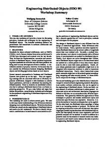
Thus these questions of endochrony and isochrony are central to our approach and make it attractive. How endochrony is feasible is intuitively illustrated in the fig-
ure 8, which shows the graph associated with the statement: �Guardhb; ui�, defined in section 4. The diagram on the left depicts the history or trace of this statement, showing the successive instants or reactions separated by thick dashed lines. Pins have been erased when performing concatenation. In the diagram on the right, an instant has been twisted and thick dashed lines have been removed, i.e., the notion of a reaction or instant has been lost. However, no information has been lost : we know that u should be got exactly when port b holds the value true, and thus it is only needed to wait for b in order to know whether u is to be waited for also. This suggest the way endochrony is formally defined (see [19]). An object O considered with a given environment O0 is isochronous if and only if object O has the same reactions (in terms of presence/absence of ports, disregarding values of ports) whether it is considered on its own or placed in the environment (OkO0 ).
as Guard or Sync, figures 12 and 13) which can be defined in B DL with the only help of class Cell. The class Cell (defined figure 10) is a generic class of two parameters (the first one, T, is a data-type and the second one , V, is a value of that data-type). Class Cell acts like a memory in which values ranging over data-type T can be stored (using port set) and retrieved (using port get). Value are transported from a transition to another by resourcing to pins. Parameter V is the initial value of the memory m. T:Type, V:val T Cell get,set:T
behaviour
u:T
get
get
m(u)
Thanks to the mathematical framework introduced in sections 3.1 and 3.2, we can give a graphical denotation of the B DL actions A (figure 3) embedded in classes and objects. The mathematical denotation [ A] of an action A is defined in the figure 9 by induction on the structure of A. To any term A recursively corresponds a graph ? whose ports � and pins � are both fx j x occurs in Ag. The function [ ] considers actions A resulting of the expansion of well-typed B DL structures S (as defined in the figure 16 of the appendix). In the figure 9, we write [ A] [�V=V ] for the substitution of V by �V in [ A] and 8W : T [ A] [W=V ] for the composition of all [ A] [W=V ] s.t. W is of type T .
X(V)
X
X(V)
X
X(V)
!A
X
A A/
= Y(W)
Y A
Y(W) A
/
Y = A
= ! A
=
A
A A/
/
u,v:T
u:T
set
m(u) get(u)
get(u)
set
m(u) set(v)
set(u)
m(v) get
X
m:T(V)
m(u)
3.5. Meaning of B DL
X(V) =
initially
get
m(u) set
set
Figure 10. The pervasive class Cell
A typical usage of class Cell is given in figure 11. The class Counter (on the left in the figure) emits on the port count the number of tick messages it receives (a trace of the counter, consisting of the concatenation 0 � 1 � 2 , is depicted on the right in the figure). Figure 12 gives the definition of class Sync, which can be used to enforce sequentiality between occurrences of groups of ports or objects. Counter tick:unit
count:int
C Cell Succ Send u:int ! tick
C.m(0)
tick
tick
count(1)
count(2)
C.get(0)
C.get(1)
C.set(1)
C.set(2)
C.m(1)
C.m(2)
...
! count(u)
Figure 11. Using Cell to define a Counter
A
=
A [*V/V]
A
=
A
V:T
V:T
W:T A [W/V]
A] of an action A
Figure 9. Denotation [
AbsSync
4. Using B DL The complete definition of the B DL language consists of the core B DL syntax of section 2 enriched with a predefined class (Cell, figure 10) and a set of pervasive classes (such
begin:unit end:unit
Sync begin,end:unit
Schedule:
S Cell
A: Sync
Send Send ! begin end !
a,b:unit
A.begin a
b A.end
Figure 12. Using Cell to define Sync
A few other pervasive, generic, classes are detailed in figure 13. The class Guard allows to condition the activation of a message Y by a boolean port X. The class Send models the synchronous transmission of a value V from a port X to a port Y. The interfaces And and Plus show that operations on booleans or integers ports X, Y, Z can be regarded as generic classes. A more significant example of B DL specification is detailed in figure 20 of the appendix. This example is self-contained and self-explanatory.
Guard X:bool,Y:unit ! X(true) ! Y
X,Y,Z:bool
And
X,Y,Z:int
Plus Send T:type X,Y:T ! X(false)
V:T
! X(V)
! Y(V)
Figure 13. Other B DL pervasives
5. Prospective Applications of B DL The use of B DL integrates naturally in an U ML objectoriented development process (figure 1). It allows to define a logical interaction model between the components described in the functional architecture of a system, with the help of a preliminary U ML design and elementary scenari. B DL descriptions can be added to the preliminary U ML design by means of stereotypes [2] in order to enrich the model with a behavioural view of the system. At this stage of the development, object-oriented methodologies such as O MT or U ML usually recommend the refinement of declarative diagram descriptions (architecture, scenari) using imperative automata specifications for describing the behavior of system components (e.g. using S DL [20], S TATECHARTS [10] or [5]1 ). All these approaches offer means of directly describing an �heterogeneous� architecture (i.e. an asynchronous network of synchronous, imperative, objects). According to the above respects, our approach radically differs from previous works [20, 10, 5]. It is motivated by the fact that stepping from a declarative description of scenari to an imperative description of behaviours is difficult without making minimal hypothesis on the actual distribution of system components and on an interpretation of communications (in the scenari) and of concurrency (in the architecture). B DL solves this key issue by implementing a declarative description of objects interaction in terms of graph families without making any assumption about their 1 which, to our late knowledge, happens to be also named B DL
distribution. This approach allows an homogeneous description of the functional architecture of distributed objectoriented applications. Mapping this architecture to a particular, heterogeneous, configuration is regarded as a separate issue of �deployment�. Given the configuration and dimensions of a target system (by means of an U ML deployment of B DL diagrams), the functional architecture of the application can be instantiated to form an assembly which defines the behaviour of the target system in terms of a distribution of reactive objects. To each object corresponds a family of graphs which can be executed by iteratively choosing composable and concatenable graphs, as defined section 3. The causal relations between the components of the target system can be interpreted in several ways: synchronous communication (within a confined target object), asynchronous communication (between distributed target objects), data or control dependencies, real-time dependencies, etc. The interpretation of distributed objects as communicating automata or symbolic transition systems allows to use efficient verification tools, such as C ADP [8], in order to verify the global safety properties of the target systems (e.g., deadlock freedom, reachability of states). The interpretation of confined objects as synchronous programs allows to compile them separately in order to generate either simulation programs or intelligent program stubs implementing the scheduling of communications and concurrency of an object with its remote environment. Just as I DL specifications describe what application components exchange with its environment, B DL specifications describe how these components interact with it. A B DL specification allows to compile its interaction pattern (i.e. communication and concurrency) as well as an I DL specification allows the automated generation of program stubs for an application component (i.e. code for marshaling and exchanging data with the environment and for plugging it with common O RB communication resources). Thanks to its formulation using a partial-order theoretical framework, the B DL specification of a capsule (a set of application components, embedded according to a given configuration) allows an optimized compilation by resourcing to code generation techniques employed in synchronous programming languages, such as S IGNAL [6], for implementing embedded systems. More precisely, the graph family ? of a B DL-capsule can be translated into a S TS scheduling specification (Symbolic Transition Systems, [4, 16]) which describes both the control model (e.g. the valuations) and the causality model (e.g. the arrows) of the service. By determining the tasks in this graph (i.e. the control configurations or states) and by hierarchizing them (i.e. determining the logical relations between them), the program implementing each capsule of a B DL specification can be automatically generated.
6. Conclusion We have introduced the formal definition of a declarative specification language for describing distributed reactive objects, B DL, and demonstrated that B DL provides a unified medium for specifying, verifying and compiling distributed real-time applications. In contrast to the objectoriented extensions of conventional automata-based tools for specifying distributed systems [20, 10, 5], the B DL language implements a smoother phase transition between the specification of a system and its configuration. This allow to feature a better integration into U ML. B DL supports a description of object components interaction which respects both the functional architecture of U ML system designs and the declarative style of U ML diagram descriptions. B DL implements a both simple and expressive theoretical framework which allows to specify both the causality and the control models of object interactions independently of any hypothesis on the actual configuration of the system. The definition of B DL offers new perspectives for a flexible verification of systems, the generation of optimized code, an accurate validation of applications by supporting the manipulation of both causal and control dependencies. B DL aims at maximizing the re-usability of high-level specifications and at minimizing programming and validation efforts for the implementation of real-time, object-oriented, distributed systems.
References [1] R. Alur, G.J. Holzmann and D. Peled. A analyzer for Message Sequence Charts. In Tools and Algorithms for the Construction and Analysis of Systems. Lecture Notes in Computer Science v. 1055., p. 35–48. Springer, 1996. [2] S.W. Ambler. The Unified modeling language and beyond: the techniques of object-oriented modeling, (http://www.ambysoft.com), August 1997. [3] C. Andr´e, F. Boulanger, M.-A. P´eraldi, J.-P. Rigault, and G. Vidal-Naquet. Objects and synchronous programming. In European Journal on Automated Systems, v. 31(3), p. 417–432. Hermes, 1997. [4] A. Benveniste, P. Le Guernic and P. Aubry. Compositionality in dataflow synchronous languages: specification and code generation. In Malente Workshop on Compositionality. W.P. de Roever, A. Pnueli Eds, 1997. [5] F. Bertrand and M. Augeraud. B DL, a language to control the behavior of concurrent objects. In Conference on Domain-Specific Languages, p. 133-144. U SENIX, 1997. [6] A. Benveniste, P. Le Guernic and C. Jacquemot. Synchronous programming with events and relations: the S IGNAL language and its semantics. In Science of Computer Programming, v. 16, 1991.
[7] R. Breu, U. Hinkel, C. Hofmann, C. Klein, B. Paech, B. Rumpe and V. Thurner. Towards a formalization of the unified modeling language. In Proceedings of the 11th European Conference on Object-oriented programming. Lecture Notes in Computer Science v. 1241. Springer, 1997. [8] J.-C. Fernandez, H. Garavel, A. Kerbrat, L. Mounier, R. Mateescu and M. Sighineanu. Computer Aided Verification. In CADP: a protocol validation and verification toolbox, 1996. [9] J. Grabowski, E. Rudolph and P. Graubman. Message Sequence Charts: composition techniques versus OOtechniques. In Proceedings of the 7th. S DL forum, 1995. [10] D. Harel and E. Gery. Executable Object Modeling with Statecharts. In Proceedings of the International Conference on Software Engineering, p. 246-257. I EEE, 1996. [11] I. Jacobson, M. Christerson, P. Jonsson and G. Overgaard. Object-Oriented Software Engineering – A Use Case Driven Approach. ACM, 1992. [12] C. Jard, J.-M. J´ez´equel and L. Nedelka. An Approach to Integrate Formal Validation in an OO Life-cycle of Protocols. In Proceedings of F MOODS ’96. Chapman & Hall, March 1996. [13] L. Lamport. Specifying concurrent program modules. In ACM Transactions on Programming Languages and Systems, v. 5(2), p. 190-222. ACM, 1983. [14] S. Pickin, C. Sanchez, J.-C. Yelmo, J.-J. Gil and E. Rodriguez. Introducing formal notations in the development of object-based distributed applications. In Proceedings of F MOODS ’96, p. 87–102. Chapman & Hall, March 1996. [15] A. Prinz. Including behaviour into interfaces. In Proceedings of F MOODS ’96, p. 37–49. Chapman & Hall, March 1996. [16] A. Pnueli, et al. Symbolic Transition Systems. In Malente Workshop on Compositionality. W.P. de Roever, A. Pnueli Eds. September 1997. [17] J. Rumbaugh, I. Jacobson and G. Booch. Unified Modeling Language Reference Manual. I SBN n. 0-20130998-X. Addison-Wesley, 1997. [18] B. Selic, G. Gullekson and P. T. Ward. Real-Time Object-Oriented Modeling. John Wiley & Sons, 1994. [19] J.-P. Talpin, A. Benveniste, C. Jard, B. Caillaud, Z. Bouziane and H. Canon. BDL, a specification language for distributed object-oriented real-time systems. Technical Report n. 1145. I RISA, 1998. [20] Recommendation Z.100 - CCITT specification and description language (S DL). International Telecommunication Union, March 1993.
Appendix We formally define well-typed B DL phrases by the relation E ` S : t (figure 16) which associates a structure S to its type or signature t (figure 14) given an environment E . An environment E is a finite relation between identifiers I and types t (i.e. E 3 (I : t)). A type is either a data-type d or an object type t. The relation E ` S : t is defined by induction on the syntax of B DL (figures 2 and 3). Each rule in the definition has the form P1C::n and defines the relation C as the conclusion of the conjunction of smaller premises P1 to Pn . Each rule is universally quantified over all its meta-names.
d ::= bool j int j union V1::n t ::= type d j port d j val d j class E j (I : t):t0 j [V : d]:t Figure 14. Data-types
d and object-types t
The relation E ` S : t implements a contra-variant subtyping relation t � t0 between objects (figure 15). We identify the types (I : t):t0 and (J : t):(t0 [I=J ]) for all J not occurring in t; t0 . port d � port d
val d � val d
E � E0 t � t0 E � E 0 0 0 E; (I : t) � E ; (I : t ) class E � class E 0 t0 � t000 t00 � t t � t0 0 00 000 (I : t):t � (I : t ):t [V : d]:t � [V : d]:t0 t t0
Figure 15. Sub-typing relation �
The relation of well-typing E ` S : t is structurally decomposed into a relation E ` D : t on declarations D, a relation E ` I : t on identifiers and a relation E ` A on actions A. Notice that the type associated with a structure S is exactly its �interface�. Also notice that declaring this interface (i.e. �class C : C 0 is D�) prevents other identifiers (i.e. in D but not in C 0 ) to be visible from the environment. Similarly, every declaration D introduces a binding between an identifier and a structure. Therefore, the relation E ` D : t also associates declarations D to object types. The type-checking of the selection of an element in a compound class or in an array class is implemented by the relation E ` I : t between compound identifiers I and types t as follows. Finally, the type-checking relation between environment E and actions A checks the conformance between datatypes and object-types already declared and visible (in E ) and the way they are used (in A).
E ` C :t E ` object O of C : class (O : t) E ` D :t E ` class C is D : class (C : t) E ` D : t E ` C 0 : t0 t � t 0 E ` class C : C 0 is D : class (C : t0 ) E ` T : type d E; (V : val d) ` D : t E ` class C [V : T ] is D : class (C :[V : d]:t) E ` T : t E; (I : t) ` D : t0 E ` class C (I : T ) is D : class (C :(I : t):t0 ) E ` S :t (E; E1::i?1 ` Di : class Ei )i=1::n E ` D1::n : class E1::n E ` T : type d E ` port X : T : class (X : port d) E ` C :(J : t0 ):t E ` I : t00 t0 � t00 E ` C hI i : t[J=I ] Figure 16. Relation
Figure 17. Relation
E ` D :t
E; (I : t) ` I : t E ` C :(V : d):t E ` W : val d E ` C [W ]: t[W=V ] E ` I : class (E 0 ; (J : t)) E ` I:J : t E ` I :t E ` X : port d E ` V : val d E ` X (V ) E ` X (V ); Y (W ) E ` X (V ) ! Y (W ) E`A E ` A; A0 E ` A; A0 E `!A E ` A or A0 E ` A k A0 E ` T : type d E; (V : val d) ` A E ` all V : T A E ` T : type d E; (V : val d) ` A E ` any V : T A Figure 18. Relation
Figure 19. Relation
E`A
Salesperson
type C , S; type ’a Opt = none | some of ’a; type Status = free | busy;
Salespeople sp
s:S Class Salesperson inherits class Human. A new port is declared (sell) and synchronized with port work.
! work work
Figure 20. B DL specification of the salesdepartment
type S = sleeping | working
Class Salespeople is made of a collection of Salesperson, indexed by type S.
sell
s Cell
!
!
n[s].get(free)
cr[c].wakeup
sp[s].wakeup
m[c].set(some s)
n[s].set(busy)
s.get(working)
s.get(working)
Customers cr
work
sleep ! work s.set(sleeping) !
Class Human defines the generic behaviour of Customer and Salesperson: It is made of an instance of class Cell. Three possible behaviours are defined: - transition from sleeping state to working state, - asserting activity by emitting the port work, - transition from working state to sleeping state.
Cell get : X
buy
Class Switchboard is used to keep track of the (Customer,Salesperson) relation. It is made of: - a collection of Cells of type S Opt, indexed by type C and initialized to none, - a collection of Cells of type Status, indexed by type S and initialized to free.
X:Type,x0:X
set : X
!
c:C
buy
s.set(working)
m[c].get(none)
! Customer
wakeup
!
sleep !
s.get(sleeping)
Salesdepartment c:C
sell
Human wakeup
s:S
m[c].get(some s)
n[s].get(busy)
cr[c].buy
sp[s].sell
! m[c].get(some s)
n[s].get(busy)
cr[c].sleep
sp[s].sleep
m[c].set(none)
n[s].set(free)
Switchboard c:C m c:C n
Class Salesdepartment is made of and synchronizes classes Salespeople, Customers and Switchboard. The behaviour of this class is the parallel composition for all customers (c in type C), of a choice among salespeople (s in type S) of three possible behaviours: - Provided customer cr[c] is not connected and salesperson sp[s] is free, ports wakeup may occur both on cr[c] and on sp[s], in which case the relation (c,s) is recorded in the switchboard. - Provided cr[c] is connected to sp[s], port buy may happen on cr[c] if and only if port sell happens on sp[s]. - Provided cr[c] is connected to sp[s], ports cr[c].sleep and sp[s].sleep may happen synchronously, in which case the relation (c,s) is discarded from the switchboard. This class holds a high degree of parallelism since all customers and salespeople can be active during the same reaction.