Beam based Alignment of the LHC Transfer Line Collimators. At LHC injection energy the aperture available in the transfer lines and in the LHC is small and the.
EUROPEAN ORGANIZATION FOR NUCLEAR RESEARCH European Laboratory for Particle Physics
Large Hadron Collider Project
LHC Project Report 852
Beam based Alignment of the LHC Transfer Line Collimators H. Burkhardt, B.Goddard, V. Kain, S. Redaelli CERN, Geneva, Switzerland
Abstract At LHC injection energy the aperture available in the transfer lines and in the LHC is small and the intensities of the injected beams are an order of magnitude above the damage level. The setting of protection elements such as the transfer line collimators is therefore very critical; mechanical and optical tolerances must be taken into account to define the nominal setting. Being able to measure and control the collinearity of the collimator jaws with the beam relaxes the requirement on the settings considerably. A method to measure angular misalignment of the collimator jaws in the transfer line based on a transmission measurement is discussed. Simulations have been made and a test of principle has been carried out during the 2004 commissioning of the transfer line TI 8.
Presented at PAC 2005, Knoxville, USA, May 16-20, 2005 CERN, CH-1211 Geneva 23, Switzerland Geneva, June 2005
Beam based Alignment of the LHC Transfer Line Collimators V. Kain, H. Burkhardt, B. Goddard, S. Redaelli, CERN, Geneva, Switzerland Abstract At LHC injection energy the aperture available in the transfer lines and in the LHC is small and the intensities of the injected beams are an order of magnitude above the damage level. The setting of protection elements such as the transfer line collimators is therefore very critical; mechanical and optical tolerances must be taken into account to define the nominal setting. Being able to measure and control the collinearity of the collimator jaws with the beam relaxes the requirement on the settings considerably. A method to measure angular misalignment of the collimator jaws in the transfer line based on a transmission measurement is discussed. Simulations have been made and a test of principle has been carried out during the 2004 commissioning of the transfer line TI 8.
BEAM
a
motor steps
b INTRODUCTION The LHC beams will be injected from the SPS via the two transfer lines TI 2 and TI 8. The momentum of the proton beams after the acceleration in the SPS is 450 GeV/c and a full nominal batch extracted from the SPS consists of ��½¿ protons, which is more than one order of about magnitude above the assumed damage level. The available aperture in the LHC at injection energy is 7.5 � [1], and can be even tighter in the transfer lines [2]. Key components of the protection of the LHC aperture against transfer failures are the transfer line collimators TCDI (Target Collimator Dump Injection). The required setting of the 1.2 m long graphite TCDI collimator jaws is 4.5 � from the beam axis, and accurate setting is crucial to cope with the small tolerances at injection. Adjusting the collinearity of a collimator jaw with the beam could contribute greatly to the achievable alignment accuracy, as the mechanical angular misalignment is up to 350 �m, with typical beam sizes of 500 �m. Each collimator jaw is hence equipped with two motors. The alignment of the TCDI will be fairly time-consuming, and will only be done occasionally e.g. after shut-down periods. This paper presents a beam-based alignment method to improve collinearity between beam and jaw for pulsed beam lines such as the LHC transfer lines. The results of simulations and a proof-of-principle test of the method during the beam commissioning of the transfer line TI 8 in 2004 are shown.
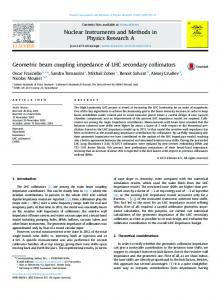
Figure 1: An illustration of the alignment scan. Both jaw ends are moved by the same amount of steps in opposite directions. (BLMs), the signals of beam current transformers (BCTs) and BLMs far downstream are used. A prerequisite for the procedure is an accurate knowledge of the beam trajectory at the collimator location, which is normally obtained via interpolation between measurements of two nearby beam position monitors. Each jaw is aligned individually. The edge of the jaw is closed to the beam axis, where ideally it scrapes half of the beam intensity. BCTs up- and down-stream are used to measure the beam transmission. One complication is that the short low-Z jaw material (1.2 m graphite jaw) is not a perfect absorber: it acts partly as diluter, such that for ideal alignment the expected beam transmission is slightly greater than 50%. The method relies on the fact that any angular misalignment results in a reduced transmission with respect to the maximum achievable value. The two ends of the jaw can be moved individually, since each jaw is equipped with two stepping motors. The collinear alignment is optimised by varying the angle while keeping the average position the same, using both motors, and hence producing a scan of transmission versus difference between the steps of motor 1 and motor 2, Fig. 1.
SIMULATED MEASUREMENT TRANSMISSION MEASUREMENT FOR COLLIMATOR JAW ALIGNMENT The proposed alignment procedure is based on a transmission measurement; instead of local beam loss monitors
The proposed method was tested in a simulation including realistic parameters and tolerances. The beam impacting the collimator jaw is not completely absorbed. It is attenuated depending on the length of tra-
0.53
30
Interpolated position at TCS is -1.8mm +/- 0.27mm
0.52 25
0.51
transmission
0.5
BPKH4004 = -2.11mm = 0.25mm
20
0.49
BPKH4003 = -1.26mm = 0.15mm
15
0.48 0.47
10
0.46 5
0.45 0.44
0 0
0.43
-3 -2.9 -2.7 -2.6 -2.5 -2.4 -2.3 -2.2 -2.1 -2 -1.9 -1.8 -1.7 -1.6 -1.5 -1.4 -1.3 -1.2 -1.1 -1 -0.9 beam position [mm]
0.42 -0.0003
-0.0002
-0.0001
0
1e-04
0.0002
0.0003
(a-b) [m]
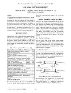
Figure 2: Simulated result of alignment scan. The maximum of the curve corresponds to the maximum achievable collinearity between beam and jaw. versed matter. The attenuation is calculated according to ��������, where l is the traversed length and L the interaction length of the material (for the TCDI graphite jaws L � 40 cm). If the jaw is not collinear to the beam axis, part of the beam will not traverse the whole length of the collimator, and the attenuation will depend on the misalignment angle. Hence the calculation of the transmission of the impacting beam is done in practice for small transverse slices of the jaw. Particles which traverse the collimator jaw will generally have an increased divergence from scattering processes, resulting in larger Courant-Snyder invariants. The effect of multiple Coulomb scattering [4] is included by convoluting the particle distributions with the probability densities for the different scattering processes. It is assumed that only particles with a normalized Courant-Snyder invariant smaller than a certain cut-off parameter (assumed to be 8 � ) survive, the rest are lost on the aperture. The simulation result in Fig. 2 shows the outcome of a transmission scan for an initially perfectly aligned jaw, with a and b as shown in Fig. 1. From this curve it appears that an alignment accuracy (a-b) of better than 100 �m should be possible with such a scan. The jaw is properly aligned for the motor settings which correspond to the maximum in the u-shape curve of Fig. 2.
TEST OF THE METHOD DURING TI 8 BEAM COMMISSIONING The proposed method was tested during three hours of the TI 8 commissioning which took place in 2004 [5]. The goal of this first test of the alignment method was a qualitative check of the method. An LHC horizontal secondary collimator (TCS) was installed in TT40 for a robustness test of its jaw material with LHC beam extracted from the SPS. The transfer line collimator design is based on the TCS design (1 m C-C jaws) [6]. This collimator was used with low intensity beam
Figure 3: The results of the BPM measurements to define the beam position at the collimator.
��½¼ protons) to investigate whether the effect of an( gular misalignment was clearly visible with the limited resolution of a transmission measurement. The beam position at the collimator location was �� � mm � � �� mm, obtained with the interpolation between two BPMs in TT40. The results for the beam position are shown in Fig. 3. Fig. 4 shows transmission versus time as ratio between intensity at the BCT at the end of the line and the BCT in the SPS. The parts of the graph in red mark the areas where one collimator jaw was moved in. During period 1 the jaw was moved to the interpolated beam position with the assumed motor calibration and kept at the same position for 30 minutes. (The data from this period was used to define the beam stability at the collimator location [7].) From the transmission (only � � rather than � � ) it is clear that either the alignment of the jaw or the calibration of the motor steps was not perfect. During period 2 the same jaw was moved back to the interpolated beam position. Since the transmission was still only about 30%, the jaw was retracted by 0.5 nominal � (1 real � with the small emittance beam used for the test), corresponding to measurement point b1. This position change, of 300 �m, is clearly visible in the transmission, Fig. 4. The effect on the transmitted intensity indicates that it should be possible to align the jaws to better than � ��m with this method. For measurement points b2 and b3, a single jaw end was moved further into the beam by 2 � (corresponding to 1 nominal � ), while the other jaw end stayed at the setting of b1. The effect on the transmission was even more obvious. Due to the limited measurement time a full scan could not be done; however, even with this short test it was clear that the collimator jaw was not perfectly aligned with the beam. For an initially well aligned jaw, measurement point b1 would have given the maximum transmission. The maximum lies between the motor settings of b1 and b3. During b2 the jaw was even more misaligned. Each measurement point was obtained with about 20 shots (about 6 minutes per measurement point). A full scan with about 10 measurement points per jaw would take two
1.1 1
second jaw in
transmission ITI8/ISPS
0.9
jaws out
0.8
first jaw in + tilt variation
jaws out
0.7
➁
0.6
b1
first jaw in
0.5
➀
0.4
b3
b2
0.3
b0
0.2 0.1 11:00 pm 11:25 pm 11:50 pm 12:15 am 12:40 am
1:05 am
1:30 am
1:55 am
Figure 4: Transmission during the test period.
Beam Loss Monitors for Transmission Measurement
1.1
20
b1
b2
18
b3
1
16 9 +
1.2
Figure 5: BLM and BCT signals during scraping with the collimator.
CONCLUSION
REFERENCES
A method for aligning collimator jaws in pulsed beam lines such as the SPS to LHC transfer lines has been presented. The measurement of the transmitted intensity rather than local beam loss serves as alignment criterion. The method has been simulated numerically, where an alignment precision of about 100 �m was obtained. The method has also been tested experimentally, where the first tests with beam during the TI 8 commissioning showed a clearly visible change of the transmitted intensity for a 300 �m change of the angular misalignment with a low intensity beam. The beam tests demonstrated that alignment below 150 �m (corresponding to angle of 150 �rad for a TCS jaw) accuracy can be reached with this technique. Signals of beam loss monitors far downstream from the collimator location can be used as complimentary feedback during the alignment procedure.
BLM response
Fig. 5 shows the intensity signal at the BCT at the end of the line and also a loss signal for a BLM 700 m downstream from the collimator location during period 2. The two signals show an anti-correlation and either signal could serve as basis for the alignment. The collinear motor setting would correspond to the minimum of the curve BLM signal versus difference between steps of motor 1 and motor 2. The BLM signal seems less noisy than the BCT signal, which would clearly be an advantage, and BLMs far downstream of the collimator jaw could give complimentary information in the case of alignment with low resolution BCTs or the intensity reading of BPMs.
14 0.9 12 0.8 10 0.7
8
0.6
0.5
BCT measurement [10 p ]
hours per collimator.
6 BLM signal BCT measurment 1:12 am
1:20 am
4 1:28 am
1:36 am
1:44 am
1:52 am
[1] S. Redaelli et al., “LHC Aperture and Commissioning of the Collimation System”, Proc. Chamonix XIV, CERN-AB2005-014, CERN, Geneva, Switzerland, 2005. [2] B. Goddard et al., “Aperture Studies of the SPS to LHC Transfer Lines”, these proceedings. [3] H.Burkhardt et al., “Collimation in the Transfer Lines to the LHC”, Proc. EPAC ’04, Lucerne, Switzerland, 2004. [4] V.Kain et al., “Attenuation and emittance growth of 450 GeV and 7 TeV proton beams in low-Z absorber elements”, Proc. EPAC 04, Lucerne, Switzerland, 2004. [5] J. Uythoven et al., “Commissioning of the LHC Transfer Line TI 8”, these proceedings. [6] A. Bertarelli et al., “The Mechanical Design for the LHC Collimators”, Proc. EPAC ’04, Lucerne, Switzerland, 2004. [7] J. Wenninger et al., “Beam Stability of the LHC Beam Transfer Line TI 8”, these proceedings.