TUPPC111
Proceedings of ICALEPCS2013, San Francisco, CA, USA
ONLINE STATUS AND SETTINGS MONITORING FOR THE LHC COLLIMATORS∗ G. Valentino† , CERN, Geneva, Switzerland and University of Malta, Msida, Malta R. W. Aßmann‡ , D. Jacquet, S. Redaelli, E. Veyrunes, CERN, Geneva, Switzerland Abstract The Large Hadron Collider is equipped with 100 movable collimators. The LHC collimator control system is responsible for the accurate synchronization of around 400 axes of motion at the microsecond level, and with the precision of a few micrometers. The status and settings of the collimators can be monitored by three displays in the CERN Control Center, each providing a different viewpoint onto the system and a different level of abstraction, such as the positions in mm or beam size units. Any errors and warnings are also displayed. In this paper, the display operation is described, as well as the interaction that occurs when an operator is required to identify and understand an error in the collimator settings.
c 2014 CC-BY-3.0 and by the respective authors Copyright ○
INTRODUCTION The Large Hadron Collider (LHC) is at the particle accelerator technology frontier, with a stored beam energy higher than any previous collider. It is protected from potential damage by several machine protection systems. The collimation system provides cleaning of halo particles before they quench the super-conducting magnets [1]. Collimators also protect the aperture from single-turn abnormal beam losses, which may occur if the beams are mis-kicked during injection or dump. A total of 86 collimators are installed in the LHC rings, 43 per beam. Fourteen collimators are also installed in the two transfer lines that transport beam from the Super Proton Synchrotron (SPS) into the LHC. Each collimator consists of two blocks (known as ‘jaws’) of carbon, copper or tungsten material which are positioned symmetrically on either side of the beam with an accuracy of 5 µm. The only exception is the TCDQ collimator in the beam dump protection region, which has a single jaw. Each of the four jaw corners can be moved individually by a dedicated stepping motor [2]. Jaw movement requests are sent by application software in the top layer to Unix/LynxOS servers, which then transmits them to the low-level Motor Drive Control (MDC) module. Linear Variable Differential Transformers (LVDTs) provide an independent measurement of these four settings, as well as the upstream and downstream jaw gaps. The measured values are transmitted back to the application software via the Position Readout Survey (PRS) module. Four resolvers count the steps of each motor, and ten switches ∗ Research
supported by EuCARD ColMat WP 8
‡ presently
at DESY, Hamburg, Germany
†
[email protected]
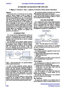
Figure 1: Schematic showing the arrangement of the collimator sensors and controllers.
are in place to prevent the jaws from moving full-in, fullout or hitting one another. A schematic of the arrangement of the sensors and controllers is provided in Fig. 1. Collimation is required at all phases (injection, ramp, squeeze and physics) due to the high stored beam energies present in the machine. The jaw position settings depend on key beam parameters, such as the energy, orbit and β-functions, which change as a function of time, energy and/or β ∗ (the value of the β-function at the interaction point (IP)). The result is unprecedented complexity, with approximately 400 axes of motion [2] requiring functionbased settings and a redundant interlocking strategy. The settings must be continuously monitored and compared to the desired values.
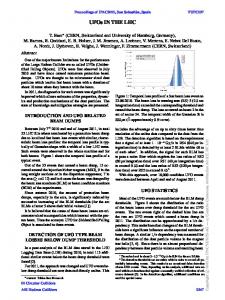
COLLIMATOR PARAMETER SPACE A schematic of the collimator settings parameter space is shown in Fig. 2. The jaw corner positions in mm (M1, M2, M3 and M4) for any point in the operational cycle are determined from the local beam-based parameters (shown in blue) and the half-gap opening in units of beam σ (shown in red) at each collimator. Mechanical parameters such as the jaw tilt angle (θcoll ) and the jaw length (Lcoll ) are shown in green. The beam-based parameters are typically measured via beam-based alignment [3] at four points: injection, flat top, after the squeeze and in collisions. Functions are generated to ensure that collimators are always at the optimal positions during dynamic changes of configuration. The settings are stored in a beam process, which also contains settings of other LHC devices for a given machine stage in
ISBN 978-3-95450-139-7 836
User Interfaces and Tools
Figure 2: Collimator settings parameter space [4].
the cycle [5]. Beam processes are then played in the appropriate order by the LHC sequencer [6]. The jaw positions are interlocked at all times by three categories of interlocks: 1. inner/outer limits for each jaw corner and gaps, stored in an actual or function beam process. 2. inner/outer β ∗ limits on the jaw gap, stored in a discrete beam process. 3. energy limits on the jaw gap, stored in a discrete beam process. Typical values for the limits are ±400 µm, or ∼1 σ. If the limits are exceeded at any time, the beam is automatically dumped. As the β ∗ and energy limits are stored in a discrete beam process, they are independent of the jaw positions and will still cause an interlock if the jaws fail to move e.g. during a ramp or squeeze [2].
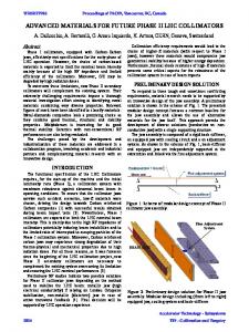
STATUS AND SETTINGS MONITORING Low-level Monitoring As is evident from Fig. 2, there are two main levels of abstraction in the collimator system settings. The lower level consists of the jaw positions in mm and the related software interlocks, whereas the higher level consists of beambased parameters which the hardware is not aware about, such as the half gap N in units of nominal σ (computed using the nominal beam emittance of ϵ = 3.5 µm), the βfunction and the beam size, which are used to calculate the settings in mm. The higher level parameters are important to understand the status of the system, such as whether the collimation hierarchy is correctly set up. The collimator statuses and jaw positions fixed display or ‘vistar’ shown in Fig. 3 is designed to monitor the system at the lower level. The vistar is displayed via two overhead monitors in the CERN Control Center, and is also available online [7]. Each screen shows the LHC ring and transfer User Interfaces and Tools
TUPPC111
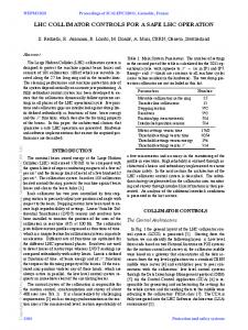
line collimators in each beam, grouped by IP and ordered by their longitudinal position in the ring. The border color coding reflects the standard convention for the beam being displayed (blue for B1, red for B2). The status of the injection protection collimators is red because the screenshot was taken with the LHC at flat top, and their jaw positions are outside the injection limits, therefore preventing injection. The left and right jaws of each collimator are represented horizontally inside a box. The average of the LVDT upstream and downstream measurement values of each jaw are calculated. Two boxes representing the jaws are placed inside the main box, and are sized such that they give an accurate impression of the gap between the jaws, which is depicted in white. The maximum retraction position that can be displayed is ±30 mm. The jaw boxes are colored according to the status of the collimator. Bracketing the jaws are the MDC and PRS status boxes, as well as the averages of the left-upstream / left-downstream and right-upstream / right-downstream LVDT values in mm. The color codes for the collimator statuses and MDC/PRS warnings and errors are available in Table 1 and Table 2 respectively. The display is used extensively by the operation crews, for example to ensure that the collimators are correctly armed before the ramp and squeeze procedures are started. The collimation system is qualified regularly by performing betatron (horizontal and vertical plane) and momentum (positive and negative offset) beam loss maps [8]. Qualification of the hierarchy is done at four stages of the machine cycle: injection, flat top, after the squeeze and during collisions. This leads to a total of 32 loss maps for both beams. The four status boxes at the bottom of the screen alert the operators to the expiry of the most recent validation for the current LHC beam mode, so that collimator settings may be qualified for the next period of operation. If more than one week is left until the deadline, the status is green. With one week or less to go, the status turns yellow, and if the validity period is expired the status turns red. The status is intended simply for informational purposes and does not affect the collimation system operation in any way. Typically, 3 months are set for the expiry of the injection, flat top and squeezed loss maps, and 1 month is set for the expiry of the physics loss maps. The loss map validity dates can be updated from a dedicated graphical user interface (GUI) application, and are stored in a table in the LHC software architecture. A more detailed view of the MDC and PRS error and warning messages is provided by the collimator controller application GUI (see screenshot in Fig. 4). The same color coding is used as in the vistar. There are a total of 19 MDC errors, 4 MDC warnings, 17 PRS errors and 5 PRS warnings which can occur for the LHC ring collimators, excluding the TCDQ and injection protection collimators. These include detection of lost motor steps, a large difference between the jaw settings and the LVDT readouts and jaw positions which exceed the limits. Hence, the overhead vistar acts as a quick diagnostic tool for the collimator expert, ISBN 978-3-95450-139-7 837
c 2014 CC-BY-3.0 and by the respective authors Copyright ○
Proceedings of ICALEPCS2013, San Francisco, CA, USA
TUPPC111
Proceedings of ICALEPCS2013, San Francisco, CA, USA
Figure 3: Collimator statuses and jaw positions B1 vistar [9].
c 2014 CC-BY-3.0 and by the respective authors Copyright ○
Table 1: Color Codes for the Collimator Statuses
Figure 4: Collimator status display with detailed error and warning messages [10].
while the exact warning or error message is viewed by hovering the cursor over the collimator name in the GUI. All the relevant errors and warnings are reported in the LHC Alarms SERvice (LASER) [11].
High-level Monitoring Parameters related to the higher level of abstraction can be viewed in the display shown in Fig. 5. These include the half gap opening in units of σ, the momentum cut made by the primary collimator in the momentum cleaning region, as well as the nominal β-functions at each collimator. Several static data, including the azimuthal angle in the transverse plane for each collimator can be viewed. A summary ISBN 978-3-95450-139-7 838
Colour
Description
Green Yellow Red Purple
WAITING COMMANDS MOTION EXECUTION UNCONFIGURED ARMED
table (see screenshot in Fig. 6), also available online [12], provides important settings information at a glance, such as the tightest half gap opening in units of σ of the primary, secondary and tertiary collimators. This display is used to confirm that the collimator settings in units of σ are correct before performing the beam loss maps, following beam-based collimator alignment. It is the only tool which provides an online view of the jaw gaps without requiring any input from the beam process settings. The tool will later be extended to include the β-functions measured during beam-based collimator alignment. User Interfaces and Tools
Proceedings of ICALEPCS2013, San Francisco, CA, USA
TUPPC111
Figure 5: Higher-level collimator settings display.
Table 2: Color Codes for the MDC/PRS Warning and Errors Colour
Description
Green Yellow Red
No PRS/MDC Warnings or Errors PRS and/or MDC Warnings PRS and/or MDC Errors
ACKNOWLEDGMENTS The authors would like to thank A. Bland for help in setting up the collimator status and jaw positions online display, as well as the LSA and database teams for their support.
REFERENCES [1] Report No. CERN-2004-003-V1, edited by O. S. Br¨uning, P. Collier, P. Lebrun, S. Myers, R. Ostojic, J. Poole, P. Proudlock. [2] S. Redaelli, R. W. Assmann, R. Losito, M. Donze, A. Masi, “LHC collimator controls for a safe LHC operation”, Proceedings of ICALEPCS’11, Grenoble, France, pp. 11041107, 2011.
Figure 6: Summary display of collimator settings.
[3] G. Valentino et al., “Semiautomatic beam-based LHC collimator alignment”, Phys. Rev. ST Accel. Beams 15, 015002 (2012). [4] S. Redaelli, R. W. Assmann, M. Jonker, M. Lamont, EDMS LHC-TCT-ES-0001 (2007).
A complex collimation system is in place at the LHC to protect it from the high energy beams at all phases of the machine cycle. The approximately 400 axes of motion require jaw position settings and limits which are different at each stage of the cycle. Online monitoring of the statuses and settings of each of the collimators is necessary to ensure that the machine runs smoothly and safely. The operation of three displays which work together to accomplish this task was reviewed, as well as the interaction that occurs with the operator in typical scenarios. Several possible improvements may be made to the existing monitoring system. Currently, the injection protection collimator statuses routinely turn red due to an energy interlock when the beams are ramped to top energy. To a non-expert, this may seem as though there is an issue which requires action. When the beams are dumped, all collimator statuses turn red until they are sent back to the injection energy settings. Although improvements have already been made to the sequencer such that errors related to these collimators are caught during the ramp-down, the current colorcoding could potentially mask underlying problems which would otherwise be visible earlier in the fill. A clearer interlock color-coding scheme can be introduced to cater for these scenarios.
[5] D. Jacquet, R. Gorbonosov, G. Kruk, P. P. Mira, “LSA - the high level application software of the LHC and its performance during the first 3 years of operation”, these proceedings. [6] R. Alemany-Fernandez, V. Baggiolini, R. Gorbonosov, D. Khasbulatov, M. Lamont, P. Le Roux, C. Roderick, “The LHC sequencer”, Proceedings of ICALEPCS’11, Grenoble, France, pp. 300-303, 2011. [7] LHC collimation vistar, available at http: //op-webtools.web.cern.ch/op-webtools/vistar/ vistars.php?usr=LHCCOLLB1. [8] B. Salvachua et al., “Cleaning performance of the LHC collimation system up to 4 TeV”, Proceedings of IPAC’13, Shanghai, China, pp. 1002-1004, 2013. [9] G. Valentino, E. Veyrunes, LHC Project Document No. LHC-OP-ES-0025 (2011). [10] G. Valentino, R. W. Assmann, S. Redaelli, N. Sammut, “LHC collimator alignment operational tool”, proceedings of ICALEPCS 2013. [11] F. Calderini, B. Pawlowski, N. Stapley, M. W. Tyrrell, “Moving towards a common alarm service for the LHC area”, Proceedings of ICALEPCS’03, Gyeongju, Korea, pp. 580-582, 2003. [12] LHC collimation summary table, available at http://op-webtools.web.cern.ch/op-webtools/ vistar/vistars.php?usr=LHCCOLLI.
ISBN 978-3-95450-139-7 User Interfaces and Tools
839
c 2014 CC-BY-3.0 and by the respective authors Copyright ○
SUMMARY AND OUTLOOK