Bearing Fault Monitoring Using CWT Based Vibration ... - Science Direct
Recommend Documents
Jun 16, 2014 - improve the robustness of the classifier evaluation, a two-fold cross validation scheme is adopted and the order of feature samples is randomly ...
Jun 16, 2014 - Keywords: fault classification; rolling element bearing; .... Based on the DE optimization algorithm and EAM classifier, a vibration sensor-based ...
Feature ranking methods such as Chisquare, ReliefF method are used to select ..... P. Reutemann. and I.H.Witten, The WEKA data mining software: An Update, ...
Nov 17, 2016 - Sheraz Ali Khan and Jong-Myon Kim. School of Electrical ...... 176â199, 2013. [28] M. Pineda-Sanchez, J. Perez-Cruz, J. Roger-Folch, M. Riera-.
AbstractâAs a commonly used assembly in computer cooling systems, the normal operation of a cooling fan is critical for guaranteeing system stability and ...
Available online at www.sciencedirect.com. XXI International ... bearings, gears, belts, excitation of hydraulic and aerodynamic forces, vibration caused by electrical problem etc. .... that extent, the signal detected in the metal-to-metal contact.
Scott D. Moss a, ... E-mail address: [email protected] ..... [7] D. Briand, E. Yeatman, S. Roundy, Micro Energy Harvesting, John Wiley & Sons, ...
of primary interest for structural vibration monitoring. The purpose of the paper is ...... IEEE Signal Processing Magazine, 15(1), 39}55. Prevosto, M., Olagnon, M., ...
of new sensing techniques, and on the other hand on the development of advanced ... At this point the frequencies are evaluated by Spike Energy and Shock pulse ... by the EDM machine and some are dipped in the acid solution for creating the ... of fa
Bengal Engineering and Science University, Shibpur, Howrah, India. AbstractâThe paper proposes a Rough-Set CWT based algorithm for multi-class fault ...
(MCSA) using spectral analysis and wavelet transform. .... with the defect features are chosen for the Hilbert spectrum .... The spectral kurtosis: a useful tool for.
taneously across domains based on maximum mean discrepancy(MMD) .... diagnosis model is built by using nearest-neighbor(NN) classifier in training do- main, and ... adaptation in our work is unsupervised and training domain Xtr are of la-.
Jan 27, 2016 - on lifting wavelet packet transform (LWPT), sample entropy (SampEn), and classifier ensemble. Bearing .... to extract nonlinear features for bearing fault diagnosis. With the ... present study investigates the joint use of LWPT and Sam
of the state-of-art of condition monitoring and fault diagnosis techniques has been carried out. ... condition monitoring solutions for wind turbine gearbox pre-.
the Electric Power Research Institute, the most common failure mode of an induction ... Engineering, National Institute of Technology, Hamirpur-177005, India (e-.
Email: [email protected]. R. J. Batista. Espırito Santo Exploration and Production Business Unit. Automation, Inspection and Maintenance Engineering.
Markus ¨Ozbek â Dieter Schramm ââ Dirk Söffker â. â Chair of Dynamics and Control,. University of Duisburg-Essen, Lotharstrasse 1,. 470 57 Duisburg ...
The Chisquare test is generally used in statistics to check the .... [6] P.K. Kankar, S.C. Sharma and S.P. Harsha, Rolling element bearing fault diagnosis using ... [10] V. Vakharia, V.K Gupta and P.K. Kankar, A comparison of feature ranking ...
Jun 21, 2018 - Some indicators, such as kurtosis, maximum correlated ..... shows the envelope spectrum of the optimal notch filter signal, some apparent ...
were performed on a bevel gearbox test rig using vibration measurements obtained ... gear tooth due the difficulty in choosing an appropriate window length to ...
Aug 9, 1994 - On the other hand, active vibration isolation systems, with .... When the displacement, velocity, acceleration and jerk of the mass are used for.
Peer-review under responsibility of the scientific committee of Eurosensors 2014 ... bSchool of Mathematical Science, University College Cork, Cork, Ireland .... This work is financially supported by Science Foundation Ireland (SFI) Principal ...
Wind turbine towers play an important role in supporting the energyYgenerating components such as blades, hubs, and nacelles and in resisting wind loads ...
On-line vibration monitoring of bearing faults in induction machine using ... monitoring and diagnosis of huge rotating machines. Different ... electrical machines.
Bearing Fault Monitoring Using CWT Based Vibration ... - Science Direct
1. Introduction Bearings are widely used in various types of machines ranging from simple induction electric motor to complex manufacturing facilities. Bearing faults, in fact, are a common cause of machinery failures. Rotating machine is a common class of machinery in the industry. The root cause of machinery faults in rotating machinery is faulty rolling element bearing .There are many bearing fault diagnosis techniques available but still the methods that are more effective need to be researched and developed for accurate detection of the fault before machine failure. Several methods have been proposed in the literature for bearing fault detection. To inspect raw vibration signals, a wide variety of techniques have been introduced that mainly includes classical signal processing techniques and intelligent systems. However, an effective bearing fault diagnostic technique is critically needed for a wide array of industries for
early detection of bearing defects so as to prevent machinery performance degradation and malfunction.With the emergence of new mathematical tools and AI techniques along with progress in signal processing techniques, there is ample opportunity to investigate to meet the precise requirement of bearing fault diagnosis. In this work, an experimental setup is prepared for generating vibration signals for various types of bearing faults. Then, CWT is applied to these vibration signals and a novel algorithm is developed for generating signatures of different types of bearing faults [1]. Nomenclature
W s t
time translation dilation (scale) time
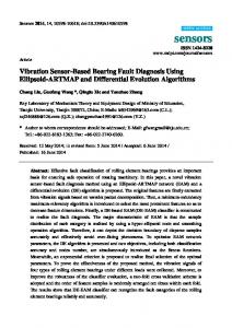
2. Experimental Setup The experimental setup used in this experiment consists of 0.25horse power induction motor, having fixed 1440 RPM, an extended shaft is mounted on the main shaft of the motor so that the seeded fault bearings can be mounted on the shaft for taking vibration data. In this experimental setup ADXL 335 accelerometer is used to capture the vibration data from bearing housing, the faulty bearings are mounted on the shaft and they are covered by the bearing housing and accelerometer is mounted on the top of the housing. In order to collect data from the accelerometer it is coupled with ARDUINO UNO board (microcontroller) which is compatible to MATLAB 2013R where the data can be captured. The Figure 1 shows schematic diagram of the experimental setup and Figure 2 shows actual experimental setup. a
b
Figure. 1(a) Schematic Diagram for Experimental setup
(b) Actual Experimental setup Equations
2.1. Accelerometer An accelerometer is a device that measures proper acceleration ("g-force"). Proper acceleration is not the same as coordinate acceleration (rate of change of velocity). Accelerometers have multiple applications in industry and science. Highly sensitive accelerometers are components of inertial navigation systems for aircraft and missiles.. Figure 3 shows ADXL 335 accelerometer which is used in the experiment.
2.2. Arduino Board Arduino is an open-source computer hardware and software company, project and user community that designs and manufactures kits for building digital devices and interactive objects that can sense and control the physical world.An Arduino board consists of an Atmel 8-bit AVR microcontroller with complementary components. Figure 4 shows ARDUINO UNO board used in the experiment.
Figure. 3 Arduino Board
2.3. Bearings Thirty seven unassembled bearings of bearing no. 6204 are arranged and on those bearings various types of faults are seeded by the EDM machine and some are dipped in the acid solution for creating the rusting effect on the races, ball and cage. Indentation is made in inner and outer race of the bearing for simulating the bearing inner and outer race defect due to overloading. In ball and cage corrosion, pitting is main cause for their failure so similar type of faults is seeded in cage and ball. Then these unassembled bearings are riveted and converted into the full assembled bearing, ready for the experimental. 3. Application of CWT for feature extraction from bearing faults
Three types of signal processing techniques are available for analyzing any signal / waveform namely time domain, frequency domain and time-frequency domain. Based on their comparison, as given in table 1.1, it is found appropriate to apply wavelet transform to analyze the vibration waveform of various types of bearing faults.
Table 1.1: Comparison of wavelet with RMS, Fourier, and STFT of a signal Technique
Domain
Characteristics
RMS
Time
Good time resolution. Poor frequency resolution.
Fourier
Frequency
Poor time resolution. Good frequency resolution.
STFT
Time Frequency (windowed)
Areas of time and frequency resolved together but fixed resolution.
Time Frequency
Areas of low frequency resolved well in the frequency domain but have poor time resolution. Areas of high frequency have good time resolution but poor frequency resolution.
Wavelet
From the above, it reveals that wavelet based techniques are most effective for extraction of features. The continuous wavelet transform has been applied to healthy bearing along with bearings with inner race, outer races, cage and ball faults and CWT plots are obtained, which they can do online. 3.1. Continuous Wavelet Transform The continuous wavelet transform is a time-frequency representation of signals. It is convolution of a signal x (t) with a set of functions which are generated by translations and dilations of a main function i.e. mother wavelet. Mathematically, the CWT is given by:
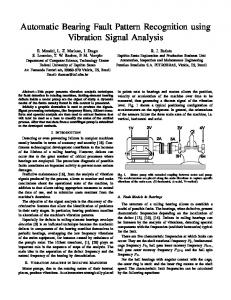
Here, τ is the time translation and s is the dilation (scale) of the wavelet and both are real numbers[2-3]. Following are the five easy steps used to compute the CWT coefficients for a signal: x Choosing a wavelet, and matching it to the section at the start of the signal. x Calculating CWT coefficients, which measures how similar the wavelet and the section of the signal are. x Shifting the wavelet to the right by translation τ, and repeating the steps 1 and 2 above. Calculating values of CWT coefficients for all translations. x Scaling the wavelet, and repeating steps 1to 3 above. x Repeating step 4 for all scales. The CWT coefficients computed as above, form a matrix at the different scale and translation values; the higher value of coefficients suggest a high correlation (similarity) between the portion of the signal and that version of the wavelet[4-6]. The colors in the plot show the relative values of the CWT coefficients. The light areas means higher values of the CWT coefficients and therefore, signal is very similar to the wavelet. Whereas, dark area means lower values of the CWT coefficients and it shows that the corresponding time and scale versions of the wavelet are dissimilar to the signal. 3.2. CWT plots of Bearing Fault : The CWT plots for waveforms of healthy bearing, faulty inner race and outer raceshave been obtained using MATLAB and are shown from Figures 4.a to Figure 6.c.
Figure. 5 Signal containing Inner Race Defects with different index of fault and its CWT plot. b
c 180
180
160
160
160
140
140
140
120
120
120
100 80
Scales
180
Scales
Scales
a
100 80
100 80
60
60
60
40
40
40
20
20
20
0
0.05
0.1
0.15
0.2
0.25
time
0
0.05
0.1
0.15
0.2
0.25
0
0.05
time
0.1
0.15
0.2
0.25
time
Figure. 6 Signal containing Outer race defect with different index of fault and its CWT plot.
4. Generation of Bearing fault Signature The proposed algorithm for generation of signatures of various bearing faults is presented through block diagram in Figure 7. Initially, CWT coefficient matrix of Bearing faults signal is obtained and subtracted from CWT coefficient
matrix of pure bearing waveform. This results in a matrix named as ‘Difference Coefficient Matrix’ (DCM), which dominantly contains the features of bearing faults data. On careful investigation of DCM, it revealed that the scalewise (i.e. row-wise) values of coefficients of DCM follow a typical pattern for a specific type of bearing faults. The elements of each row of DCM are added and the resultant matrix is named as the ‘Unique Feature Matrix’ (UFM).It is also observed that the UFM possesses unique features for a bearing faults type and it can therefore be used to generate a unique pattern/ signature[7-10].
Pure Sinusoidal Signal of healthy bearing
CWT
+
Faulty signals
Difference coefficient (DCM)
matrix
-
bearing CWT
Unique Unique pattern for the given matrix (UFM) bearing fault signature Signal
feature Scale wise sum of elements of all the rows
Figure. 7 Algorithm for generation of fault Signature
The algorithm for generating Bearing faults signature may be summarized in following five steps: Step 1: Generating data of pure as well as one of the Bearing faults waveform (both of matrix size 1x1800). Step 2: Obtaining CWT coefficient matrix (matrix size 180x1800) for both of them. Step 3: Calculating DCM(matrix size 180x1800) by subtracting CWT coefficient matrix of bearing faults waveform from CWT coefficient matrix of pure waveform. Step 4: Evaluating UFM by adding all the elements of a row of DCM (matrix size 180x1). Step 5: Plotting the row wise values of UFM with respect to its scale as signature. 5. Results and Discussion After setting up the experimental setup, CWT is applied on the raw vibration data acquired from the faulty bearings and signatures are found out for various types of faults. The CWT and signatures for various faults are shown below:
Figure. 8 (a) Inner race rusty (b) Indentation in inner race (c) Indentation of high Index
a
b 2000
c 8000
400
1500
6000
200
1000
4000 0
500
2000 -200
0 -500
0
-400 0
50
100
150
200
-2000 0
50
100
150
200
0
50
100
150
200
Figure. 9(a) Outer race rusty (b) Indentation in outer race (c) Indentation of high Index
Hence, by seeing the signatures formed by CWT one can classify the different type of a bearing fault. CWT proved to be an effective tool for identifying the faults in bearing and after training such data in Artificial Neural Network this fault diagnosis technique can be made online and fully intelligent [11-12].
6. Conclusion CWT analysis is an effective tool for analyzing bearing fault data because in this one gets all the three details i.e. time detail; frequency detail; and amplitude detail. CWT signatures are the unique feature which is shown in this paper and these can be used to classify the bearing faults visibly. We can conclude this that cwt signatures can be used as fault classification tool in ball bearing fault diagnosis. References 1. 2. 3.
4.
Manoj Gupta, Rajesh Kumar, R. A. Gupta, “A Study on Neural Network Transfer and Training Functions for Recognition of Power Quality Disturbances”, International Journal of Artificial Intelligence and Neural Networks, Vol: 2, Issue:2, pp.30-35, 2012. P.K. Kankar, Satish C. Sharma and S.P. Harsha, Fault Diagnosis of Ball Bearings Using Continuous Wavelet Transform, Applied Soft Computing, vol. 11, pp. 2300-2312, 2011. P.K. Kankar, Satish C. Sharma and S.P. Harsha, Rolling Element Bearing Fault Diagnosis using Autocorrelation and Continuous Wavelet Transform, Journal of Vibration and Control, pp.1165-1177, 2011. Sawalhi, N., “Towards simplicity in rolling element bearing localized faultsurveillance and diagnosis”, Paper submitted to the 15th IEEE Saudi Technical Exchange Meeting, King Fahd University of Petroleum & Minerals, Dhahran, Saudi Arabia, pp. 17-19, 2012.
Chen, J., Zi, Y., He, Z., & Yuan, J.. Compound faults detection of rotating machinery using improved adaptive redundant lifting multiwavelet. Mechanical Systems and Signal Processing, vol. 38, pp.36–54, 2013. 6. Gong, X., Qiao, W., & Zhou, W.). Incipient Bearing Fault Detection via Wind Generator Stator Current and Wavelet Filter, pp. 2615– 2620,2010. 7. Hong, H., & Liang, M. Fault severity assessment for rolling element bearings using the Lempel–Ziv complexity and continuous wavelet transform. Journal of Sound and Vibration, 320(1-2), pp.452–468, 2009. 8. Kulkarni, P. G., &Sahasrabudhe, A. D. . Application Of Wavelet Transform For Fault Diagnosisof Rolling Element Bearings, 2(4), pp. 138–148,2013. 9. Kumar, R., & Singh, M. Outer race defect width measurement in taper roller bearing using discrete wavelet transform of vibration signal. Measurement, 46(1), pp.537–545, 2013. 10. Muralidharan, V., &Sugumaran, V. Feature extraction using wavelets and classification through decision tree algorithm for fault diagnosis of mono-block centrifugal pump. Measurement, 46(1), pp.353–359,2013. 11. Niu, G., Widodo, A., Son, J.-D., Yang, B.-S., Hwang, D.-H., & Kang, D.-S. Decision-level fusion based on wavelet decomposition for induction motor fault diagnosis using transient current signal. Expert Systems with Applications, 35(3), pp.918–928, 2008. 12. Su, W., Wang, F., Zhu, H., Zhang, Z., &Guo, Z. Rolling element bearing faults diagnosis based on optimal Morlet wavelet filter and autocorrelation enhancement. Mechanical Systems and Signal Processing, 24(5), pp.1458–1472,2013.