... 978-3-902613-01-1. Edited by: Goro Obinata and Ashish Dutta, pp. 608, I-Tech, Vienna, Austria, June 2007. Open Access Database www.i-techonline.com ...
5 Behavior-Based Perception for Soccer Robots Floris Mantz and Pieter Jonker Delft University of Technology The Netherlands
Open Access Database www.i-techonline.com
1. Introduction The mission of this chapter is to show the possibility of boosting the performance of the vision system of autonomous perception-based robots, by implementing a behavior based software architecture with multiple independent sense-think-act loops. This research comes forth from a wider view of future robots having layered modular architectures, with higher layers controlling lower layers, in which all parts of the robots tasks (perception, behavior, motion) are behavior specific, and preferably all input-output mappings are learned. The work done in this chapter only focuses on improving the perception of robots. By implementing a behavior-based perception system of a goalie in a team of 4-legged soccer robots, we have increased its performance on localization and goal-clearing with more than 50 %. On top, we have significantly increased the performance of the image processing by making it entirely object specific, with a different color-table and set of grid-lines for each different object searched for. All improvements combined allow the robot to localize in various conditions where this was previously not possible.
2. Layered Modular Architectures Soccer playing robots as can be found in the RoboCup (www.robocup.org), are the playground to gain experience with embodied intelligence. The software architectures of those robots - that can autonomously survive in a niche of the real physical world; with limited rules necessary to survive, limited physical circumstances to account for, and simple goals to achieve (Pfeifer & Scheier, 1999) - can very well serve as an example for more complex industrial machines such as photocopiers, wafer steppers, component placement machines, CT and MRI scanners. The architecture of those machines is usually built around a single “Sense-Think-Act” loop to allow the machine to perform its task in a physical world. It is quite common that several scientific / technical disciplines, each with its own expertise, cooperate in the design. As a consequence, the most obvious basic architecture is the one as presented in Figure 1, in which for instance an image processing group solves the sense task, the control theory group solves the act task, and an AI group solves the think task. Software engineers and mechanical engineers take the responsibility over the overall software and mechanical hardware design and maintainability, respectively. Source: Vision Systems: Applications, ISBN 978-3-902613-01-1 Edited by: Goro Obinata and Ashish Dutta, pp. 608, I-Tech, Vienna, Austria, June 2007
66
Vision Systems: Applications
Artificial Intelligence Think
Image Processing
Control Engineering
Act
Sense
World
Figure 1. Architecture based on scientific / technical disciplines Usually after an initial limited architecture phase, the interfaces are quickly established and all groups retract to their own lab to locally optimize their part of the problem, thereby often making assumptions what is c.q. should be done by the other group. In the end, the data is “thrown over the wall” to the other groups, who have to cope with it. As those embedded machines increase in complexity over the years, as well as the demands from the world they operate in, the software and hardware complexity grows, and all groups start to make their sub-system versatile, robust and optimal, and hence increasingly complex for the others to use. T
Be_Striker S
A
T
T
Dribble_Ball_to_Goal
Shoot_Ball_to_Goal S
Push_Ball
Pose Goal S
A
S
A
Get Speed
T S
T S
A
Pose Self
T
A
Kick_Ball
T S
A
Pose Ball
T
S
Goto_Ball
T S
A
A
A
Set Speed
T S
A
T S
A
World
Figure 2. Layered architecture of Sense-Think-Act modules From 1991 onward it was suggested (Brooks, 1991); (Arkin, 1998); (Parker, 1996) that a different architectural concept should be followed in the sense that a layered modular
67
Behavior-Based Perception for Soccer Robots
architecture should be set-up in which higher layers control the lower layers, either by invocation actions from the lower layers or by promoting or suppressing behaviors from that lower layers. All modules run principally in parallel and on their turn invoke, promote or suppress actions of modules lower in the abstraction hierarchy. Figure 2 shows the design for a soccer robot, detailed for its role of striker. Figures 3 and 4 show the same hierarchy of figure 2, but now in more detail. Moreover, Figure 3 shows more detail on the behavior (act) part of the hierarchy, whereas Figure 4 shows more detail on the perception (sense) part of the hierarchy. Play_Game
Be_Goalie
Be_Striker
X
P1..P
Dribble_Ball_to_Goal P1..P Rrb, PHIrb
Rr,
Shoot_Ball_to_Goal
X P1..P
P1..P
Avoid_Robot
Be_Defender
Push_Ball
Rb, PHIb Vf, Vphi Vf, Vphi
P1..P
X
Goto_Ball Rb, Vf, Vphi
Wheels
Rrb, PHIrb
Kick_Ball
Vf, Vphi
Fk
Kicker
World Figure 3. Soccer playing robot in the role of striker; behavior viewpoint A striker can either dribble or shoot the ball to goal. The striker module decides on the best position (P1...P7) near the goal to dribble the ball to, from where it can successfully execute (X) a shoot to goal. Both for dribbling and shooting it needs to go to the best position behind the ball. For dribbling to goal it needs to push the ball without loosing it (avoiding others); for shooting to goal it needs to execute a kick. To perform these three behaviors it needs to perceive the pose (position and orientation) of ball and goal with respect to itself, i.e. given by vectors (R, Ø) and to set and measure the forward and angular speed of the robot (Vf,Vø). For kicking one needs to specify the kicking force (F). The pose of ball, goal and itself are measured using the vision system and the odometry (RPM of the wheels for mobile robots or steps for walking robots). Figure 4 shows that all perception modules, e.g. as to mind ones own pose, can be split into a part to discover the pose when the pose is un-known and a module to track the pose when it is well-known. To program behaviors of an autonomous system that needs to function under all circumstances in any environment, is often similar to maintaining a house of cards. Moreover, as one can not foresee as designer all possible states that the system encounter in
68
Vision Systems: Applications
its life, learning the behaviors, e.g. based on reinforcement (Sutton & Barto, 1998); (Takahashi & Asada, 2004) is a valuable solution to overcome and learn from unknown situations. However, when the dimension of input-output / state-action space becomes too high (>8) learning becomes cumbersome (Jonker et al, 2004); (Dietterich, 2000). Hence, even / especially when reinforcement learning methods are used, one should aim for layered, modular “sense-think-act” architectures in which we can learn the basic behaviors and perhaps even the perceptions. Rs, PHIs
Mind_Self
Rr, PHIr
Mind_Robot
Rbr, PHIb
Mind_Ball
Rg, PHIg
Mind_Self
Mind_Goal
Find_Percepts Vf, Vphi
Vf, Vphi
Rb, PHIb
Rg, PHIg
Rs, PHIs
X
P1..P7
Rs, PHIs
Track_Percepts Vf, Vphi
Vf, Vphi
Vf, Vphi
Vf, Vphi
Vision
Odometer
Rp, PHIp
Rp, PHIp
World
Figure 4. Soccer playing robot in the role of striker; perception viewpoint
3. Behavior Based Perception In the previous chapter we argued that a layered modular architecture of sense-think-act modules is necessary to obtain robust software and we should prepare for systems that are able to learn their own behavior. In this chapter we will go one step further and argue that the perception modules should even be made specific for the behavior modules they serve. This notion of behavior specific perception modules was developed during a research project at Delft University of Technology (Mantz, 2004) and published before (Mantz et al, 2005). The perception problem differs widely over different behaviors. At first this has to do with the location of robots. A robot guarding his own goal will mainly see the lines surrounding his penalty area, a couple of flags, and the opponent goal (far away). A striker will mainly see its opponent’s goal (from not too far). At second, the perception problem is also greatly influenced by the kind of action the robot performs. When a robot is walking around, with its head at horizons’ level, turning from left to right, it will likely perceive many objects and the quality of localization will be high. When the robot e.g. is handling a ball with its head (containing the camera), it will likely perceive neither goals nor flags for a longer period of time, and the quality of perception based localization will be very poor. One general vision system, serving all these behaviors, will be very complex and difficult to understand. It is difficult to oversee how changes, made to the system in order to improve performance in a certain behavior, will influence performance in other behaviors. Also in a general vision system, all algorithms will always be running. Even when not necessary in a specific behavior they will still use resources and limit the available resources for algorithms that do matter.
Behavior-Based Perception for Soccer Robots
69
Because the perception problem can differ so widely over different behaviors, we have developed a software architecture for a team of soccer robots, with a behavior-based hierarchy of modules (Lenser et al, 2002) in which each module is treated and implemented as a separate sense-think-act loop. We will show that this architecture performs similar or better than an architecture based on monolithic discipline based modules, even when we omit learning. With this new architecture we expect the following improvements: 1. That each (sense-think-act) module is simpler and hence can be better understood and used to design other behaviors (copy-past-modify) by other developers. 2. That effectively less and less complicated, code is running in the new situation then it was in the old situation. The crux in this is that in the old situation the code that was running not always contributed to the behavior, but was merely there for “generalpurposeness”. 3. That our goalkeeper performs better and more robust because it can use information on its location and behavior (action). Location and behavior information (point 3) can be used either in improving the self localisation algorithms, which we call behavior specific self localisation or it can directly be used in optimizing the image processing algorithms, which we call behavior-specific image processing. Below we will discuss both options. 3.1 Behavior specific self localisation With behavior specific self localisation, we make the self localisation algorithms specific for different behaviors. The first reason why behavior-specific self localisation can increase performance, is because it can use information on the kind of action the robot is performing. E.g. when particle filters are used for self localization, one always has to make a trade-off between robustness and speed. If the particles are updated slowly on new sensor inputs, the system is more robust against false sensor inputs. If the particles are updated fast, the system can be accurate despite unmodeled movements, such as uncertainty in odometry evaluation, collisions, or a pickup (kidnap) by the referee. With behavior-specific self localistation we can go for speed or robusness when required. When a robot is positioning (e.g. a goalie standing in the goal, or a field player walking around), the sensor input is qualitatively high and accurate localization is our aim; hence we use a fast update of the particles. When a robot is handling a ball, the sensor input has a low quality and the updating of the robot’s pose is less urgent; hence we use a slow update of the particles. Secondly, behavior-specific self localisation can increase performance by using the location information for a certain behavior. If a postion is already well known, the self locator could (partly) discard percepts indicating a totally different position. The self locator could also directly be told on which percepts it should put more or less emphasis on. E.g. For the goalie, the self localisation could always make less use of perceptions of its own goal. For a striker, the self localisation could put extra emphasis on detections of the opponent’s goal. In most situations, the best way to implement behavior-specific self localisation is to build one general self locator that takes paramters that can be set from the behaviors. These parameters could indicate the overall update rate of all particles, the rate of rejecting outlier measurments, and a weight for each possible detected object (blue goal, yellow goal, lines, blue flag… etc). If the situation or requirement in a certain behavior is really different from that in other behaviors, one could decide to implement an entire new self locator algorithm.
70
Vision Systems: Applications
3.2 Behavior specific image processing With behavior specific image processing, we optimize the image processing algorithms for different behaviors. What the robot can see, highly depends on the robot's location, which is strongly correlated with its behavior. There are several ways in which location information can lead to better localisation. At first, unexpected objects can be discarded. The great advantage of discarding unexpected objects, is that they can not lead to false positives. We have experienced that many of the localisation problems are not due lack of good measuremenst, but because it thinks it sees objects where they are not ( see Figure 5).
Figure 5. False positive. The robot not only detects the yellow goal, but also mistakes some blue in the playing field for a blue goal Note that discarding unexpected objects could also be done in the self locator. The advantage of discarding them in an earlier stage, i.e. in the image processing stage is that the locator algorithms don’t need to be executed, which saves CPU cycles. Secondly, behavior specific image processing can be used to allow for different detection schemes for the same object, using e.g. distance information. A goalie for example, will see the opponent flag at far distance (fig 6a), while an attacker might come much closer to the same flag (fig 6b). Using different algorithms for the two situations could improve the performance of the detection.
Figure 6. Images of a blue/pink flag; a) at 5 meter distance; b) at 30 cm distance Finally, we could use image processing algorithms that are even more role c.q. behavior specific. E.g. a goalie could be localising mainly on the detection of the lines surrounding the penalty area. A defender could be localising mainly on the detection of the circle in the middle of the playing field. The way we have implemented behavior-specific image processing, is by making the image processing completely modular. The detection of a goal, flag, lines or ball are all in separate
Behavior-Based Perception for Soccer Robots
71
modules and can be called independently. When an algorithm is called it takes a parameter, indicating e.g. the color of the object (blue/yellow), and the size (far/near). Every cycle, when the central image processing module is called, it will call a set of image processing algorithms, dependent on the behavior. In chapter 6 we will show the other advantages we found by making image processing completely modular. 3.3 Drawbacks of behavior based vision There are limits and drawbacks to applying multiple sense-think-act loops to the vision system of robots. The first thing to consider is that the use of location information in the image processing and self localization for discarding unexpected objects, gives rise to the chance of entering a local loop: when the robot would discard information based on a wrong assumption of its own position, it could happen the robot would not be able to retrieve its correct position. For avoiding local loops, periodic checking mechanisms on the own position are required (on a lower pace). Also one could restrict the runtime of behaviors in which much information is discarded and invoke some relocation behavior to be executed periodically. The second drawback is, that due to less reusability, and more implementations of optimized code, the overall size of the system will grow. This influences the time it will take to port code to a new robot, or to build new robot-software from scratch. The third drawback is that for every improvement of the system (for every sense-think-act loop), some knowledge is needed of the principles of image processing, mechanical engineering, control theory, AI and software engineering. Because of this, behaviordesigners will probably reluctant to use the behavior-specific vision system. Note, however, that even if behavior designer are not using behavior-dependent vision, the vision system can still be implemented. In worst case a behavior designer can choose to select the general version of the vision system for all behaviors, and the performance will be the same as before.
4. Algorithms in old software
Figure 7. Simplified software architecture for a soccer-playing Aibo robot in the Dutch Aibo Team
72
Vision Systems: Applications
In this paragraph, an overview will be given of the software architecture of soccer robots (Sony Aibo ERS-7) in the Dutch Aibo Team (Oomes et al, 2004), which was adapted in 2004 from the code of the German Team of 2003 (Rofer et al, 2003). This software was used as a starting point for implementing the behavior-based vision system as is described in the next paragraph. The DT2004 software was also used for testing the performance of new systems. In Fig 7. A simplified overview of the DT2004 software architecture is depicted. The architecture can be seen as one big sense-think-act loop. Sensor measurements are processed by, Image Processing, Self Localisation, Behavior Control and Motion Control sequentially, in order to plan the motions of the actuators. Note that this simplified architecture only depicts the modules most essential to our research. Other modules, e.g. for detecting obstacles or other players, and modules for controlling LEDs and generating sounds, are omitted from the picture. 4.1 Image Processing The image processing is the software that generates percepts (such as goals, flags, lines and the ball) from the sensor input (camera images). In the DT2004 software, the image processing uses a grid-based state machine (Bruce et al, 2000), with segmentation primarily done on color and secondarily by shapes of objects. Using a color table A camera image consists of 208*160 pixels. Each of these pixels has a three-dimensional value p(Y,U,V). Y represents the intensity; U and V contain color-information; each having an integer value between 0 and 254. In order to simplify the image processing problem, all these 254*254*254 possible pixel-values are mapped onto only 10 possible colors: white, black, yellow, blue, sky-blue, red, orange, green, grey and pink, the possible colors of objects in the playing field. This mapping makes use of a color-table, a big 3-dimensional matrix which stores which pixel-value corresponds to which color. This color-table is calibrated manually before a game of soccer. Grid-based image processing The image processing is grid-based. For every image, first the horizon is calculated from the known angles of the head of the robot. Then a number of scan-lines is calculated perpendicular to that horizon. Each scan-line then is then scanned for sequences of coloredpixels. When a certain sequence of pixels indicates a specific object, the pixel is added to a cluster for that possible object. Every cluster will be evaluated to finally determine whether or not an object was detected. This determination step uses shape information, such as the width and length of the detected cluster, and the position relative to the robot. Grid-based image processing is useful not only because it processes only a limited number of pixels, saving CPU cycles, but also that each image is scanned relative to the horizon. Therefore processing is independent of the position of the robots’ head (which varies widely for an Aibo Robot). 4.2 Self Localisation The self localisation is the software that obtains the robot‘s pose (x,y, ø) from output of the image processing, i.e. the found percepts. The approach used in the Dutch Aibo Team is particle filtering, or Monte Carlo Localization, a probability-based method (Thrun, 2002); (Thrun et al, 2001); (Röfer & Jungel, 2003). The self locator keeps tracks of a number of particles, e.g. 50 or 100.
Behavior-Based Perception for Soccer Robots
73
Each particle basically consists of a possible pose of the robot, and of a probability. Each processing cycle consists of two steps, updating the particles and re-sampling them. The updating step starts by moving all particles in the direction that the robot has moved (odometry), adding a random offset. Next, each particle updates its probability using information on percepts (flags, goals, lines) generated by the image processing. Also in this step the pose of the particles can be slightly updated, e.g. using the calculated distance to the nearest lines. In the second step, all particles are re-sampled. Particles with high probabilities are multiplied; particles with low probabilities are removed. A representation of all 50 particles is depicted in figure 8.
Figure 8. The self localization at initialization; 100 samples are randomly divided over the field. Each sample has a position x, y, and heading in absolute playing-field coordinates. The robot‘s pose (yellow robot) is evaluated by averaging over the largest cluster of samples. 4.3 Behavior Control
Figure 9. General simplified layout of the first layers of the behavior Architecture of the DT2004-soccer agent. The rectangular shapes indicate options; the circular shape indicates a basic behavior. When the robot is in penalized state and standing, all the dark-blue options are active
74
Vision Systems: Applications
Behavior control can be seen as the upper command of the robot. As input, behavior control takes high level information about the world, such as the own pose, the position of the ball and of other players. Dependent on its state, behavior control will then give commands to motion control, such as walk with speed x, look to direction y, ... Behavior control in the DT2004 software is implemented as one gigantic state machine, written in XABSL (Lötzsch et al, 2004), an XML based behavior description language. The state machine distinguishes between options, states and basic behaviors. Each option is a separate XABSL file. Within one option, the behavior control can be in different states. E.g. in Figure 9, the robot is in the penalized state of the play soccer option, and therefore calls the penalized option. Basic behaviors are those behaviors that directly control the low level motion. The stand behavior in Figure 9 is an example of a basic behavior. 4.4 Motion control Motion control is the part that calculates the joint-values of the robots joints. Three types of motion can be identified in the DT2004 software: • Special actions A special action is a predefined set of joint-values that is executed sequentially, controlling both leg and head joints. All kicking motions, get-up actions and other special movements are special actions. • Walking engine All walking motions make use of an inverse kinematics walking engine. The engine takes a large set of parameters (approx. 20) that result in walking motions. These parameters can be changed by the designer. The walking engine mainly controls the leg joints. • Head motion The head joints are controlled by head control, independently from the leg joints. The head motions are mainly (combinations of) predefined loops of head joint values. The active head motion can be controlled by behavior control.
5. Behavior-Based perception for a goalie This paragraph describes our actual implementation of the behavior-based vision system for a goalie in the Dutch Aibo Team. It describes the different sense-think-act loops identified, and the changes made in the image processing and self localisation for each loop. All changes were implemented starting with the DT2004 algorithms, described in the previous paragraph. 5.1 Identified behaviors for a goalie. For the goalkeeper role of the robot we have identified three different mayor behaviors, which each will be implemented as a separate sense-think-act loops. When the goalie is not in its goal (Figure 11a), it will return to its goal using the return-to-goal behavior. When there is no ball in the penalty area (Figure 11b) , the robot will position itself between the ball and the goal, or in the center of the goal when there is no ball in sight. For this the goalie will call the position behavior. When there is a ball in the penalty area (Figure 11c), the robot will call the clear-ball behavior to remove the ball from the penalty area. Figure 10 shows the software architecture for the goalie, in which different vision and localisation algorithms are called for the different behaviors. The 3 behaviors are controlled by a meta-behavior (Goalie in
Behavior-Based Perception for Soccer Robots
75
Figure 10) that may invoke them. We will call this meta-behavior the goalie’s governing behavior.
Figure 10. Cut-out of the hierarchy of behaviors of a soccer robot, with emphasis on the goalkeeper role. Each behavior (e.g. position) is an independently written sense-think-act loop
a) b) c) Figure 11. Basic goalie behaviors: a) Goalie-return-to goal, b) Goalie-position, c) Goalie-clear ball. For each behavior a different vision system is used and a different particle filter setting 5.2 Specific perception used for each behavior. For each of the 3 behaviors, identified in Figures 10 and 11, we have adapted both the image processing and self localization algorithms in order to improve localization performance. • Goalie-return-to-goal. When the goalie is not in his goal area, he has to return to it. The goalie walks around scanning the horizon. When he has determined his own position on the field, the goalie tries to walk straight back to goal - avoiding obstacles - keeping an eye on his own goal. The perception algorithms greatly resemble the ones of the general image processor, with some minor adjustments. Image-processing searches for the own goal, line-points, border-points and the two corner flags near the own goal. The opponent’ goal and flags are ignored. For localisation, an adjusted version of the old DT2004 particle filter is used, in which a detected own goal is used twice when updating the particles. • Goalie- position. The goalie is in the centre of its goal when no ball is near. It sees the field-lines of the goal area often and at least one of the two nearest corner flags regularly. Localisation is mainly based of the detection of the goal-lines; the flags are used only to correct if the estimated orientation is off more than 450 off. This is necessary because the robot has no way (yet) to distinguish between the four lines surrounding the goal.
76
Vision Systems: Applications
Image processing is used to detect the lines of the goal-area and for detecting the flags. The distance and angle to goal-lines are detected by applying a Hough transform on detected line-points. For the detection of the own flags a normal flag detection algorithm is used, with the adjustment that too small flags are rejected, since the flags are expected relatively near. For self localization, a special particle filter was used that localized only on the detected lines and flags. A background process verifies the “in goal” assumption on the average number of detected lines and flags. • Goalie-clear-ball. If the ball enters the goal area, the goalie will clear the ball. The image processing in this behavior is identical to that in the goalie-position behavior. The goalie searches for the angles and distances to the goal-lines, and detects the flags nearest to the own goal. However, the self localization for the clear_ball behavior is different from that of the position behavior. When the goalie starts clearing the ball, the quality of the perception input will be very low. We have used this information, both for processing detected lines, and for processing detected flag. For flags we have used a lower update rate: it will take longer before the detection of flags at a different orientation will result in the robot changing its pose. Lines detected at far off angles or distances, resulting in a far different robot-pose, are ignored. The reason for this mainly is that while clearing the ball, the goalie could come outside its’ penalty area. In this case we don’t want the robot to mistake a border line or the middle-line for a line belonging to the goal area. When the goalie clears a ball, there is no checking mechanism to check the “in goal” assumption, as was in the position behavior. When the goalie has finished clearing the ball and has returned to the position behavior, this assumption will be checked again.
6. Object-Specific Image Processing In other to enable behavior-dependent image processing, we have split up the vision system into a separate function per object to detect. We have distinguished between types of objects, (goals, flags), color of objects (blue/yellow goal), and take a parameter indicating the size of the objects (far/near flag). In stead of using one general grid and one color table for detecting all objects (Figure 12 left), we define a specific grid and specific color-table for each object (Figure 12 right). For example, for detecting a yellow/pink flag (Figure 13b), the image is scanned only above the horizon, limiting the used processing power and reducing the chance on an error. For detecting the lines or the ball, we only can scan the image below the horizon (Figure 13a). For each object we use a specific color-table (CT). In general, CTs have to be calibrated (Bruce at al, 2000). Here we only calibrated the CT for the 2 or 3 colors necessary for segmentation. This procedure greatly reduces the problem of overlapping colors. Especially in less well lighted conditions, some colors that are supposed to be different appear with identical Y,U,V values in the camera image. An example of this can be seen in Figures 14a-f. When using object-specific color tables, we don’t mind that parts of the “green” playing field have identical values as parts of the “blue” goal. When searching for lines, we define the whole of the playing field as green (Figure 14e). When searching for blue goals, we define the whole goal as blue (Figure 14c). A great extra advantage of having object-specific
Behavior-Based Perception for Soccer Robots
77
color-tables is that it takes much less time to calibrate them. Making a color table as in Figure 14b, which has to work for all algorithms, can take a very long time.
Figure 12. General versus object-specific image processing. Left one can see the general image processing. A single grid and color-table is used for detecting all candidates for all objects. In the modular image processing (right), the entire process of image processing is object specific
a) b) c) Figure 13. Object-specific image processing: a) for line detection we scan the image below the horizon, using a green-white color table; b) for yellow flag detection we scan above the horizon using a yellow-white-pink color table; c) 2 lines and 1 flag detected in the image
Figure 14. a) camera image; b) segmented with a general color-table; c) segmented with a blue/green color-table; d) segmented with a blue/white/pink color-table for the detection of a blue flag; e) segmented with a green/white color-table; f) segmented with a yellow/green color-table for the detection of the yellow goal
78
Vision Systems: Applications
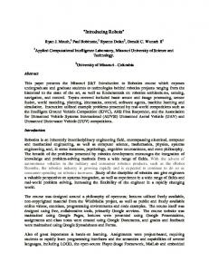
7. Performance Measurements 7.1 General setup of the measurements In order to prove our hypothesis that a goalie with a behavior-based vision system is more robust, we have performed measurements on the behavior of our new goalie. The localisation performance is commonly evaluated in terms of accuracy and/or reactiveness of localisation in test environments dealing with noisy (Gaussian) sensormeasurements (Röfer & Jungel, 2003). We, however, are interested mainly in terms of the system’s reliability when dealing with more serious problems such as large amounts of false sensor data input, or limited amounts of correct sensor input. The ultimate test is how much goals does the new goalie prevent under game conditions in comparison with the old goalie? Due to the hassle and chaotic play around the goal when there is an attack, the goalie easily loses track of where he is. So our ultimate test is now twofold: 1. How fast can the new goalie find back his position in the middle of the goal on a crowded field in comparison with the old goalie 2. How many goals can the new goalie prevent on a crowded field within a certain time slot in comparison with the old goalie All algorithms for the new goalie are made object specific, as described in chapter 4. Since we also want to know the results of using behavior-based perception, results of all realworld scenarios are compared not only to results obtained with the DT2004 system, but also with a general vision system that does implement all object-specific algorithms. The improvements due to object-specific algorithms are also tested offline on sets of images. 7.2 Influence of Object-Specific Image Processing We have compared the original DT2004 image processing with a general version of our NEW image processing; meaning that the latter does not (yet) use behavior specific image processing nor self-localization. In contrast with the DT2004 code, the NEW approach does use object specific grids and color tables. Our tests consisted of, searching for the 2 goals, the 4 flags, and all possible line- and border-points. The images sequences were captured with the robot’s camera, under a large variety of lighting conditions (Figure 15). A few images from all but one of these lighting condition sequences were used to calibrate the ColorTables (CTs). For the original DT2004 code, a single general CT was calibrated for all colors that are meaningful in the scene, i.e.: blue, yellow, white, green, orange and pink. This calibration took three hours. For the NEW image processing code we calibrated five 3-color CTs (for the white-on-green lines, blue-goal, blue-flag, yellow-goal, and yellow-flag respectively). This took only one hour for all tables, so 30% of the original time.
Figure 15. Images taken by the robots camera under different lighting conditions: a) Tubelight; b) Natural-light; c) Tube-light + 4 floodlights + natural light.
79
Behavior-Based Perception for Soccer Robots
For all image sequences that we had acquired, we have counted the number of objects that were detected correctly (N true) and detected falsely (N false). We have calculated also the correctly accepted rate (CAR) being the number of objects that were correctly detected divided by the number of objects that were in principle visible. Table 1 shows the results on detecting flags and lines. The old DT2004 image processor uses a general grid and a single color table, the NEW modular image processor uses object-specific grids and color-tables per object. The calculation of the correctly accepted rate is based on 120 flags/goals that were in principle visible in the first 5 image sequences and 360 flags/goals in principle visible in the set where no calibration settings were made for. The image sequences for line detection each contained on average 31-33 line-points per frame. Goals and flags
DT2004 N true
NEW CAR N false N true (%)
DT2004 NEW CAR (%)
N false
Lines (%)
Lines (%)
1 flood light
23
19
0
65
54
0
18
94
Tube light
54
45
9
83
83
1
58
103
4 flood lights
86
72
0
99
99
0
42
97
Tube +flood lights
41
34
1
110
92
0
24
91
Tube,flood+natural
39
33
0
82
68
0
42
91
Natural light Non calibration set
47
39
0
68
57
0
131
44
28
218
73
16
Table 1. The influence of object-specific algorithms for goal, flag and line detection Table 1 shows that due to using object specific grids and color tables, the performance of the image processing largely increased. The correctly accepted rate (CAR) goes up from about 45 % to about 75%, while the number of false positives is reduced. Moreover, it takes less time to calibrate the color-tables. The correctly accepted rate of the line detection even goes up to over 90%, also when a very limited amount of light is available (1 Flood light). 7.4 Influence of behavior based perception In the previous tests we have shown the improvement due to the use of object specific grids and color tables. Below we show the performance improvement due to behavior based switching of the image processing and the self localization algorithm (the particle filter). We used the following real-world scenarios. • Localize in the penalty area. The robot is put into the penalty area and has to return to a predefined spot as many times as possible within 2 minutes. • Return to goal. The robot is manually put onto a predefined spot outside the penalty area and has to return to the return-spot as often as possible within 3 minutes. • Clear ball. The robot starts in the return spot; the ball is manually put in the penalty area every time the robot is in the return spot. It has to clear the ball as often as possible in 2 minutes. • Clear ball with obstacles on the field. We have repeated the clear ball tests but then with many strange objects and robots placed in the playing field, to simulate a more natural playing environment.
80
Vision Systems: Applications
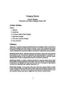
Figure 16. Results for localisation in the penalty area. The number of times the robot can relocalise in the penalty area within 2 minutes. The old DT2004 vision system cannot localise when there is little light (TL). The performance of the object specific image processing (without specific self localisation) is shown by the “flags and lines” bars. In contrast with the DT2004 code, the striker uses object specific image processing. The goalie uses object specific image processing, behavior based image processing and behavior based self localisation In order to be able to distinguish between the performance increase due to object-specific grids and color-tables, and the performance increase due to behavior-dependent image processing and self localisation, we used 3 different configurations. • DT2004: The old image processing code with the old general particle filter. • Striker: The new object-specific image processing used in combination with the old general particle filter of which the settings are not altered during the test. • Goalie: The new object-specific image processing used in combination with objectspecific algorithms for detecting the field lines, and with a particle filter of which the settings are altered during the test, depending on the behavior that is executed (as described in chapter 5). The results can be found in Figures 16-19.
Figure 17. Results of the return to goal test. The robot has to return to its own goal as many times as possible within 3 minutes. The striker vision systems works significantly better than the DT2004 vision system. There is not a very significant difference in overall performance between the striker (no behavior-dependence) and the goalie (behavior dependence). This shows that the checking mechanism of the “in goal” assumption works correctly
Behavior-Based Perception for Soccer Robots
81
Figure 18. (left). Results of the clear ball test. The robot has to clear the ball from the goal area as often as he can in 2 minutes. Both the striker and the goalie vision systems are more robust in a larger variety of lighting conditions than the DT2004 vision system (that uses a single color table). The goalie’s self-locator, using detected lines and the yellow flags, works up to 50 % better than the striker self-locator, which locates on all line-points, all flags and goals Figure 18 (right). Results of the clear ball with obstacles on the field test. The goalie vision system, which uses location information to disregard blue flags/goals and only detects large yellow flags, is very robust when many unexpected obstacles are visible in or around the playing field.
8. Results •
• • •
• •
The impact of behavior-based perception can be seen from the localization test in the penalty area (Figure 16) and from the clear-ball tests (Figure 18). The vision system of the goalie, with behavior based vision and self localisation, performs > 50 % better on the same task as a striker robot with a vision system without behavior-based perception. With object-specific grids and color-tables, the performance of the image processing (reliability) under variable lighting conditions has increased with 75-100% on sets of offline images, while the color calibrating time was reduced to 30%. Behavior-based perception and object-specific image processing combined allows for localization in badly lighted conditions, e.g. with TL tube light only (Figure 16-18). The impact of discarding unexpected objects on the reliability of the system can most clearly be seen from the clear ball behavior test with obstacles on the field (Figure 18, right). With TL + Floods, the striker apparently sees unexpected objects and is unable to localize, whereas the goalie can localize in all situations. Using all object specific image processing algorithms at the same time requires the same CPU load as the old general DT2004 image processor. Searching for a limited number of objects in a specific behavior can therefore reduce the CPU load considerably. Due to the new architecture, the code is more clean and understandable; hence better maintainable and extendable. The main drawback is that one has to educate complete system engineers instead of sole image processing, software, AI, and mechanical experts.
82
Vision Systems: Applications
9. References Arkin, R.C. (1998). Behavior based robotics, MIT press, ISBN 0-262-01165-4 Brooks, R.A. (1991). Intelligence without Representation. Artificial Intelligence, Vol.47, 1991, pp.139-159. Bruce, J.; Balch, T. & Veloso, M (2000). Fast and inexpensive color image segmentation for interactive robots. In Proceedings of the 2000 IEEE/RSJ International Conference on Intelligent Robots and Systems (IROS '00), volume 3, pages 2061-2066. Dietterich, T.G (2000). Hierarchical reinforcement learning with the MAXQ value function decomposition. Journal of Artificial Intelligence Research, 13:227-303, 2000 Jonker, P.P.; Terwijn, B; Kuznetsov, J & van Driel, B (2004). The Algorithmic foundation of the Clockwork Orange Robot Soccer Team, WAFR '04 (Proc. 6th Int. Workshop on the Algorithmic Foundations of Robotics, Zeist/Utrecht, July), 2004, 1-10. Lenser, S; Bruce, J & Veloso (2002). M. A Modular Hierarchical Behavior-Based Architecture, in RoboCup-2001, Springer Verlag, Berlin, 2002. Lötzsch, M.; Back, J.; Burkhard H-D & Jüngel, M (2004). Designing agent behavior with the extensible agent behavior specification language XABSL. In: 7th International Workshop on Robocup 2003 (Robot World Cup Soccer Games and Conferences in Artificial Intelligence, Padova, Italy, 2004. Mantz, F. (2005). A behavior-based vision system on a legged robot. MSc Thesis, Delft University of Technology, Delft, the Netherlands. Mantz, F; Jonker, P; Caarls W (2005); Behavior-based vision on a 4-Legged Soccer Robot. Robocup 2005, p. 480-487 Oomes, S; Jonker, P.P; Poel, M; Visser, A & Wiering, M (2004). The Dutch AIBO Team 2004, Proc. Robocup 2004 Symposium (July 4-5, Lisboa, Portugal, Instituto Superior Tecnico, 2004, 1-5. see also http://aibo.cs.uu.nl Parker, L.E. (1996). On the design of behavior-based multi-robot teams. Journal of Advanced Robotics, 10(6). Pfeifer, R & Scheier, C (1999). Understanding Intelligence. The MIT Press, Cambridge, Massechussets, ISBN 0-262-16181-8. Röfer, T, von Stryk, O, Brunn, R; Kallnik, M and many other (2003). German Team 2003. Technical report (178 pages, only available online: http://www. Germanteam.org/GT2003.pdf) Röfer, T. & Jungel, M. (2003). Vision-based fast and reactive monte-carlo localization. In The IEEE International Conference on Robotics and Automation, pages 856-861, 2003, Taipei, Taiwan. Sutton, R.S & Barto, A.G (1998). Reinforcement learning – an introduction., MIT press, 1998. ISBN 0-262-19398-1. Takahashi, Y & Asada, M (2004). Modular Learning Systems for Soccer Robot (Takahashi04d.pdf). 2004, Osaka, Japan. Thrun, S.; Fox, D.; Burgard, W & Dellaert (2001), F. Robust monte carlo localization for mobile robots. Journal of Artificial Intelligence, Vol. 128, nr 1-2, page 99-141, 2001, ISSN:0004-3702 Thrun, S. (2002). Particle filters in robotics. In The 17th Annual Conference on Uncertainty in AI (UAI), 2002