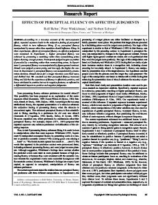
on caregivers, and promotes a feeling of self-reliance and self-esteem. Unfortunately, some ... The CALL Centre of the University of Edinburgh has developed a ...
Behavior-based Perceptual Navigation for Semi-autonomous Wheelchair Operations Hajime Uchiyama and Walter D. Potter Artificial Intelligence Center, University of Georgia, Athens, GA, USA
Abstract— This paper describes an overview of our semiautonomous (SA) wheelchair prototype and emphasizes the design of the perceptual navigation system. The goal of our project is to increase independent mobility of individuals who are wheelchair-bound and severely vision impaired, and the scope of the project focuses on developing the perceptual navigation system that is equipped with sonar sensors, a motorized camera system, and a tactile feedback system. We present an overview of a customized Behaviorbased control architecture: Behavior Cell and Behavior Network components, and implementation of behaviors such as obstacle notification, free-space finding, and doorway navigation. Keywords: Robotics, Semi-autonomous Wheelchair, Perceptual Navigation, Behavior-based Control, Tactile Feedback
1. Introduction Studies have shown that individuals with disabilities, regardless of their age, benefit substantially from access to independent mobility, including electrically powered wheelchairs ([1], [2], [3]). Independent mobility increases vocational or educational opportunities, reduces dependence on caregivers, and promotes a feeling of self-reliance and self-esteem. Unfortunately, some individuals are unable to independently operate a powered wheelchair due to their impairments of motor, sensory, perceptual, or a combination of these capabilities. In order to assist those individuals, a number of studies have been conducted in the field of assistive technology which combine robotics and artificial intelligence to develop robotized wheelchairs; some try to achieve autonomous control over the wheelchairs, and others aim for semiautonomous control. Most of these robotized wheelchairs are equipped with a computer and a set of sensors, such as cameras, infrared sensors, ultrasonic sensors, and laser rangers. This assortment of equipment is used to address a number of specific problems such as: obstacle avoidance, local environment mapping, and route navigation. The CALL Centre of the University of Edinburgh has developed a wheelchair intended to be used by children who do not have the physical, perceptual or cognitive abilities to control an ordinary powered mobility aid [4]. The Smart Wheelchair exhibits collision detection followed
by a maneuvering action, following the line tracks laid along the floor, and communication between the user via a speech synthesizer or other feedback system. The TAO series (Applied AI Systems Inc.) is mainly designed for research and development purposes. TAO-7 is equipped with a voice recognition/synthesis interface and performs freespace detection in a crowd and landmark-based navigation in addition to the common tasks such as obstacle avoidance [5]. The Tin Man project at the Kiss Institute is aimed at the development for a low-cost robotic wheelchair to aid people with impaired mobility [6]. Tin Man II exhibits manual navigation with obstacle avoidance override, autonomous control, and manual mode. The Wheelesley project at MIT intends to be used by users unable to manipulate the standard motorized wheelchair and aims to establish the system for both indoor and outdoor navigation. Wheelesley was developed based on the Tin Man model and interacts with the seated user via a graphical user interface [7]. The NavChair system (University of Michigan) , one of the most successful systems in the ’90s, intends to provide mobility support to users who are unable to drive standard motorized wheelchairs by autonomously selecting three different modes (tasks): obstacle avoidance, door passage, and wall following [8]. Despite these efforts, very few robotized wheelchairs are currently observed in the market, and none are intended to be used outside of a research lab or a training facility. The above studies are mainly issuing an autonomous control system. With autonomous control, the system probes the environment, detects an obstacle, plans a navigation route, makes decisions, and fully controls the mobility of the wheelchair, which leaves the user totally dependent upon the equipment. While some users might be comfortable with an autonomous wheelchair transportation system, others want to be more involved with the process. It is essential for them to feel as if, or actually, they are in control, while being responsible for both the decision-making and motion of everyday transportation activities rather than being a passenger.
1.1 Semi-autonomous Wheelchairs The purpose of developing a semi-autonomous (SA) wheelchair system, while it comprises hardware equipment similar to autonomous wheelchairs, focuses on providing just
as much assistance as the user really needs, in order to enhance the level of autonomy of the user. Generally, the type of assistance for a user varies from one to another; therefore, the specification of an SA wheelchair system needs to be determined based on the user’s physical conditions. A number of research projects have been actively conducted to provide various types of semi-autonomous wheelchairs. Borgolte et al. provided omnidirectional maneuverability to allow an intuitive semi-autonomous control system to assist people with severe or multiple handicap [9]. Argyros et al. presented a semi-autonomous navigation system comprising a panoramic vision system to support the users with limited motor control of the upper extremities [10]. The Mobile Internet Connected Assistant (MICA) project designed a system in which the user either locally or remotely controls the chair by means of head-held sensors [11]. Although using a slightly different platform, a powerassisted manual wheelchair,1 Simpson et al. demonstrated the first prototype which attempts to provide users who have visual impairments with some basic navigation tasks such as collision avoidance [12] . However, none of these systems provide or enhance perceptual capabilities for the seated user who has severe visual impairment. The goal of our SA wheelchair project is to increase independent mobility of individuals who are wheelchair-bound and severely vision impaired by providing a perceptual navigation system. The scope of the project focuses on developing the perceptual navigation system with certain autonomy, but not on controlling the movement of the wheelchair, in order to enable the user to maintain the maximum control over the wheelchair movement.
2. Design 2.1 Behavior Cell Approach Since the SA wheelchair system needs to be individualized to the user, our design principle shall be based upon modularity and flexibility. Further, due to the nature of the navigational tasks required during wheelchair operations, which must be resolved quickly and handled concurrently, the behavior-based control (BBC) architecture ([13], [14], [15]) is suitable for the base architecture of our design. Utilizing a customized BBC architecture, we define behaviors which emerge from an agent-environment interaction based on a number of loosely tied processes that run asynchronously and respond to problems in a parallel manner. In our project, behaviors are realized to accomplish their tasks through user-machine cooperation. Two cooperating behaviors, the Perceptual Behaviors and Navigational Behaviors, acquire the state of the environment through sensors, interpret or respond to the state, and pass the naviga1 Based on a manual wheelchair, the rear wheel hubs are replaced with motorized ones that magnify and/or adjust the propulsive force provided by the user.
Fig. 1: The basic structure of a Behavior Cell.
tional signals to the user. Finally the user manipulates the wheelchair in combination with his/her own perception and judgment (Manipulative Behaviors). 2.1.1 Behavior Cell We present a unit of the behavioral structure, a Behavior Cell, which is based upon the BBC architecture with the extended input/output feature. A Behavior Cell consists of an input/output (I/O) component, a behavioral function component, and an internal storage component (Figure 1). It structurally resembles an artificial neuron; however, it has a logical gate in addition to widely extended functions such that the innervation link between cells can run by both Boolean and numeric means. The I/O component consists of a subset of the I/O ports characterized as follows: Port-EB, excitatory inputs; Port-IB, inhibitory inputs; Port-DI, sensory/behavioral inputs; PortRS, a reset signal; Port-IS, an innervation signal; Port-AB, an activation output; Port-EO, an effect output; and PortAO, actuator outputs. The excitatory and inhibitory inputs are linked to the corresponding behaviors’ activation output ports. When any activation/inhibition conditions are met, the behavior is activated/deactivated. Our architecture allows both Port-EB and Port-IB to specify activation (inhibition) conditions by using logical expressions. Port-DI takes various types of data inputs from sensors or other behaviors (effect outputs). When Port-IS receives an innervation signal from outside, the behavior checks or sends its inputs and outputs. If Port-RS receives a reset signal, the behavior will clear all or specified dynamic data. PortAB contains an activation value (binary) that is linked to the value of Port-EB. Port-EO contains an effect value that is derived from the behavioral function. If the behavior is connected to its effector(s), Port-AO sends Action Outputs to them. The behavioral function component provides a flexible activation/computation functionality, such as algebraic sum, sigmoid, Gaussian, and logical expressions, as well as a simple by-pass function (e.g. a direct link between inputs and outputs). More complicated functionalities, such as fuzzy logic inference operators or artificial neural networks, can
also be implemented. The storage component provides a storing capability of the current state onto its dynamic data, which enables the behavior to achieve goals that contain temporal sequences. It may also contain internal static data which all instantiated behaviors can share and refer to, as well as individual constant data that a behavior utilizes as permanent reference information, such as threshold values or look-up tables. The activation/computation process performed by a Behavior Cell is as follows: 1) When Innervation Input (Port-IS) receives a signal, check the value of Effect Inputs (Port-EB). If true, set Activation Output (Port-AB) value to 1 (true) and go to the next step, otherwise return. 2) Check the value of Inhibitory Inputs (Port-IB) to see whether the behavior is inhibited. If false, go to the next step, otherwise set Activation Output (Port-AB) to 0 (false) and return. 3) Check the value of Reset input (Port-RS), and if true, clear the dynamic data. 4) In case of using Port-EO: Using the information from Sensors/Behavior Inputs (Port-DI), derive the return value from the behavioral function and write this value to Effect Output (Port-EO) and return. Store the necessary data in the internal memory if so designed. 5) In case of using Port-AO: Similar to (4), derive the return action commands from the behavioral function and send the commands to the effectors via Action Outputs (Port-AO) and return. Store the necessary data in the internal memory if so designed. 2.1.2 Behavior Network Similar to other Behavior-Based architectures (for instance, [16]), our approach also enables behaviors to consist of other behaviors (Behavior Network). In a Behavior Network, behaviors communicate with each other through their port-to-port links, and precondition dependence characterizes the links; thus, the activation of a behavior is dependent on its pre-conditional links. An individual Behavior Cell can connect to multiple Behavior Cells, and similarly, multiple Behavior Cells can be linked to a single Behavior Cell. This multiple-connectivity allows a Behavior Cell to be a member of multiple Behavior Networks, which makes component-like behaviors, such as interface to the sensors, reusable. Containing multiple task-oriented/reactive behaviors (functional cells) enables a Behavior Network to accomplish various tasks, such as command arbitration, learning, and planning, while asynchronously performing tasks within the distributed architecture. In order for a Behavior Network to behave as structurally equivalent as a Behavior Cell when observed from outside, each Behavior Network must contain a set of specific types of Behavior Cells: Boolean I/O cells to handle the
Innervation Excitatory Inputs
Activation Output Excitatory link Inhibitory link Data link Innervation link Actuator link
Inhibitory Inputs
Functional Cell Reset
I/O Cell
Fig. 2: Schematic diagram of I/O links in a Behavior Network.
excitatory/inhibitory signals, and activation I/O cells for scheduling the sequence of activating functional cells in the Behavior Network. The functional cells deal with data and/or actuator communication. Connections between functional cells consist of excitatory links (between Port-AB and Port-EB), inhibitory links (between Port-AB and Port-IB), (sensory and/or behavioral) data links (between Port-EO and Port-DI), and actuator links (between Port-AO and effectors). A functional cell in a Behavior Network can also be another Behavior Network. Figure 2 illustrates a generic Behavior Network that consists of I/O cells and functional cells. When an innervation cell first receives a signal, it sends signals to the Excitatory Inputs cell, Inhibitory Inputs cell, and Activation Output cell in this order. When the Activation Output cell receives the innervation signal, it also receives the excitatory and inhibitory signals from Excitatory/Inhibitory Inputs cells; therefore, it can compute its activation value, which in turn represents the activation status of the whole Behavior Network. The activation value is written in Port-AO (activation output) of the Activation Output cell, and if the value is true, the Activation Output cell starts sending the innervation signals to the functional cells in a predefined order, otherwise the whole process will return; thus the Behavior Network will be deactivated.
2.2 System Components In this section, we briefly overview the system components of our SA wheelchair prototype. The major add-on hardware to the base wheelchair (Invacare Nutron® R32) comprises stationary ranging modules, motorized vision modules, and the tactile feedback module. The stationary ranging module is a collection of ultrasonic sensors (Devantech SRF-08) which are attached to the wheelchair and constantly measure distances to any objects that are within the scope of the sensors. Six sonars are equipped to the front side, and two sonars are placed to the rear side, as illustrated in Figure 3.
Front Left
Front-Side Left
Front Right
Front-Side Right
Front
Side Left
Side Right
Wheelchair
Back Back Left
Back Right
Fig. 5: Vibrotactors on the Vibrotactile Glove.
Fig. 3: Schematic diagram of installation of sonars. Camera
generated by different vibrotactors. We also designed a motor-array controller which controls the vibrotactors based on commands sent from the host computer via a RS-232C.
Sonar
3. Behavior Implementation Laser Line Generator
Servo (Tilt)
Servo (Pan)
Fig. 4: Motorized vision module.
We designed a customized motorized vision module (Figure 4) which consists of low cost components: a webcam (Logitech QuickCam® Pro 4000), laser line generator, and tilt/pan servo motors. It is capable of tilting (0–135°) and panning (0–360°) and acquires depth data as well as scenery images. The above sensor system is controlled by a microcontroller (Rowely Associates Ltd. CrossFire® LPC-2138 evaluation kit) which is connected to the host computer via a USB port. The tactile feedback module is designed to convey vibrotactile signals to assist users to manipulate the SA wheelchair. We have developed a Vibrotactile Glove which consists of an array of vibrotactors inside the glove on the back side of the hand (Figure 5). Each vibrotactor is iconically mapped to represent the spatial positioning around the wheelchair, such as vibrotactor 1 for front; 3, left; 5, right; 7, rear; 4, center; and so forth. A vibrotactor generates a vibrotactile stimulus consisting of a rapid vibration lateral to the skin surface, and its characteristic is determined by the duration of stimulus and the inter-stimuli interval. A sequential stimulus consists of a sequence of multiple vibrotactile stimuli
The perceptual behaviors of interest in this paper are Obstacle notification, Free-space finding, and Doorway navigation, each of which is a Behavior Network consisting of a set of other Behavior Cells or Behavior Networks. The navigational behavior is represented as the Navigation command manager, and the Sensor command manager manages the commands for the sensor-related effectors (servo motors and the laser line generator). Figure 6 illustrates the schematic diagram of the perceptual and navigational behaviors accompanied with the sensor-effector systems. The thin arrows represent data links, and the thick arrows represent actuator links. Other port-to-port links are not shown. The following subsections briefly describes the implementation of Obstacle notification, Free-space finding, Doorway navigation, Sensor command manager, and Navigation command manager behaviors.
3.1 Obstacle Notification The Obstacle notification behavior is a reactive behavior which takes sensor readings from the ultrasonic sensors and directly maps into vibrotactile representations. It consists of one subordinate behavior, Sonar reader, and two internal functions: decodePacket and translateData (Figure 7). The Sonar reader behavior is a component-like behavior which reads ranging data from the ultrasonic sensors. The decodePacket function decodes the data packet from the Sonar reader behavior into an array of ranging data. The translateData function interprets a numeric value of ranging data into a discrete representation which expresses the distance of an obstacle within the scope of each sensor.
3.2 Free-space Finding The Free-space finding behavior is, by default, another reactive behavior relating to the sensor readings, but
Camera Input
Doorway Navigation
Servos Sensor Command Manager
Motion Sensor Input
Free-space Finding
Sonar Input
Obstacle Notification
Sensor Controller Laser
Navigation Command Manager
Motor Array Controller
Vibrotactile Glove
Fig. 6: Schematic diagram of the perceptual and navigational behaviors (thin arrows: data links, thick arrows: actuator links).
Obstacle Notification Sonar sensors Sensor reader
translateData
Behavior
Sonar sensors
Free-space Finding Sensor reader
function
Port-IB
decodePacket
Output data
Way finder
Behavior
Data link Actuator link
decodePacket
Output data
Fig. 7: Schematic diagram of the Obstacle notification behavior.
its task is different from the Obstacle notification behavior. Instead of notifying of obstacles, it reports a list of orientations in which no immediate obstacles are found. This behavior is particularly effective to find a way out when the SA wheelchair is surrounded by many obstacles. It consists of an internal function decodePacket and three subordinate behaviors: Sonar reader, Range finder, and Way finder (Figure 8). The Free-space finding behavior primarily relies on sonar readings from the Sonar reader behavior, and utilizes the Way finder behavior to find a list of obstacle-free orientations. If the Way finder behavior finds that the sonar readings do not provide enough information, it will send a request to the Sensor command manager behavior to move the pan servo motor and will also invoke the Range finder behavior to acquire more accurate depth information. Since the Range finder behavior is connected to multiple behaviors, the Sensor command manager behavior may not allow the Way finder behavior to control the Range finder behavior in order to avoid conflicts. If that is the case, the Sensor command manager behavior will send an inhibitory signal to Port-IB of the Free-space finding behavior, which is directly connected to the same port of the Way finder behavior. The Way finder behavior will then return the list that contains a null value to indicate that no available orientations are found.
3.3 Doorway Navigation The task of passing through a doorway, in general, comprises several subtasks addressing dynamic determination of a maneuvering trajectory and decision making which relies on high level cognitive processes. Some previous
Sensor command manager
Camera
function
Range finder
Excitatory link Inhibitory link Data link Actuator link
Fig. 8: Schematic diagram of the Free-space finding behavior.
Fig. 9: Schematic diagram of a maneuvering trajectory for passing through a doorway.
studies demonstrate the creation of a local map in order to generate a maneuvering trajectory for an autonomous vehicle ([17], [18]). Such maneuvering trajectories typically shape a smooth curvature as illustrated in Figure 9. However, generating such trajectories requires much finer angular guidance than the one that the vibrotactile signals can convery. Our guidance approach utilizes the Pivotal Point/Zone, an intermediate goal point (area) from which the wheelchair can straightforwardly move toward the doorway, to create a Pivotal-zone trajectory that consists of a series of simplified wheelchair movements. In contrast with the maneuvering trajectory in Figure 9, the Pivotal-zone trajectory in Figure 10 consists of distinctly separated components: a series of nearly straight lines and a sharp turning point. By splitting the trajectory into those components, our approach enables each step of the wheelchair movement to be translatable into a simple and intuitive vibrotactile representation, such as “go
doorway and then to move forward.
3.4 Sensor command manager
Fig. 10: Schematic diagram of a Pivotal-zone trajectory for passing through a doorway. Doorway navigation
Boolean I/O* Sensory input*
Object tracker
Doorway detection
External Sensor command manager
Doorway validation
Camera input Range finder Excitatory link Inhibitory link Data link Actuator link
Laser Module
Path planner Sensory input*
Pan/tilt servos
Boolean I/O* Output data
* Identical component/behavior
Fig. 11: Schematic diagram of the Doorway navigation Behavior Network.
front-left,” “swivel clockwise,” or “go forward.” Figure 11 illustrates the Doorway navigation behavior which comprises the following behaviors: Doorway detection, Range finder, Door validation, Object tracker, and Path planner. The Doorway detection behavior searches for a doorway candidate in the image stream by classifying the presence of a doorframe. If it finds a candidate, the Door validation behavior is invoked to confirm the validation of the candidate. The Door validation behavior then activates the Range finder behavior that measures the depth information in the image by detecting the horizontally emitted laser line based on the triangulation principle. Both Doorway detection and Range finder behaviors constitutes computer-vision based algorithms to accomplish their tasks, but the details are beyond the scope of this paper. Once the doorway is confirmed, the Object tracker behavior traces the door in order to fixate the camera to the doorway. In the mean time, the Path planner behavior is invoked to undertake navigation to a pivotal zone, which comprises a repetitive process of localizing the wheelchair, adjusting the path, and sending a signal indicating the orientation to the user, until the wheelchair reaches that zone. At the pivotal zone, the Path planner guides the user to swivel until the wheelchair straightforwardly faces the
In case a functional cell connected to multiple cells must uniquely communicate with one cell at a time, for instance, if a camera-controlling cell is connected to two different possibly conflicting Behavior Cells, the Sensor command manager behavior will handle the tasks similar to a hardware interrupt based on a list of predefined priority of linked Behavior Cells. The Sensor command manager behavior receives input commands from the Doorway navigation and the Free-space finding behaviors, more specifically, the Object tracker and Range finder behaviors in the Doorway navigation behavior, and the Way finder and Range finder behaviors in the Free-space finding behavior. Since the Doorway navigation and Free-space finding behaviors have different areas of interest for ranging, the Range finder behavior must be exclusively controlled by either one of them. The priority is given to the Doorway navigation behavior; therefore, when the Object tracker and Range finder behaviors in the Doorway navigation behavior are active, a control request of the servo motors from the Free-space finding behavior is suppressed. The Sensor command manager behavior achieves this task by sending an inhibitory signal to the Free-space finding behavior.
3.5 Navigation command manager The Navigation command manager behavior accepts navigation commands from the Doorway navigation, Free-space finding, and Obstacle notification behaviors, arbitrates the commands, and generates a vibrotactile representation. It consists of four internal functions: gateSignals, selectSignal, encodePacket, and mergeCommands (Figure 12). Let Commanddoor denote the command from the Doorway navigation behavior; Commandfree , the Free-space finding behavior; and Commandobs , the Obstacle notification behavior, respectively. The gateSignals function accepts Commandfree , which will be one of the following: a list of obstaclefree orientations, the “stop-the-chair” signal (no free-space is found), or a null code (the Doorway navigation behavior is active). The “stop-the-chair” signal is sent to the selectSignal function, and the null code is sent to the mergeCommands function. If Commandfree consists of a list of obstacle-free orientations, it will be sent to both. By default, Commandobs is sent to the encodePacket function to generate a series of control codes (a vibrotactile representation) to be passed to the motor-array controller. However, when more than two immediate obstacles are found in Commandobs , the selectSignal function
Doorway navigation
Navigation command manager
Vibrotactile motor controller
mergeCommands Free-space finding
encodePacket
Behavior function
gateSignals Obstacle notification
Data link
selectSignal
Fig. 12: Schematic diagram of the Navigation command manager behavior.
chooses the most appropriate orientation from the list of obstacle-free orientations in Commandfree . When the Doorway navigation behavior is activated, both Commanddoor and Commandfree are sent to the mergeCommands function to find an orientation that satisfies both constraints. If Commandfree consists of a null code, the mergeCommands function simply chooses Commanddoor to be sent to the encodePacket function. If Commandfree consists of a list of obstacle-free orientations, the mergeCommands function tries to find the closest orientation to the one from Commanddoor . Once the mergeCommands function issues a new command, the encodePacket function only takes that command and ignores Commandobs . The encodePacket function generates a control code to be executed by the Vibrotactile motor controller behavior to generate a vibrotactile signal to the Vibrotactile Glove. The vibrotactile signals consist of a warning signal (e.g., “stop-the-chair”), spatial representation (the presence of obstacles), and directional guidance.
4. Current Status Currently we are in the process of implementing the behaviors and are close to completion. Experimental field tests of the SA wheelchair operation are underway.
5. Conclusion In this paper, we proposed a customized BBC architecture to design the perceptual behaviors for the SA wheelchair operations. Although the experimental field tests are still underway, the Behavior Cell and Behavior Network components provide flexibility, extensibility, and polymorphism in design which enables more intuitive implementation of a planning oriented task for our SA wheelchair project compared to a standard BBC architecture.
References [1] J. Douglass and M. Ryan, “A pre-school severely disabled boy and his powered wheelchair: A case study,” Child Care, Health Development, vol. 13, pp. 303–309, 1987.
[2] K. Paulsson and M. Christoffersen, “Psychosocial aspects of technical aids - how does independent mobility affect the psychosocial and intellectual development of children with physical difficulties?” in Proc. 2nd Int. Conf. of the Rehabilitation Engineering Society of North America, Ottawa, 1989, pp. 282–285. [3] G. Verburg, L. Balfour, E. Snell, and S. Naumann, “Mobility training in the home and school environment for persons with developmental delay,” in Final Report to Ontario Mental Health Foundation and Ministry of Community and Social Services’ Research and Program Evaluation Unit, 1991. [4] J. Odor and M. Watson, “Learning through smart wheelchairs: A formative evaluation of the effective use of the call centre’s smart wheelchairs as part of children’s emerging mobility, communication, education and personal development,” Final Report to The Nuffield Foundation and the Scottish Office Education Department, Tech. Rep., May 1994. [5] T. Gomi and A. Griffith, “Developing intelligent wheelchairs for the handicapped,” in Assistive Technology and Artificial Intelligence, Applications in Robotics, User Interfaces and Natural Language Processing, ser. Lecture Notes in Computer Science, V. O. Mittal, H. A. Yanco, J. M. Aronis, and R. C. Simpson, Eds., vol. 1458. New York: Springer, 1998, pp. 150–178. [6] D. P. Miller and M. G. Slack, “Design and testing of a low-cost robotic wheelchair prototype,” Autonomous Robots, vol. 2, no. 1, pp. 77–88, Mar. 1995. [7] H. A. Yanco, “Wheelesley: A robotic wheelchair system: Indoor navigation and user interface,” Lecture Notes in Computer Science, vol. 1458, p. 256, 1998. [8] S. P. Levine, D. A. Bell, L. A. Jaros, R. C. Simpson, Y. Koren, S. Member, and J. Borenstein, “The NavChair assistive wheelchair navigation system,” IEEE Transactions on Rehabilitation Engineering, vol. 7, pp. 443–451, June 21 1999. [9] U. Borgolte, H. Hoyer, C. Bühler, H. Heck, and R. Hoelper, “Architectural concepts of a semi-autonomous wheelchair,” Journal of Intelligent and Robotic Systems, vol. 22, no. 3, pp. 233–253, Jul. 1998. [10] A. A. Argyros, P. Georgiadis, P. Trahanias, and D. P. Tsakiris, “Semi-autonomous navigation of a robotic wheelchair,” Journal of Intelligent and Robotic Systems, vol. 34, pp. 315–329, Mar. 02 2002. [11] S. Rönnbäck, J. Piekkari, K. Hyyppä, T. Berglund, and S. Koskinen, “A semi-autonomous wheelchair towards user-centered design,” in ICCHP, ser. Lecture Notes in Computer Science, K. Miesenberger, J. Klaus, W. L. Zagler, and A. I. Karshmer, Eds., vol. 4061. Springer, 2006, pp. 701–708. [12] R. Simpson, E. LoPresti, S. Hayashi, S. Guo, D. Ding, W. Ammer, V. Sharma, and R. Cooper, “A prototype power assist wheelchair that provides for obstacle detection and avoidance for those with visual impairments,” Journal of NeuroEngineering and Rehabilitation, vol. 2, no. 1, p. 30, 2005. [13] R. C. Arkin, Behavior-Based Robots. Cambridge, Massachusetts: The MIT Press, 1998. [14] R. A. Brooks, “Integrated Systems Based on Behaviors,” SIGART Bulletin, vol. 2, no. 4, pp. 46–50, 1991. [15] M. J. Matari´c, “Behavior-based control: Main properties and implications,” in IEEE International Conference on Robotics and Automation, Workshop on Architectures for Intelligent Control Systems, Nice, France, may 1992, pp. 46–54. [16] M. N. Nicolescu and M. J. Matari´c, “A hierarchical architecture for behavior-based robots,” in Proceedings of the First International Joint Conference on Autonomous Agents and Multiagent Systems (AAMAS’02), M. Gini, T. Ishida, C. Castelfranchi, and W. L. Johnson, Eds. ACM Press, Jan. 17 2002. [17] S. Patel, S.-H. Jung, J. P. Ostrowski, R. Rao, and C. J. Taylor, “Sensor based door navigation for a nonholonomic vehicle,” in IEEE International Conference on Robotics & Automation, Washington, DC., May 2002, pp. 3081–3086. [18] H. Surmann, A. Nüchter, and J. Hertzberg, “An autonomous mobile robot with a 3D laser range finder for 3D exploration and digitalization of indoor environments,” Robotics and Autonomous Systems, vol. 45, no. 3-4, pp. 181–198, 2003.