Electronic Notes in Theoretical Computer Science 264 (2010) 91–105 www.elsevier.com/locate/entcs
Behaviour-Driven Development of Foundational UML Components Ioan Laz˘ar1 ,2 Simona Motogna1 ,3 Bazil Pˆarv1 ,4 Department of Computer Science Babe¸s-Bolyai University Cluj-Napoca, Romania
Abstract Behaviour-Driven Development (BDD) focuses all development activities on the delivery of behaviours what a system should do, described such that developers and domain experts speak the same language. BDD frameworks allow users to represent the required system behaviour as executable user stories and the acceptance criteria as executable scenarios attached to user stories. In this paper we define a UML profile that allows users to create executable Foundational UML (fUML) stories and scenarios. In order to easily construct scenarios we introduce a BDD model library which contains fUML activities for testing equalities and inclusions. We also present an Eclipse-based development tool that supports a BDD approach for developing fUML components. The tool provides developers a concrete syntax for defining executable scenarios, and automatically updates the project status based on verified delivered behaviorus. Keywords: behaviour-driven development, executable UML, user story, executable specification, acceptance criteria
1
Introduction
BDD [17] is an agile software development approach that encourages collaboration between all project participants. BDD is an evolution of test-driven development (TDD) [3] and acceptance test-driven planning. The most important core principle of BDD says that “business and technology people should refer to the same system in the same way” [4]. In order to achieve this objective, a common (ubiquitous) language is needed for specifying system behaviours, allowing: (a) the customers to specify the requirements from a business perspective, (b) the business analysts to attach concrete examples (scenarios 1
This work was supported by the Grant ID 546, sponsored by NURC - Romanian National Research Council(CNCSIS). 2 Email:
[email protected] 3 Email:
[email protected] 4 Email:
[email protected]
1571-0661/$ – see front matter © 2010 Elsevier B.V. All rights reserved. doi:10.1016/j.entcs.2010.07.007
92
I. Laz˘ar et al. / Electronic Notes in Theoretical Computer Science 264 (2010) 91–105
or acceptance tests) that clarify the system behaviour, and (c) the developers to implement the required system behaviour in a TDD manner. User stories represent “high-level definitions of requirements with just enough information to produce effort estimation” [2], so, from a customer perspective, they are appropriate candidates for describing the system behaviour. In order to permit developers and domain experts speak the same language, a domain specific language (DSL) is needed for defining the scenarios attached to a story. The second core principle of BDD says that “any system should have an identified, verifiable value to the business” [4]. Organizing the development effort around the system behaviour could achieve the first objective, but how could we know when we have delivered a behaviour? If the behaviour is described using executable scenarios (executable acceptance tests) then the software can be automatically verified through succesful passing of the tests. Applying these agile principles in a model-driven development (MDD) context can be beneficial for both worlds. MDD approaches rely on the use of models to represent the system elements. There are two variants of MDD approaches: focused on using domain specific modeling languages (DSML) and based on OMG’s ModelDriven Architecture (MDA) [18] which relies on using the UML [25] along with specific profiles. The MDA approach is favored over the use of DSML since UML is a widely accepted modeling language. A particular class of MDA processes which can be merged with a BDD approach is agile MDA processes [14] which applies agile principles (e.g. testing first, immediate execution) into a classical MDA process. For such processes models act just like code. Executable UML [15] means an execution semantics for a subset of actions sufficient for computational completeness. Today, the effort of defining a standard execution semantics enters the final state of adoption. Foundational UML (fUML) defines a “basic virtual machine for the UML, and the specific abstractions supported thereon, enabling compliant models to be transformed into various executable forms” [23]. In this paper we define a UML profile that allows developers to build fUML models using a BDD approach. We also define a BDD library containing activities that can help users to build executable scenarios. In order to easily construct executable scenarios we introduce a concrete syntax for BDD scenarios and we discuss the relationship of this syntax to the expected standardized action language, currently under development [22]. A BDD tool (bUML) for fUML models is also presented. This tool supports all BDD activities and automatically updates the project status after scenario execution. In section 2 we present the general context for BDD and MDD. The third and fourth sections present the proposed UML profile and library, and Section 5 describes our development tool. In section 6 we discuss related work, while the last section contains conclusions and future works.
I. Laz˘ar et al. / Electronic Notes in Theoretical Computer Science 264 (2010) 91–105
2
93
Background
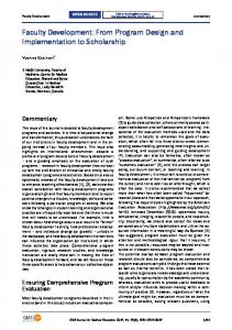
When Dan North introduced BDD [17] he proposed an ubiquitous language for analysis, so that the requirements can be captured into the codebase. This language represents the requirements as user stories, and the acceptance criteria as scenarios attached to user stories. He proposed the following standard form for writing scenarios: given some initial context, when an event occurs, then ensure some outcomes. In order to verify automatically whether a given story is implemented, he suggested that scenarios must be written as test cases. In what follows we are going to analyze these concepts from two perspectives: agile project planning and execution frameworks. The figures presented in this section represent design artifacts of our development framework presented in Section 5. Project name /estimate /progress
has
0..*
Iteration number
has
0..* User
Scenario -status ScenarioStatus name -owner 0..1 description 0..* Pending is in charge of Failure contains 0..* Success 0..* Story validated by StoryStatus id Defined name Inprogress text has Accepted estimate 0..* -status 0..* proirity Completed 0..*
Fig. 1. The main concepts of BDD
Agile project planning. Figure 1 presents a domain model that captures the main concepts of BDD. A Project has many Stories which describe the project requirements, each Story being validated by Scenarios. A Project has Users which may have attached roles such as customers, analysts, and developers. The Stories are used to estimate the development time and to assign Users to implement the required functionality. BDD is an iterative development approach, so Stories are allocated to Iterations. These concepts are also used in card-based planning where customers and developers use story cards to represent user stories (see e.g. [1]). Requirements analysis Project planning Development iteration Verifiable progress
US1. Users add new stories to a project US2. Users add new scenarios to a story US3. Users add new iterations to a project US4. Users allocate stories to iterations US5. Developers accept stories US6. Developers implement stories US7. Update iteration status after scenario execution US8. Update project progress after scenario execution US9. Users can obtain iteration status reports US10. Users can obtain project status reports
Fig. 2. BDD activities expressed as user stories
But the most important aspects are related to the StoryStatus and ScenarioStatus, as well as to how we can determine the project progress. In order to analyze these aspects we consider the main activities of a BDD process - see Figure 2.
94
I. Laz˘ar et al. / Electronic Notes in Theoretical Computer Science 264 (2010) 91–105
When a new story is added to a project its status is Defined. A story enters the state Accepted when a developer accepts that story. When a developer starts to implement the story then it enters the state Inprogress, and when he/she finishes it then enters the state Completed. Almost all agile project planning tools require to set manually the Inprogress and Completed states. In order to be able to set automatically the story status we need to further analyze the relationship between stories and scenarios. Add new stories to a project {id = "US1" }
Verify story initialization Estimate a project containing two estimated stories Estimate a project containing an estimated story
Fig. 3. US1 story and its scenarios
Execution frameworks. In order to clarify ambiguities in the requirements, the users add scenarios for each story. Depending on the project settings the scenarios can be defined by customers, analysts, and/or developers. A newly added scenario enters the state Pending. Figure 3 shows three scenarios defined in the context of US1 from Figure 2. A scenario is described with concrete examples using given, when, and then clauses as Figure 4 shows. Some BDD frameworks (e.g. [6]) allow developers to run scenarios although they do not contain verification code. As a result, such tools will report how many Scenarios are in Pending state, which can be considered an estimation of the amount of work that must be done for implementing a story. (a) Verify story initialization
given "a project" when "a new story is created" then "the story status should be defined" and "the project should include the story" (b) Estimate a project containing two estimated stories
given "a project" and "two new stories" when "both stories have estimates" then "the project estimate is the sum of story estimates" (c) Estimate a project containing an estimated story
given "a project" and "a new story" when "the story is estimated" then "the project estimate should be the story estimate" Fig. 4. US1 scenario descriptions
When the developers implement a story they consider sequentially its scenarios and apply the TDD steps. First they add the test code, and then the production code, except that the word test is replaced by the word should. For instance, in
I. Laz˘ar et al. / Electronic Notes in Theoretical Computer Science 264 (2010) 91–105
95
a Java context, instead of writing assertEquals(story.status, StoryStatus.Defined) using JUnit [9], they write story.status.shouldBe StoryStatus.Defined using easyb [6]. Related to the BDD activities presented in Figure 2, all BDD execution frameworks, including easyb [6], allow developers to perform all activities related to the development iteration and verifiable progress phases. The research problem is to investigate how we can use a BDD approach for developing executable fUML components. The fUML standard provides a simplified subset of UML abstract syntax [25] for creating executable UML models. In order to be able to use any UML compliant tool we must define a profile consistent with fUML specification [23] and with the existing UML testing profile [19]. fUML defines implementation-oriented abstractions, so, in terms of MDA, our investigations in this paper refer to Platform Independent Models (PIM). The MDA guide indicates that the requirements of a system are captured in a Computational Independent Model (CIM), which represents what the system is expected to do, and then a PIM is generated using model transformations. In this respect, we should also discuss the relationship with other existing requirements models used for defining CIMs, e.g. Business Motivation Model [21] and SysML requirements [24]. Moreover, we restrict our investigations only to the structural and behavioural constructs defined by the fUML specification. fUML structural constructs do not include components, composite structures, and collaborations, while the behavioural constructs do not include interactions and state machines. In this context the system structure is defined using packages, classes, properties, associations, and operations, while the system behaviour is defined through activities. Regarding the type of systems, fUML constructs may be used for defining reactive systems as well as algorithmic/data-intensive systems. Our main goal is to obtain a BDD framework tailored to the algorithmic and data-intensive types of programs. Moreover, we do not cover all aspects of a typical layered architecture which is composed of presentation, domain, and infrastructure layers. The current fUML constructs may be used for defining the domain elements. Additional executable constructs must be considered in order to define a framework which allow developers to execute models which contain presentation and infrastructure elements. Another important aspect that must be investigated refers to the creation of executable UML activities which remains a difficult task because the UML primitives intended for execution are low level. A concrete textual syntax is needed, because it enforces a certain way of constructing models. This means that a lot of elements that need to be created explicitly in the graphical UML activity diagrams can be implicitly derived from the syntax and created automatically. As the MDA guide indicates, starting from a PIM, code may be generated towards different target platforms. The generated code is meant to be complete, with no code placeholders for the developer to fill out. Generating the structure of classes is straightforward. However, generating code for the behavior of the operations is more complex, because the structure of the elements and the way the actions are
96
I. Laz˘ar et al. / Electronic Notes in Theoretical Computer Science 264 (2010) 91–105
connected needs to be considered. If the concrete syntax used for defining activities follows the structured programming principles then the UML model resulted for activities is well structured, then generating code towards languages like Java or C++ becomes a straightforward process.
3
BDD Profile
This section presents the proposed UML profile for defining executable fUML stories and scenarios. The profile is defined consistent with the UML testing profile [19] and fUML specification [23]. Figure 5 shows the set of stereotypes that are used to model stories and scenarios. The fUML standard provides a simplified subset of UML abstract syntax for creating executable UML models. The fUML structural constructs consist of packages, classes, properties, operations and associations, while the behavioural constructs consist of activities. In this context, stories can be modeled as classes, and scenarios as activities defined in the context of classes. Story and scenario creation. Usually these artifacts are created by the customers and/or analysts during the requirements analysis phase. Story and Scenario stereotypes extend TestContext, respectively TestCase stereotypes from UML testing profile. A TestContext acts as a grouping mechanism for a set of TestCases, which are behaviours specifying tests, so a Story may have attached Scenarios as owned behaviours. In order to be consistent with fUML, a Scenario may be applied only to activities (other UML behaviours being removed from fUML). Moreover, because a TestCase always returns a Verdict (pass, fail, inconclusive, or error) we require that each Scenario must return a Verdict. TestContext [StructuredClassifier] Story id : String [1] text : String [0..1] status : StoryStatus [1] = Defined estimate : Integer [0..1] priority : Integer [0..1] ownerName : String [0..1]
TestCase [Behavior, Operation]
given [Action]
Scenario
when [Action]
text : String [0..1] status : ScenarioStatus [1] = Pending
then [Action]
StoryStatus Defined Inprogress Accepted Completed ScenarioStatus Pending Failure Success
Fig. 5. BDD profile
An example of stories and scenarios can be found in Figure 3, which shows a class diagram containing a class stereotyped by Story and three activities stereotyped by Scenario. For saving space, the diagram shows only the name property of these artifacts. Note that by default the status of Stories is Defined and the status of Scenarios is Pending. If we use a case tool compliant with fUML and UML testing profile in order to execute these scenarios then we should obtain (according to BDD) that all scenarios are Pending. In order to accommodate the existing testing
I. Laz˘ar et al. / Electronic Notes in Theoretical Computer Science 264 (2010) 91–105
97
infrastructures to BDD we constrain a Pending scenario to return an inconclusive verdict. The text property of the stereotypes Story and Scenario represents details about the system behaviour. The properties estimate, priority, and ownerName represent the concepts used in agile project planning. Scenario description. The stereotypes given, when, and then can be used for describing scenarios and can be applied to any fUML action. The same stereotype can be applied multiple times but only respecting this order: given, when, and then. The description process can be made by any user (customers, analysts, or developer) before scenario implementation. An example of using these stereotypes is shown in Figure 6 where the first scenario presented in Figure 3 is detailed according to the textual description presented in Figure 4 (a). The scenario is described using four structured activities which will be implemented further by the developers. As we can see, when we execute this scenario then an inconclusive verdict is obtained.
Fig. 6. Scenario description: “Verify story initialization”
The stereotypes given, when, and then extend the UML Action metaclass (and not the StructuredActivityNode) in order to allow users to reuse code between scenarios. For instance, when the same sequence of statements appears in more than one scenario, then the sequence can be defined in a separate activity, and then called in all scenarios using CallbehaviourActions stereotyped by given, when or then.
4
Scenario implementation using a BDD library
Starting from scenario descriptions, the developers implement the scenarios which must return a pass or fail verdict. They may refer to programming elements that do not exist yet, as TDD recommends. However, this is a difficult task because fUML primitives intended for execution are too low level. fUML enforces a data flow abstract representation for defining the behaviour of the methods. This means that instead of accessing the values of parameters or variables from certain reserved locations, the values (or the references) of these types of entities will flow as tokens on edges. One of the drawbacks of implementing scenarios in this context is having to define UML activities using graphical editors and low level fUML actions such as CreateObjectAction, ReadStructuralFeatureAction, etc. Other drawbacks refer to testing equalities and inclusions, operations needed for defining the then part of the scenarios. Testing if two values are identical objects,
98
I. Laz˘ar et al. / Electronic Notes in Theoretical Computer Science 264 (2010) 91–105 Function signature shouldBe(x[0..1], y[0..1]): Boolean shouldNotBe(x[0..1], y[0..1]): Boolean shouldInclude(list[*], item[0..1]): Boolean shouldIncludeAll(list1[*], list2[*]): Boolean shouldExclude(list[*], item[0..1]): Boolean shouldExcludeAll(list1[*], list2[*]): Boolean shouldBeEmpty(list[*]): Boolean shouldNotBeEmpty(list[*]): Boolean shouldBeLessThan (x: Integer[0..1], y: Integer[0..1]): Boolean shouldBeGreaterThan (x: Integer[0..1], y: Integer[0..1]): Boolean shouldBeLessThanOrEqual (x: Integer[0..1], y: Integer[0..1]): Boolean shouldBeGreaterThanOrEqual (x: Integer[0..1], y: Integer[0..1]): Boolean
Description True if x is equal to y. True if x is not equal to y. True if list includes item. True if list1 includes list2. True if list does not include item. True if list1 does not include none of the elements of list2. True if list is empty. True if list is not empty. True if x is less than y. Calls fUML < primitive function. True if x is greater than y. Calls fUML > primitive function. True if x is less than or equal to y. Calls fUML = primitive function.
Fig. 7. BDD model library
representing the null value, and handling properties that have 0..1 or 0..* multiplicities represent the most difficult tasks for creating the then part of the scenarios. TestIdentityAction must be used in order to test if two values are identical objects, but this action constrains the multiplicity of the input pins to be 1..1. So, when we test a property having a multiplicity 0..1 we must perform first a test for null using the ListSize primitive function from fUML and then call the TestIdentityAction. Another difficult and repetitive task is to test if a value belongs to a list of values. In this case we must use expansion regions and we must also consider optional multiplicities. In order to simplify the process of creating the then part of the scenarios we have defined a BDD model library which contains fUML activities for testing equalities and inclusions - see Figure 7. All these activities have untyped parameters and return a Boolean value. For Integer values we have also included activities for comparisons: shouldBe{LessThan, LessThanOrEqual, GreaterThan, GreaterThanOrEqual}.
Fig. 8. shouldInclude(list[*], item[0..1]): Boolean
I. Laz˘ar et al. / Electronic Notes in Theoretical Computer Science 264 (2010) 91–105
99
The design of this library follows the design of OCL [20] functions defined for collections. The activities are described using low level UML actions (e.g. TestIdentityAction) and fUML primitive functions (e.g. ListSize). As an example, Figure 8 presents the activity shouldInclude described using expansion regions. First, item is tested for null by testing whether item has a list size of zero. Then, an expansion region is used in order to iterate over the elements of list and a TestIdentityAction is called to test for weather an element (it) of list is equal to item. This is not an efficient implementation because the expansion regions will execute for all input pins. An ideal design would be to define these behaviours as primitive functions implemented by the case tool infrastructure, similar to fUML model library.
Fig. 9. Scenario implementation
Figure 9 (a) shows an implementation of the scenario described in Figure 6. The given and when structured activities use the fUML CreateObjectAction, respectively CallOperationAction. The ForkNodes simulate the variables project and story as fUML specification indicates. The then structured activities contain other UML standard actions for reading structural feature values, and call the behaviours from our library.
100
I. Laz˘ar et al. / Electronic Notes in Theoretical Computer Science 264 (2010) 91–105
Implementing scenarios using this infrastructure is possible but it is a tedious task. Moreover, if we do not keep a good nesting of actions using structured activities, we could not perform model-to-text transformations towards structured programming languages (e.g. Java). The next section presents our agile solution for easy creation of fUML scenarios.
5
bUML Tool
We have developed a tool (bUML) which supports all BDD activities presented in Figure 2 and allow users to create fUML models based on the proposed UML profile and library for BDD. For simple and fast definition of scenarios we have introduced a concrete syntax which allows users to create fUML models using textual editors. bUML is part of the ComDeValCo workbench [29,5], a framework for Software Component Definition, Validation, and Composition. ComDeValCo uses a concrete syntax for defining fUML activities [12,11]. Currently, there is no standardized concrete syntax for a fUML based action language, and OMG issued a Request for Proposal (RFP) for a concrete syntax [22]. The concrete syntax defined in this paper for scenarios extends today our action language [11]. When the standardized action language will be available, we will align our action language to the standard. However, the expected standardized language will not contain BDD constructs, as the RFP shows, so, our extension for scenarios will not suffer changes. Each of the following subsections describe the steps of our development approach. Project settings. A project contains fUML models, each model being a UML fragment which may contain stories or production code. Dividing fUML models into fragments is useful for managing iterations and organizing the development team. A fUML virtual machine [16] is used for executing the models. There are two important features provided by bUML as an agile BDD tool: •
The customers are encouraged to use bUML for writing their requirements expressed as user stories and for verifying the project progress.
•
The users (including customers) may execute the stories at any time during the development lifecycle.
Requirements analysis. Customers and/or analysts capture the requirements as stories added to an initial fUML model. UML packages may be used to group the stories by functional area. A story is a class stereotyped by Story. Scenarios may be attached to the stories in order to clarify the required system behaviour, a scenario being defined as an UML activity stereotyped by Scenario and defined in the context of a story. As an example, Figure 3 shows a class diagram containing the story US1 (see Figure 2) described by three scenarios. Adding a concrete example for each scenario helps the user to better understand the requirements and to obtain an acceptance test for the required behaviour. For easy creation of scenarios we have defined a concrete syntax similar to easyb [6].
I. Laz˘ar et al. / Electronic Notes in Theoretical Computer Science 264 (2010) 91–105 Concrete syntax clause “x” clause “x”, {statement block} clause “x”, y x shouldXxx y
101
UML abstract syntax representation A StructuredActivityNode with name x. A StructuredActivityNode with name x, and having statement block as content, according to the current action language used. A CallbehaviourAction with name x, and bevavior y. A CallbehaviourAction of the corresponding shouldXxx behaviour from BDD library.
Fig. 10. Concrete and abstract syntax mappings
Users can define a scenario using the keywords given, when, and then which correspond to the introduced stereotypes. The keyword and can be used when the same clause repeats. The UML abstract syntax representations of our concrete syntax elements are presented in Figure 10. Figure 4 shows the “body” of the scenarios from Figure 3. These artifacts are created using a textual editor which generates UML representations according to the rules presented in Figure 10. For instance, Figure 6 presents in a graphical editor the model generated by the textual editor for the first scenario of US1. Project planning. The initial model which captures the entire required system behaviour can be split into several model fragments, each fragment corresponding to an iteration. The stories are allocated to iterations by moving them between these fragments. When a user executes the scenarios he/she may choose to execute all project stories or only the set of stories allocated to a given iteration. A model corresponding to an iteration may be also split into several models which correspond to the developers who accept the stories. Dividing the initial model into fragments by iterations and developers is also helpful when the users perform change management operations. Having a model which contains the accepted stories of a given user within the current iteration, helps the user to execute only his/her stories in order to make estimates related to the amount of work done or which must be done. Development iteration. Typical TDD steps are supported but focused on scenarios as follows: (a) write a scenario, which may refer to elements that do not exist yet; (b) run the scenarios and see that they fail; (c) write code to make the scenarios pass. The developers could make the steps (a) and (c) using graphical editors for defining fUML activities. But creating even reasonable sized fUML models is a tedious task - see for example Figure 9 (a). In order to speed up the step (c) of writing the activities of the production code we use our concrete syntax defined for fUML [11]. For writing scenarios - step (a), we extend this language by allowing users to write business code attached to the given and when clauses, and verification code attached to the then clause. We have introduced binary operators for each activity defined by our BDD model library. Writing the verification code using binary operators makes the verification
102
I. Laz˘ar et al. / Electronic Notes in Theoretical Computer Science 264 (2010) 91–105 Project +createStory() : Story
-story 0..*
Story -status : StoryStatus
StoryStatus Defined
Fig. 11. Production code
code closed to the natural language representation - the customers should be able to read it, according to BDD principles. The UML abstract representation of these operators is presented in Figure 10. Figure 4 shows valid scenario descriptions without verification code, while Figure 9 (b) shows a scenario having attached code, which corresponds to the abstract syntax representation from Figure 9 (a). The production code needed for this scenario is shown in Figure 11.
Fig. 12. Textual and graphical representation
Textual or graphical editors may be used for implementing the scenarios and the body of the methods. Our tool synchronizes the textual and the graphical representations of these artifacts. As an example, Figure 12 shows the relationship between textual and graphical representations when multiple then clauses are used. statement1 and statement2 may be any fUML statement, and the figure does not show the given/then clauses which initialize the variables. The clauses have decision nodes which in turn have decision input data flows from the result pins of the call behaviour actions. The decision nodes have two outgoing control flows, one with the guard true, and one with the guard false. The false control flows connect to the fail validation action, and the true control flows connect to the next clause or the pass validation action. Verifiable progress. As we have mentioned at the beginning of this section the customers can use bUML for writing requirements and for obtaining progress reports. At any time, users may execute a selection of the project stories in order to obtain a progress report. The report contains estimates related to the amount of work done and the amount of work that must be done. In order to be able to compare what the system should do with what it actually
I. Laz˘ar et al. / Electronic Notes in Theoretical Computer Science 264 (2010) 91–105
103
does, bUML automatically manages the story and scenario status. When a scenario is executed then the verdict is automatically set to the model scenario. Moreover, given a story, when all scenarios pass then the story status is automatically changed to completed. As a result, when users open the project artifacts, they see the status of the project progress automatically updated after the last scenario execution.
6
Related Work
To the best of our knowledge, no other existing works combine BDD and MDD approaches. As we have shown in Section 3 and 4, our approach for constructing fUML models is close to easyb [6], a platform specific BDD framework. There are a lot of other BDD platform specific frameworks (e.g. [8], [30]), but all represent the same concepts presented in Section 2. At this stage we have investigated the mappings between BDD profile and easyb [6]. The results of our analysis show that we can define MDA transformations between fUML models developed using this profile and easyb framework. System behaviours can be described with various levels of granularity - behaviours that the system as a whole should implement, behaviours that characterize individual components of the system, technical behaviours, and so on. The relationship between the proposed BDD profile and other existing requirements specification models such as Business Motivation Model (BMM) [21] and SysML requirements [24] is established through the consistency with the UML testing profile. If we use BMM for representing the requirements, then stories can be defined as having the objectives the courses of actions from BMM (Strategy, Tactic, Business Policy, and Business Rule). The objective stereotype is defined by the UML testing profile and can be used as a dependency between a TestContext and other model elements. If we use SysML requirements, then the stories will verify the Requirements. The verify stereotype is defined by the SysML specification and can be used as a dependency between a TestContext and a SysML Requirement. BDD approaches are comparable to other executable documentation tools, such as Fit [7] and its derivatives, which follow a similar approach called Executable Acceptance Test-Driven Development (EATDD) [27]. These tools allow customers, testers, and developers to compare what their software should do, with what it actually does. EATDD tools implement all activities presented in Figure 2, but do not offer a ubiquitous language for all users. Acceptance test criteria are expressed as tables of input data and expected output data, each row representing a scenario. This representation is an advantage of EATDD over BDD because users are able to use the same tabular data against various layers and components of a software system - a technique called multi-modal test execution [28]. The project planning features of our tool are similar to EATDD tools (e.g. [7]), excepting the features related to updating the project status after scenario execution. Our tool automatically updates the story status while the latter requires users to manually set the story status.
104
7
I. Laz˘ar et al. / Electronic Notes in Theoretical Computer Science 264 (2010) 91–105
Conclusions and Further Work
In order to obtain a BDD framework for executable UML components, this paper has introduced a UML profile. Models based on the introduced profile can be constructed with any UML tool, or can run in any UML tool with fUML execution capabilities and compliant with UML testing profile. We have also presented a concrete syntax for easy creation of executable scenarios, and we have shown how ComDeValCo framework supports this infrastructure. As future work we intend to investigate multi-modal test execution techniques in the context of fUML by using UML composite structures and test data concepts. Additionally, model transformation capabilities must also be added. Investigations related to using requirements specification languages [13,26,10] in the context of a BDD approach for constructing fUML models could also improve the proposed ubiquitous language.
References [1] Agile Planner, http://ase.cpsc.ucalgary.ca/index.php/AgilePlanning/AgilePlanner . [2] Ambler, S. W., “The Object Primer: Agile Model-Driven Development with UML 2.0,” Cambridge University Press, 2004. [3] Beck, K., “Test-Driven Development By Example,” Addison Wesley, 2002. [4] Behavior-Driven Development, http://behaviour-driven.org. [5] Czibula, I.-G., C.-L. Lazar, S. Motogna, B. Parv and I. Lazar, ComDeValCo Tools for Procedural Paradigm, in: International Conference on Computers, Communications and Control (ICCC 2008), 2008, pp. 243–247. [6] easyb, http://www.easyb.org/. [7] Fit, http://fit.c2.com/. [8] JBehave, http://jbehave.org/. [9] JUnit, http://www.junit.org. [10] Kaindl, H. et al, “Requirements specification language definition,” ReDSeeDS Project, 2009, www.redseeds.eu. [11] Lazar, C.-L., I. Lazar, S. Motogna, B. Parv and I.-G. Czibula, Using a fUML Action Language to Construct UML Models, in: 11th Int. Symp. SYNASC, 2009, (To appear). [12] Lazar, I., B. Parv, S. Motogna, I.-G. Czibula and C.-L. Lazar, An Agile MDA Approach for Executable UML Structured Activities, Studia Univ. Babes-Bolyai LII (2007), pp. 101–114. [13] Leonardi, M. C. and M. V. Mauco, Integrating natural language oriented requirements models into MDA, in: Proceedings of Workshop on Requirements Engineering (WER), 2004, pp. 65–76. [14] Mellor, S. J., Agile MDA, Technical report, Project Technology, Inc. (2005). [15] Mellor, S. J. and M. J. Balcer, “Executable UML: A Foundation for Model-Driven Architecture,” Addison Wesley, 2002. [16] ModelDriven Org., “Foundational UML Reference http://portal.modeldriven.org/project/foundationalUML. [17] North, D., Introducing BDD, Better Software http://www.stickyminds.com/BetterSoftware/magazine.asp. [18] OMG, “MDA Guide Version 1.0.1,” 2003, omg/03-06-01.
Implementation,” Magazine
March
2008, (2006),
I. Laz˘ar et al. / Electronic Notes in Theoretical Computer Science 264 (2010) 91–105
105
[19] OMG, “UML 2.0 Testing Profile Specification,” 2005, formal/05-07-07. [20] OMG, “Object Constraint Language Specification, version 2.0,” 2006, formal/2006-05-01. [21] OMG, “Business Motivation Model, v1.0,” 2008, formal/08-08-02. [22] OMG, “Concrete Syntax for a UML Action Language - Request For Proposal,” 2008, ad/08-08-01. [23] OMG, “Semantics of a Foundational Subset for Executable UML Models,” 2008, ptc/2008-11-03. [24] OMG, “Systems Modeling Language,” 2008, http://www.omgsysml.org/ . [25] OMG, “UML 2.2 Superstructure Specification,” 2009, formal/09-02-02. [26] Osis, J., E. Asnina and A. Grave, Computation Independent Modeling within the MDA, in: Proceedings of ICSSTE07, 2007, pp. 22–34. [27] Park, S. S. and F. Maurer, The benefits and challenges of executable acceptance testing, in: APOS ’08: Proceedings of the 2008 international workshop on Scrutinizing agile practices or shoot-out at the agile corral (2008), pp. 19–22. [28] Park, S. S. and F. Maurer, Multi-modal functional test execution, in: Proceedings 9th International Conference on Agile Processes and eXtreme Programming in Software Engineering (XP2008), 2008. [29] Parv, B., I. Lazar and S. Motogna, ComDeValCo Framework - the Modeling Language for Procedural Paradigm, IJCCC 3 (2008), pp. 183–195. [30] RSpec, http://rspec.info/.