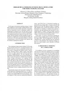
Behavioural Modelling and Simulation of Σ∆ Modulators Using Hardware Description Languages R. Castro-López1, F. V. Fernández1,2 F. Medeiro1,2 and A. Rodríguez-Vázquez1,2 1IMSE-CNM, Edif. CICA, Avda. Reina Mercedes s/n, E-41012 Sevilla, SPAIN Phone: +34 955056666, FAX: +34 955056686, e-mail:
[email protected] 2 Escuela Superior de Ingenieros, Isla de la Cartuja s/n, E-41092 Sevilla, SPAIN Phone: +34 954487378, FAX: +34 954487379 Abstract Behavioural simulation is the common alternative to the costly electrical simulation of Σ∆ modulators (Σ∆Ms). This paper explores the behavioural modelling and simulation of Σ∆Ms by using hardware description languages (HDLs) and commercial behavioural simulators, as an alternative to the common special-purpose behavioural simulators. A library of building blocks, where a HDL has been used to model a complete set of circuit non-idealities influencing the performance of Σ∆Ms, is introduced. Three alternatives for introducing Σ∆M topologies have been implemented. Experimental results of the simulation of a fourth-order 21-1 cascade multi-bit Σ∆M are given.
1. Introduction Oversampling converters have become very popular due to their ability to solve problems found in other architectures like the need for high-accuracy analogue antialiasing filtering and the large sensitivity to circuit imperfections and noisy environments [1],[2]. As for other electronic systems, a crucial step in the design process is the validation of the design by using some procedure that allows accurate emulation of the Σ∆M behaviour. Such a simulation step is used both in synthesis processes, in which CPU time consumption is a main feature to consider, and in verification processes, where high levels of accuracy are required. Thus, a main goal to face is the adoption of a proper simulation technique which must be both accurate and fast to efficiently analyse the performance of Σ∆Ms. The most accurate technique is transistor-level simulation. Unfortunately, though theoretically possible, electrical simulation of complex systems may become impractical. In particular, for Σ∆Ms, the extraction of their
1530-1591/03 $17.00 2003 IEEE
performance involves the analysis of a very large number of samples at the modulator output, which means a very long transient analysis: days or weeks of CPU time can be required to estimate the signal-to-noise ratio from the extracted layout of a typical Σ∆M [3],[4]. The use of macromodels instead of transistor-level descriptions simplifies the problem but simulation is still too slow, because the resulting system of differential equations must still be solved numerically. Another solution is mixed-signal (multi-level) simulation, in which analogue and digital parts are simulated separately but not independently. Macromodels or behavioural models are used for the analogue part. However, equations for the analogue part are still solved numerically, which makes extraction of Σ∆M performances too costly in CPU time. Event-driven behavioural simulation, which tries to bring the simulation of mixed-signal circuits closer to logic simulation, is a more efficient solution. In fact, it is the introduction of event-driven simulation techniques which makes the difference. This approach requires that the circuit can be partitioned into basic blocks with independent functionality. This implies that an instantaneous block output cannot be related to itself, that is, either there is no global feedback loop, or in case such loop exists there is a delay that avoids the instantaneous dependence. The eventdriven simulation of such circuits require appropriate behavioural models for all the blocks, in the form of explicit expressions relating the output variables with the input and internal state variables. A first approach to create such behavioural descriptions for event-driven simulation is the use of programming languages such as C. Several tools especially devoted to the behavioural simulation of Σ∆Ms using that approach have been reported [4]-[8]. The main differences among them are in the number of topologies/basic blocks included, the accuracy of the models used, the post-processing capabili-
ties and the friendliness of the user interface. A representative example is ASIDES [7], which is written in C language and, consequently, is very fast, which makes it very appropriate, not only for verification, but also for synthesis procedures based on iterative optimization. In contrast, ASIDES and the rest of special-purpose Σ∆ simulators are partially closed. They contain behavioural models for a particular set of blocks and are, in general, open to any architecture built by using such blocks. But the addition of new blocks and/or different behavioural models for an existing block, is restricted to the tool developers. Besides, neither simulation of modulators with different description levels for each block (e.g., behavioural, macromodel or transistor levels) nor simulation with other subsystems (digital or analogue) is feasible with special-purpose simulators. An alternative solution involves the use of the standardized HDLs, such as VHDL [9] and its analogue extension VHDL-AMS [10]. An important benefit derived from the use of these description languages is that HDL simulators are already included in many commercial design environments. In this way, Σ∆Ms modelled with VHDL can be simulated together with other VHDL-modelled blocks and even continuous-time descriptions of blocks, modelled using VHDL-AMS. Furthermore, blocks described at different levels of accuracy (extracted layout, transistor, macromodel or behavioural levels) can be combined into a single simulation. In this way, HDLs can overcome the drawback of special-purpose approaches mentioned above, without compromising speed. Consequently, designs can be easily exchanged thus reducing the integration and the entire development efforts. In addition, since HDLs have a wide range of descriptive capability to characterize Σ∆M performance non-idealities, accuracy is not compromised either. In this paper, we have used the VHDL language to model high-performance Σ∆Ms and all major non-idealities affecting the nominal behaviour of these systems. Among the imperfections considered, we include the modelling of the integrators’ settling error for both the integration and sampling phases, to our knowledge, only previously considered in [11]. Two mechanisms to create behavioural descriptions of Σ∆Ms (by directly writing the VHDL code and by using a schematic capture tool) are described. A third alternative for non-expert VHDL users has been developed. This alternative allows to describe Σ∆M topologies and analysis commands by using a very simple syntax; and the VHDL code is generated and the suitable behavioural simulations are executed automatically. The paper is organized as follows. Section 2 gives a general overview of the non-idealities considered in this work and how they have been modelled with VHDL. Afterwards,
Section 3 describes in detail the different techniques adopted to describe Σ∆Μ topologies. Section 4 shows simulation results of a Σ∆Μ. Concluding remarks are given in Section 5.
2. HDL modelling of Σ∆Μ building blocks The conceptual representation of a Σ∆Μ is shown in Figure 1. The output y is subtracted from the input signal, x, which has been sampled at a rate larger than the Nyquist frequency. The result, after passing through the discretetime filter, H(z), is the input to the quantizer. The simplest block to implement H(z) is a discrete-time integrator. In this way, the quantization power spectral density decreases in the low-frequency range due to a shaping function performed on the quantization error. The non-idealities degrading the behaviour of Σ∆Μs can be implemented separately by including imperfections in the behaviour of each building block: integrators, quantizers and D/A converters. X
+ −
H(z)
Y
I
Nbit
DAC
Figure 1. Basic structure of a Σ∆ modulator.
2.1. SC integrator The integrator is the fundamental block because its nonidealities largely affect the performance of Σ∆Μs. Figure 2 shows the generic SC integrator scheme considered herein. There are i branches connected to switching input voltage Vk1 and Vk2, and j branches of an integrator connected to its output during the sampling phase, switched to input levels Vnk2 during the previous integration phase. Cp is the paraCo φ C V11 1d 1 φ2 va V12 φ1 C φ2d p
V21 V22
Vi1 Vi2
φ1d C 2 φ 2 φ2d
φ2d
φ1
vo Cl
φ1d Cn1
Vn12 φ2d φ1d Cn2
φ1
φ1d C i φ 2
+
.. .
Vn22 φ2d .. .
Vnj2
φ2
φ2 φ1
φ1d Cnj φ2 φ2d
+
φ1
.. .
φ1
Figure 2. SC integrator model.
sitic capacitor associated to the integrator summation node, Cl is the capacitive load and Co is the integration capacitor. A complete set of non-idealities have been modelled in VHDL: thermal noise, finite and non-linear dc gain, output range, opamp slew-rate and dynamics, capacitor non-linearity and mismatch, and switch resistance [2]. The complete integrator model follows the iterative procedure shown in the flow graph of Figure 3. During the sampling phase, the final value of the voltages stored in the input capacitors are calculated considering the values of these and the ON resistance of the switches. The input equivalent thermal noise of the integrator is calculated and added to the sampled voltage. Settling errors are then evaluated by following the analysis in [11]. This error basically depends on the amplifier dynamics, the capacitance involved, and the amount of charge distributed. It may result from a combination of both slew-rate limited and linear transient responses. During the integration phase, an iterative procedure is started to calculate the integrator output voltage, including the effects of the finite and non-linear opamp gain, the non-linear capacitors, transient response and the output range limitation [2],[11]. Whereas most integrator models limit the opamp dynamics to the integration phase, introducing these effects also in the sampling phase may become important, especially for high-speed applications. The implementation of the settling error model in VHDL poses a major problem because the calculation of the opamp input and output voltages involves knowing the voltage stored during the previous phase in the sampling capacitors of the following integrator, for Σ∆Μs of order larger than 1. Actually, the value of these voltages are parameters of the integrator settling model. A possible
NO
Sampling phase? YES
additional ports
Figure 4. Increase in the number of input ports of a 2-input integrator to enable dynamic external parameters. solution is to accommodate such parameters in the socalled ports of a block's model in VHDL. The problem is that these ports can only have fixed values during a simulation. To solve this problem, those ports connected to dynamic external parameters, are transformed into input ports, thus increasing the number of input ports of the integrators, as depicted in Figure 4.
2.2. Quantizers and D/A converters Single-bit architectures incorporate a simple comparator to perform the internal quantization. A simple D/A converter is then used in the feedback loop, which does not introduce any non-linearity error. The transfer curve of a comparator showing hysteresis and offset is depicted in Figure 5. In addition, some comparators also exhibit a hysteresis of random nature. Multi-bit modulators are especially affected by the nonlinearity error of the D/A conversion. For multi-bit D/A converters, characterized by an offset off, a gain γ, and an integral non-linearity INL, the converter input is passed through an ideal D/A converter. The result goes through a non-linear block with a third-order non-linearity and a gain block. Finally, the offset error is added [2], as it is depicted in Figure 6. An analogous scheme is used for multi-bit quantizers.
Opamp DC-gain DC-gain finite and non-linear
V max
S/H dynamics
TS v 1' = v 1 1 – exp – ----------- 2 RC Calc. of equivalent thermal noise
Calculation of sampled voltage
∆
Non-linear Capacitors
YES
Sampling transient
v
o
> OS ?
v = ± OS o
NO
END
Convergence?
b
NO
x Calculation of output voltage
Figure 3. Complete integrator model.
vi
Figure 5. Transfer curve of a comparator with hysteresis.
New DC-gain
YES
v off h
V min
Integration transient
+
vo
Ideal DAC
xa
Φ
wa
γ
+
ya
off Figure 6. Behavioural model of DA converters.
3. HDL modelling of Σ∆Μ architectures By making use of the building blocks of the previous section, a Σ∆M can be described in VHDL following three different procedures. The first procedure consists in describing the Σ∆M model through VHDL instances [9]. In principle, the user should perfectly know the number of parameters and inputs of every building block, including the extra ports which correspond to voltages of the sampling capacitors, as explained in Section 2.1. To avoid this extra burden, the user has just to introduce the VHDL code of the modulator architecture (with no additional input ports for the SC integrators) and a conversion program automatically traces circuit connectivity and generates a correct VHDL code with all extra information. An excerpt of the VHDL code for a fourth-order 2-1-1 cascade multibit Σ∆M, whose schematic is depicted in Figure 7, is shown in Figure 8(a). As an example of the operation of the conversion program above, the connectivity of integrators int2 and int3 through node oi2 is traced and the VHDL code in Figure 8(b) is automatically generated. As shown, three additional input ports (Xvcn1, Xvcn2 and Xvcn3) are generated at integrator int2 to handle the voltage stored in the sampling capacitors of integrator int3. A more user-friendly alternative is the use of a schematic capture tool. By using pre-defined symbols for each building block, it is possible to build a Σ∆M using a commercial tool. Also in this case, the user does not have to pay special attention to the connection of external dynamic parameters to input ports of the integrators. The same program above is used to properly modify the VHDL code generated from the schematic capture tool. An example of this alternative is the description of the Σ∆M of Figure 7 with Mentor Graphics’s HDL Designer®, as it is illustrated in Figure 9, where, as it can be noticed, integrators’ additional input ports do not need to be drawn. X
g
-
int1 1
g ' 1
g
oi1 -
int2
E1
oi2
2
A third alternative has been developed addressing those users with little experience in VHDL. In this case, the user just introduces the Σ∆Μ topology and some basic analysis commands using a very simple syntax, similar to the ASIDES tool [2],[7]. An important feature of the implemented tool, called VSIDES, is that the user does not have to know that SC integrators need additional inputs as explained in Section 2.1. When VSIDES generates the VHDL code, it automatically creates those ports. Once the correct behavioural description file has been generated, VSIDES automatically launches the appropriate simulations in the behavioural simulator. A flow diagram of VSIDES is shown in Figure 10. The VSIDES netlist of the 2-1-1 cascade multi-bit Σ∆Μ is shown in Figure 11.
(a)
int2 : integrador2 GENERIC MAP ( INT_TYPE => TRUE, osp => 4.0e+00, osn => -4.0e+00, Peso1 => 2.5e-01, Peso2 => 2.5e-01, ...) PORT MAP ( Reset => Reset, clock => clock, Xin11 => oi1, Xin12 => out1fb, Xin21 => oi1, Xin22 => gnd, Xout => oi2); int3 : integrador3 GENERIC MAP ( INT_TYPE => TRUE, osp => 5.0e+00, osn => -5.0e+00, Peso1 => 3.75e-01, Peso2 => 3.75e-01, ...) PORT MAP ( Reset => Reset, clock => clock Xin11 => oi2, Xin12 => gnd, Xin21 => oi2, Xin22 => out1fb, Xin31 => oi2, Xin32 => out2fb, Xout => oi3);
(b)
int2 : integrador2 GENERIC MAP ( INT_TYPE => TRUE, osp => 4.0e+00, osn => -4.0e+00, Peso1 => 2.5e-01, Peso2 => 2.5e-01, ...) PORT MAP ( Reset => Reset, clock => clock, Xin11 => oi1, Xin12 => out1fb, Xin21 => oi1, Xin22 => gnd, Xout => oi2, Xvcn1 => int3_vcn1, Xvcn2 => int3_vcn2, Xvcn3 => int3_vcn3); int3 : integrador3 GENERIC MAP ( INT_TYPE => TRUE, osp => 5.0e+00, osn => -5.0e+00, Peso1 => 3.75e-01, Peso2 => 3.75e-01, ...) PORT MAP ( Reset => Reset, clock => clock Xin11 => oi2, Xin12 => gnd, Xin21 => oi2, Xin22 => out1fb, Xin31 => oi2, Xin32 => out2fb, Xout => oi3 Xvcn1 => int4_vcn1, Xvcn2 => int4_vcn2, Xvcn3 => int4_vcn3);
Y1
g ' 2
-
g
int3
3 g ' 3 g '' 3
E2
oi3
Y2 DAC
-
g 4 g ' 4 g '' 4
int4
oi4 ED
E3
Cancellation Logic
DAC Y
3-bit
ADC
Y3
b
b
3-bit
DAC
Figure 7. Fourth-order 2-1-1 cascade multibit Σ∆ modulator.
Figure 8. Excerpt of the VHDL code for the fourth-order Σ∆Μ (a) without and (b) with additional input ports.
Object properties window of the integrator int3
Figure 9. Snapshot of a 2-1-1 cascade multi-bit Σ∆ modulator drawn with HDL Designer®.
VHDL functions
Add ports to SC integrators Automated Process
Netlist Description · control sentences · input source · Σ∆Μ topology · building block models · parameter definitions
VSIDES syntax
Create VHDL file
VHDL commercial simulator
Output post-processing
End
Figure 10. VSIDES operation flow. A number of post processing capabilities have also been implemented as VHDL functions to enable full exploitation of the behavioural simulation results: output spectrum, SNDR as functions of the input level or frequency, in-band error power, effective resolution, Monte Carlo analysis, parametric analysis (any characteristic with some non-ideality as variable parameter), etc. For parametric analysis, the variable parameters are handled like the sampling capacitor voltages: by introducing additional input ports.
4. Experimental results In this section, the HDL modelling of non-idealities influencing the performance of Σ∆Μs presented herein above, will be illustrated through several simulations of the 2-1-1 cascade multibit Σ∆Μ in Figure 7. This modulator is
#4th-order cascade 2-1-1 SDM supply 2 -2 2 -2; nsamples 65536 16; output snr Xout; clock frec=35.2e6; #INPUT SOURCE source vin Xin 1.0 0.275e6; #FIRST STAGE int1 oi1 Xin out1 0.25; int2 oi2 oi1 gnd 0.25 oi1 out1 0.25; comparator out1 oi2; #SECOND STAGE comparator out2 oi3; int3 oi3 oi2 gnd 0.375 oi2 out1 0.375 oi2 out2 0.25; #THIRD STAGE quantz out3 oi4 3; dac conv3 out3fb out3 3; int4 oi4 oi3 gnd 2 oi3 out2 1 oi3 out3fb 1;
Figure 11. A 2-1-1 cascade multi-bit Σ∆ modulator described with VSIDES (cancellation logic not shown). especially indicated in medium/high-frequency applications. Figure 12 shows, via a Monte-Carlo analysis, the effect of mismatching in the capacitor ratios implementing the integrator gains. This type of architecture is especially sensitive to such non-ideality because its operation is based on the cancellation of the first- and second-stage quantization noise, using digital circuitry. The coefficients included in this circuitry must fulfil a relationship with the analogue weights, affected by mismatching. Architectural model compilation took 7.5s. and the simulation of this first experiment took 3.7s. for each simulation of the MonteCarlo analysis1. 1 All the reported simulations were performed in a SunFire 3800 platform @ 750 MHz.
5. Conclusions
Nominal analysis Monte-Carlo runs
80
SNR (dB)
70 60 50 40 30 -40
-35
-30
-25
-20 -15 -10 Frequency (Hz)
-5
0
5
Figure 12. Capacitor mismatching effect. It is also interesting to evaluate which is the accuracy of the behavioural simulation and how it compares with a conventional electrical simulator. The power spectral density (PSD) plots in Figure 13 were obtained from four different sources. First, it was computed, from 65536 samples, by simulating the VHDL-modelled Σ∆Μ using Mentor Graphics’ Advance-MS®. Architectural model compilation took 7.5s. and simulation time took 3.6s. ASIDES [2], [7] took 2.3s. to get the same PSD with the same number of samples. The results are obviously identical because the same behavioural models were used for both VHDL simulation and ASIDES. Accuracy of these simulations can be verified by comparison with the experimental results (shown in the same figure) obtained from a chip prototype. A different signal frequency has been chosen for better visualization. Figure 13 also shows the PSD obtained with HSPICE. The simulation took 5 days of CPU time to get only 8192 samples. It can be observed that HSPICE computes a lower error power because thermal noise cannot be included in the transient simulation. Measured HSPICE VHDL & AdvanceMS
-60
PSD (dB/Hz)
-80 -100 -120 -140 -160 -180 104
105
106 Frequency (Hz)
107
Figure 13. Simulated and measured PSD.
Hardware description languages (HDLs) together with commercial behavioural simulators are efficient resources to perform the validation of Σ∆Μs. The main advantage of HDLs, when compared with transistor-level, and even macromodel descriptions, is the drastic reduction of the simulation time (seconds compared with hours or days). Moreover, the use of a mixed-signal behavioural simulator like Mentor Graphics’ Advance-MS®, allows combining Σ∆Μs with VHDL descriptions of digital blocks or VHDLAMS descriptions of other analogue blocks (even a lowerlevel VHDL-AMS description of any block of the Σ∆Μ can be used). The capability to simulate Σ∆Μs within more complex systems and the integration into commercial design environments makes HDLs a profitable alternative to the special-purpose Σ∆ behavioural simulators.
References [1] J. Candy and G.C. Temes, “Oversampling Methods for A/D and D/A Conversion,” in Oversampling Σ∆ converters, pp. 125, IEEE Press, 1992. [2] F. Medeiro, B. Pérez-Verdú and A. Rodríguez-Vázquez, TopDown Design of High-Performance Sigma-Delta Modulators. Kluwer Academic Publishers, Boston, 1999. [3] V. F. Dias, V. Liberali and F. Maloberti: “Design Tools for Oversampling Data Converters: Needs and Solutions”, Microelectronics Journal, Vol. 23, pp. 641-650, 1992. [4] C. H. Wolff and L. Carley: “Simulation of ∆-Σ Modulators Using Behavioural Models”, Proc. IEEE Int. Symp. Circuits and Systems, pp. 376-379, 1990. [5] V. Liberali, V.F. Dias, M. Ciapponi and F. Maloberti, “TOSCA: a Simulator for Switched-capacitor Noise-shaping A/D Converters,” IEEE Trans. Computer-Aided Design, Vol. 12, No. 9, pp. 1376-1386, Sept. 1993. [6] A. Opal: “Sampled Data Simulation of Linear and Nonlinear Circuits”, IEEE Trans. on Computer-Aided Design, Vol. 15, pp. 295-306, March 1996. [7] F. Medeiro, B. Pérez-Verdú, A. Rodríguez-Vázquez and J.L. Huertas “A Vertically Integrated Tool for Automated Design of Σ∆ Modulators” IEEE J.Solid-State Circuits, pp. 762-777, July 1995. [8] K. Francken, P. Vancorenland and G. Gielen, “DAISY: a Simulation-based High-level Synthesis Tool for ∆Σ Modulators,” Proc. IEEE/ACM Int. Conf. Computer-Aided Design, pp. 188-192, 2000. [9] IEEE VHDL Language Reference Manual, IEEE Std 10762002. [10] IEEE VHDL 1076.1 Language Reference Manual, IEEE Std 1076.1-1999. [11] R del Río, F. Medeiro, B. Pérez-Verdú and A RodríguezVázquez “Reliable Analysis of Settling Errors in SC Integrators: Application to Σ∆ Modulators,” IEE Electronics Letters, pp. 503-504, Vol. 36 Iss. 6, March 2000.