J Grid Computing DOI 10.1007/s10723-010-9175-7
Belle-DIRAC Setup for Using Amazon Elastic Compute Cloud Providing Homogeneous Access to Heterogeneous Computing Resources Ricardo Graciani Diaz · Adria Casajus Ramo · Ana Carmona Agüero · Thomas Fifield · Martin Sevior
Received: 7 June 2010 / Accepted: 23 November 2010 © Springer Science+Business Media B.V. 2011
Abstract The Distributed Infrastructure with Remote Agent Control (DIRAC) software framework allows a user community to manage computing activities in a distributed environment. DIRAC has been developed within the Large Hadron Collider Beauty (LHCb) collaboration. After successful usage over several years, it is the final solution adopted by the experiment. The Belle experiment at the Japanese High Energy Accelerator Research Organization (KEK) has the purpose of studying matter/anti-matter asymmetries using B mesons. During its lifetime, Belle detector has collected about 5,000 terabytes of real and simulated data. The analysis of this data requires an enormous amount of computing intensive Monte Carlo simulation. The Belle II experiment, which recently published its technical design report, will produce 50 times more data. Therefore it is interested to determine if commercial computing clouds can reduce the total cost of the experiment’s computing solution. This paper describes the setup prepared to evaluate the
R. Graciani Diaz (B) · A. Casajus Ramo · A. Carmona Agüero University of Barcelona, Barcelona, Spain e-mail:
[email protected] T. Fifield · M. Sevior University of Melbourne, Melbourne, Victoria, Australia
performance and cost of this approach using real 2010 simulation tasks of the Belle experiment. The setup has been developed using DIRAC as the overall management tool to control both the tasks to be executed and the deployment of virtual machines using the Amazon Elastic Compute Cloud as service provider. At the same time, DIRAC is also used to monitor the execution, collect the necessary statistical data, and finally upload the results of the simulation to Belle resources on the Grid. The results of a first test using over 2000 days of cpu time show that over 90% efficiency in the use of the resources can easily be achieved. Keywords Grid · Cloud · Integration · Interoperability · DIRAC
1 Introduction The DIRAC project [1] started in 2002 as a software tool able to manage LHCb (see [2] and [3]) Monte Carlo simulation in an efficient manner. At this time it was already clear that a distributed computing solution would be needed. LHCb Monte Carlo simulation is a computing intensive application that requires many hours in order to produce at most few hundred megabytes (MB) of output data. Computing resources were available at a large number of sites while significant storage capacity was limited to few sites.
R. Graciani Diaz et al.
At that time, Grid middleware was in a very early stage of development and most of the resources were only available to LHCb via direct submission to the Local Resource Management Systems (LRMS) from dedicated front-end machines. DIRAC [4] was designed to make use of all of these resources (Grid and non-Grid) in a uniform way. Applications were shielded as much as possible from the mechanism used to get them running on a particular Worker Node (WN) at a given site. Similarly, production managers (the end-users of the system at the time) were shielded from the different mechanisms used to get access to the resources. Currently, DIRAC handles all computing activities described in the LHCb Computing Model [5]. DIRAC manages data distribution from the LHCb detector to mass storage at CERN, CERN Advance STORage (CASTOR [6]), and from there to all LHCb Tier1s,1 based on the site share of the data [7]. DIRAC also takes care of all required processing steps to make this data available for physics studies: calibration, reconstruction, pre-selection, merging, etc. After the system has been properly configured, all the jobs necessary to complete these tasks are automatically created by DIRAC agents as the data from the detector is successfully transferred to its destination Tier1. Following this, DIRAC takes care of the jobs by locating appropriate computing resources to execute them. It monitors the execution, collects and uploads the results to the proper destination, and finally accounts for the usage of the resources. DIRAC simultaneously controls large scale activities to produce Monte Carlo simulated data and the execution of analysis algorithms by the physicists of the collaboration. Belle is an experiment [8] designed to research charge-parity violation, rare decays, search for exotic particles and undertake precision measurements of bottom and charm mesons and the tau lepton. Belle started taking data in 1999 and has accumulated an integrated luminosity of approximately 1 ab−1 during its ten years of operation [9]. 1 LHCb makes use of six Tier1 Grid resource centers (CNAF, GRIDKA, IN2P3, NIKHEF-SARA, PIC and RAL) that provide both computing power and long term storage to the experiment.
It is supported by a centralized computing facility at KEK, where almost all data processing, Monte Carlo simulation and physics analysis is performed. However, Belle II—an upgrade of the Belle detector to probe physics beyond the standard model—will collect 50 times more data. A Grid based approach with resources at member institutes is being designed to facilitate this. With this in mind, recently Belle has been working to run Monte Carlo production on the EGEE/EGI Grid. Currently, custom scripts based on low-level middleware tools are used to install software, execute jobs and retrieve output. The Belle II computing model foresees that Monte Carlo simulations are done using real data as a source of background events, making use of run-by-run conditions and integrated luminosity [10]. This results in large peaks of computing power needs at the end of each data taking period when the simulations corresponding to the recently taken data proceed. In order to provide enough resources to absorb these peaks, Belle computing centers need to have an installed capacity that exceeds the average yearly needs with the corresponding associated extra costs. An earlier investigation of the use of on-demand computing to cover these peaks is presented in [11]. Following the success of these initial studies a large scale case study has been planned. The case study will use real Belle simulation jobs from the 2010 Belle campaign, with the aim to estimate under real conditions the reliability and cost of the method. This paper describes the setup prepared for this case study using the DIRAC framework for distributed computing. The setup should allow the processing—in an efficient manner—of more than 100 million simulated Belle collisions on cloud resources. The setup should serve two different aims: evaluating the cost associated with the use of cloud resources, and providing a baseline solution for Belle II computing integrating different types of resources. The paper is organized as follows: Section 2 includes a review of the case study and some related work, Section 3 then presents an overview of the DIRAC framework with special emphasis on those aspects more relevant for the setup being discussed. Section 4 describes the proposed setup
Belle-DIRAC Setup for Amazon EC2
using standard DIRAC components as well as newly developed ones, then a discussion of the weak and strong points of the proposed solution follows in Section 5. The usage of the proposed setup to execute a sizable amount of Belle simulations on the Amazon Elastic Compute Cloud (EC2) is reported on Section 6. Finally, a brief summary is presented in Section 7 together with an outlook of future developments.
2 Review of the Case Study The aim of the setup and the associated case study is to prove the efficient use of cloud resources for this particular task. At the same time, the cost associated to the contribution from commercial cloud resources must be determined. Additionally, the proposed setup solution must be able to integrate other computing resources, like Grids or local clusters, and scale up to expected needs of Belle II experiment. The Belle Monte Carlo simulation task is divided into individual sub-tasks closely following the data taking of the experiment. Each individual sub-task corresponds to a detector run2 and thus there is a huge dispersion in the cpu time and output data requirements, depending on the duration and conditions of the corresponding run. The input for the simulation is taken from the official sets of scripts and input data files provided by the computing group of the collaboration. They have to be executed on cloud WNs. And, at the end of the execution, the simulated data and log files must be transferred to Belle Grid Storage Elements (SEs) and File Catalog (FC). The setup should provide enough flexibility to change the number of virtual machine instances that are running. At the same time, it must record information about the running jobs and instances, and have a simple interface for monitoring and operation.
2 A run is the collision data registered by a detector in an uninterrupted manner with almost identical conditions, its duration and the accumulated data may vary by several orders of magnitude.
Manpower for these developments is limited. Therefore, reusing an existing solution from one of the LHC experiments [12–16] that are routinely making use of thousands of CPUs in the EGEE/EGI infrastructure is the preferred approach. In this way, development can concentrate on the aspects related to the access of cloud resource. The accounting and monitoring to evaluate the case study will be provided in the existing tool. The DIRAC software framework developed and used by the LHCb collaboration for their distributed computing has been chosen. DIRAC is a well tested tool that has been in production for many years. It is able to scale to many tens of thousands tasks per day and integrates over 100 Grid resource provider sites within LHCb. From the beginning, it was designed to integrate Grid and non-Grid resources providing a homogeneous access layer to heterogenous resources. DIRAC has also proven its flexibility when integrating all the LHCb computing activities in a single system. Nevertheless, DIRAC remains a generic tool only loosely coupled to LHCb. This enables to design a flexible setup that integrates all the resources needed for Belle II. 2.1 Related Work The interoperability between Grids and clouds has been under investigation for some time. The beginnings of the research can be seen in the work of adding the ability to make batch systems “dynamic”—that is, adding and removing (often virtualised) Worker Nodes from a batch system queue based on certain events [17–22]. This has resulted in such modern projects as INFN’s Worker Node on Demand [23], which deploys virtualized resources at the WLCG Tier1 in Italy. This methodology, aiming to make computing resources “elastic” matches well with cloud computing. According to a recent StratusLab survey [24], most administrators who responded were already using cloud or virtualization technologies or planning to deploy them in the next 12 months. EGEE, the peak general purpose Grid infrastructure in Europe at the time, itself acknowledged the potential of cloud computing in
R. Graciani Diaz et al.
their 2008 study [25], concluding that “a roadmap should be defined to include cloud technology in current e-Infrastructures ...”. As a result, currently there are several EU-funded projects working on various aspects of cloud-Grid integration, and providing simplified access cloud paradigm to the community: –
–
–
Stratuslab [26] is tasked to “integrate cloud and virtualization technologies and services within Grid sites and enrich existing computing infrastructures with “Infrastructure as a Service (IaaS)” provisioning paradigms.” Venus-C [27] is “focused on developing and deploying a Cloud Computing service for research and industry communities in Europe by offering an industrial-quality service-oriented platform”. RESEVOIR [28] will “provide a foundation for a service-based online economy, where— using virtualization technologies—resources and services are transparently provisioned and managed on an on-demand basis...”
However, despite this large amount of work on the infrastructure angle, little work has been completed from the Virtual-Organisation side. Notable projects here include clobi [29] which provides a cloud backend to Ganga [30] for the ATLAS experiment [14].
3 DIRAC Overview The DIRAC software framework for distributed computing is described in more detail in [1]. A brief discussion of the DIRAC systems relevant for the purpose of the setup described in this work is made in the following subsections. 3.1 Secure Transport DIRAC components use a custom protocol for client-server communication. The DIRAC SEcure Transport (DISET) protocol [31] provides a uniform way for building distributed applications that are connected securely using X509 certificates [32] and Grid proxies [33] for authentication. OpenSSL [34] is used by DISET to handle
the cpu-intensive operations such as encryption and authentication. Additionally, DISET provides remote process command (RPC) and data transfer capabilities together with configurable authorization rules for authenticated clients (including user and group identity). DISET framework makes the authenticated identity available to the server method. When appropriate, methods can use this information for finer grained rules, like providing plain users access only to the information about his/her own tasks in the system while giving full access to administrative users. DIRAC components on the cloud will also use the DISET protocol for communication with other parts of the system to ensure the security of the setup. 3.2 Configuration The configuration system is the set of DIRAC components that allows the rest of the DIRAC framework, including the configuration system itself, to locate each other using Service URLs (SURLs). At the same time, it allows global default values for configuration parameters of any DIRAC component to be set. DIRAC configuration options are organized in a tree structure where each node in the tree is a section that contains options and/or other sections. Each option gets an associated value that can be retrieved with a single call inside the DIRAC python code. For each DIRAC installation there is a single configuration Master server that is the only place where the default configuration data can be edited. Additionally, for improved redundancy, a number of configuration Slave servers can be setup. The slave servers synchronize with the Master and request the registration of their SURL in the default configuration data of the master to make themselves available as alternative configuration servers. On the client side only the SURL of one of these configuration servers (kept in a default configuration file loaded at start of the execution) is necessary. A configuration client thread downloads the full configuration data and makes it available in a local cache. If necessary, the configuration thread updates the data for one of
Belle-DIRAC Setup for Amazon EC2
the servers at regular intervals. This is totally transparent for the component code accessing the configuration data. Using the DIRAC configuration system ensures that components executing on the cloud can access at any time the most up-to-date global default values, i.e., they can be remotely reconfigured if necessary.
user task, it just means that some additional pilots are submitted. And secondly, it provides a well defined execution environment to the user task. When using cloud resources pilots are replaced by the instantiation of a virtual machine but the same pull scheduling is preserved.
3.3 Workload Management
Only a limited set of components from the DIRAC Data Management System (DMS) are relevant for the proposed setup. They are the following:
The Workload Management System (WMS) is one of the central pieces of the DIRAC framework for distributed computing. It is based on a pull scheduling paradigm with late binding of resources to payload. In a distributed system it is not realistic to assume that any central component is able to know and predict at any moment in time the current and future availability of computing resources. Therefore, the classical push scheduling paradigm is unreliable and inefficient in distributed scenarios. The way DIRAC implements the pull scheduling is as follows: – –
–
–
–
A central WMS server keeps the list of pending tasks organized in TaskQueues. Each TaskQueue contains tasks with identical execution requirements, e.g., CPU time requested by the user, the required platforms to execute, or the identity of the submitter. Dedicated DIRAC agents attempt to get hold of appropriate computing resources for each TaskQueue. This is done via pilot jobs, see [35], both when using Grid resources or a local batch system. Once a pilot manages to execute at a certain resource, a WN, it checks the environment and requests a pending task from the central server. After the execution of the task is completed, the pilot uploads the results, reevaluates the computing resources available and requests a new pending task if appropriate.
Using this approach, DIRAC shields the users task in two different ways. Firstly, DIRAC takes care of input and output sandboxes for the user task as well as for the delivery of any necessary software. Any problem in the propagation of the pilot until it reaches the WN does not affect the
3.4 Data Management
–
–
–
Storage Element: DIRAC provides a secure remote interface to the local storage of a server via the Storage Element service using the DISET. This Storage Element does not attempt to do any space management, except for refusing new incoming data once space gets full. It is mostly used for hosting input/output sandboxes for WMS tasks. The use of the DIRAC SE in the context this setup is described in Section 4. File Catalog: DIRAC provides a Replica File Catalog server implementation including access control and trivial metadata like file size, checksum or creation timestamp. Replica Manager: this is a client side DIRAC component that encapsulates interactions with SEs and FCs, i.e., file upload and registration or file replication. Using this component and the appropriate middleware plugins, access to DIRAC and gLite [36] storage systems and file catalogs, providing an abstraction layer that makes it transparent for any other DIRAC component to make use of Grid and non-Grid storage resources.
As in the case of the WMS, DMS components try to fill the gap between the Grid world and the non-Grid world, allowing the use of middleware components when the scale of the problem requires it, but at the same time giving the chance to build the same functionality with its own components assuring much lighter requirements, higher portability and full compatibility. This possibility is used in Section 4 to improve the efficiency of the proposed setup.
R. Graciani Diaz et al.
3.5 Web Portal and Other Components DIRAC includes the possibility to monitor and control the activity of the system and its behaviour via a dedicated web portal, see [37]. Connections to the portal are encrypted and the user is authenticated by the user’s Grid certificate that it is imported to the browser. At any time, the authenticated user can select the privileges associated to one of the groups the user belongs to in DIRAC. The browser on one side and the portal on the other recognizes the selected group and varies the displayed menus, selection panels and available actions accordingly. This identity is forwarded by the DIRAC components which execute behind the web server. The appropriate DIRAC server then applies the authorization rules as needed (see Section 3.1). In the setup presented in Section 4 the execution of the study case is followed using the portal interface to DIRAC. Other DIRAC components used in the proposed setup are: –
–
–
Accounting: provides a persistent backend and report generation tool for the information relative to the different actions controlled by DIRAC, in this case: user task execution and output data upload and registration. User Interface: allows the person in charge of the execution to submit the Tasks and retrieve their outputs. Job Agent and Job Wrapper: the first one matches a user task from the central TaskQueue and the second one supervises the correct execution of the user Task on the computing resource, reports periodically the activity and takes actions in case of abnormal behaviour or conditions.
4 A DIRAC Setup for Running on a Cloud The use of Virtual Machines (VMs) as WNs has not been done before in the DIRAC framework. Therefore, the first thing to be done was designing the appropriate components for it. These new
components, developed specifically for this setup, are described in some detail in the next subsection. The final setup implemented for the exercise is presented afterwards. 4.1 DIRAC Interface to Virtual Machines In its origin, DIRAC had only a direct interface to local computing resources like a LRMS or the local PC via a ComputeElement (CE) module. It was quickly noticed that in a distributed environment this approach was not enough and the notion of pilot job was introduced. A DIRAC pilot job is a resource reservation job that runs a DIRAC Job Agent at a computing resource appropriate for the execution of the user payloads. Only when a DIRAC Job Agent is already running in the WN, is a user task matched, extracted from its TaskQueue and executed. When using Grid resources, DIRAC uses a PilotScheduler Agent together with middleware specific dispatcher (called PilotDirector) to populate Grid WNs with DIRAC pilot jobs following the demand of waiting tasks. Only small changes are required for making use of VMs. The basic idea is to make use of VMs instead of pilots as container for the Job Agent. To integrate on demand VMs as computing resources in DIRAC four main functional pieces have been identified. Apart from these newly developed components to deal with the new resource provider, no further modifications have been done with respect to a standard DIRAC setup. 4.1.1 Virtual Machine This is no more than a Linux based VM image, compatible with the service provider requirements, where a standard DIRAC installation has been done. The user tasks are matched and executed by a DIRAC Job Agent (identical to one being executed on a Grid WN described in Section 3.3). In parallel with this, the VMMonitor Agent (see below) takes care of uploading output data to its final destination.
Belle-DIRAC Setup for Amazon EC2
4.1.2 VirtualMachineManager Server and Database This is a new DIRAC central component that takes care of the persistency of the information relative to VMs. The database (DB) and its associated server, the VMManager, provide the possibility to register new images as they are created. Before being used, the description of the new images must be included in the DIRAC configuration, defining the following parameters: flavor: uniqueID: minCPU:
maxVMs: minLoad:
requirements:
the resource provider for which the Image is valid, i.e., Amazon. unique identifier of the Image as returned by the cloud provider. minimum amount of cpu time required by waiting task necessary to request a new VM. maximum number of VMs to run simultaneously. minimum load required on the VM, when it drops below this threshold for certain period of time the VM is halted. dictionary defining the computing capabilities of the Image, used to match tasks.
The methods available in the VMManager allow: registering a new VM of a known Image type, as preliminary step before submitting the request for a new VM; declaring a VM submitted while inserting the unique identifier of the VM instance provided by the backend (these methods are invoked by the VMScheduler, see below); declaring the VM running; receiving periodic heart beats with the load and some report on the activity; and declaring the VM is halting (these methods are called by the VMMonitor, see below). All the information arriving through these methods is persisted in the DB that keeps the current status of all Images and VM instances. The DB also keeps the history of the VMs as reported through their heart beats. The VMManager periodically checks for stalled VMs that have failed to report back their activity through the heart beat mechanism for an extended period.
4.1.3 VirtualMachineMonitor Agent This new component executes on the VM. It is started immediately after the startup of the operating system and its first action is to declare the VM running state to the VMManager. In case of error in the connection or if any abnormal condition reported back by the Manager, the VM is halted. After this point, the VMMonitor periodically monitors the cpu load of the VM, the number of executed tasks and the amount of output data uploaded. This information is reported to the VMManager in heart beats from the VM. Next, the VMMonitor asynchronously uploads the output data produced by the tasks executed to the required final destination. In this way, the VM is immediately available for new executions reducing idle time. Finally, when the VMMonitor detects that the load of the VM has dropped below a certain configurable threshold and if there are no pending transfers on going, the VM is halted. When sending the heart beats, the VMMonitor can receive commands from the VMManager. Accepted commands are: “stop”, wait for the end of the execution of current task and halt; “resume”, reverse the previous command; and “halt”, immediately halt the VM. In this way, the VMManager is able to reduce the number of running VMs in a controlled manner, or immediately, if need should be. 4.1.4 VirtualMachineScheduler Agent This component requests the execution of new VMs to the cloud backend as necessary. It monitors the central TaskQueues and matches pending tasks to the capabilities of the defined images. It checks the maximum number of VMs to execute and the current number of running VMs. With a very simple logic, if there is enough cpu time required by pending tasks and if the maximum number of VM running limit is not reached, the execution of a new VM is requested to the backend. This logic can be more elaborate if necessary. For instance, if several providers are defined that make available VMs with different hardware and the most efficient choice is to be found. For
R. Graciani Diaz et al.
the purpose of the present study case, the choice has been reduced to a single option. The HighCPU Extra Large Virtual Machine from Amazon EC2 was preselected as the most efficient for the simulation task. A resource specific VMDirector module has been coded to submit the requests to Amazon EC2. For other resource providers, analogous VMDirector modules can be implemented. This component takes the role of DIRAC PilotDirector (see [35]) used to interface DIRAC with Grid computing resources. Instead of submitting a pilot that installs DIRAC and executes a Job Agent on a WN, a full VM with DIRAC preinstalled configured to execute an endless loop of the Job and the VMMonitor Agents is requested. The necessary details for the billing must also be defined in the DIRAC configuration for each Image. However instead of placing them on the central configuration server (available to any user of the system) it is kept in a configuration file local to the VirtualMachineScheduler.
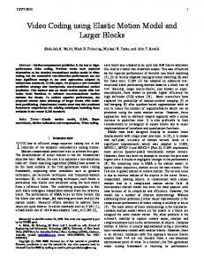
represented by a human figure, the DIRAC central servers running at the University of Barcelona (UB) called Barcelona, the DIRAC VM resources running on Amazon EC2, and the gLite File Catalog and Storage Elements running on the EGEE infrastructure. For better portability of the setup, all DIRAC components, including those executing at UB, use virtual machine technologies. Briefly, the functionality of the high level blocks depicted in Fig. 1 is (Each of these blocks is described in detail in the following subsections): the user submits the request of the Belle Monte Carlo simulation in the form of DIRAC computing tasks (or jobs) and monitors the execution from a DIRAC user interface; the central DIRAC installation receives the request and orchestrates the submission of VMs to the Amazon cloud as necessary; VMs executing on the cloud take care of the actual execution of the simulation requests; and, finally, Storage resources on the EGEE Grid where the output of the simulation are uploaded and registered.
4.2 The Implemented Setup 4.2.1 DIRAC Central Servers and Agents An architectural view of the implemented solution to use Amazon EC2 resources for Belle simulations is shown in Fig. 1. At the top level one can identify four main components: the user interface
They are responsible for receiving the user requests and taking appropriate actions to get them executed in the most adequate and efficient
Fig. 1 Schematic architectural description of the proposed DIRAC setup for executing Belle simulation tasks on Amazon EC2
Belle-DIRAC Setup for Amazon EC2
manner. For this particular case study, there is one configuration server master, one web portal, WMS servers and agents (including the VM Scheduler and Manager described in Section 3), and accounting servers. All these components together with their associated database back-ends are running on a single VM with 1,024 MB of memory and one virtual processor assigned. If the setup is to become a production setup, one just needs to move the VM wherever the Belle collaboration wants to place it and to assign to it the necessary resources for the full scale of their activity.
used for the task match making. The name of the image, its associated requirements and the cloud back-end for which it has been prepared are declared in the DIRAC Configuration. The boot sequence of one of these execution VMs is the following: –
–
4.2.2 Amazon Virtual Machines Two different types of VMs have been used: a storage VM and an execution VM. In order to reduce delays in the execution due to network latency, one permanently running storage VM has been used as temporary buffer for the input data. One DIRAC SE front end gives access to 0.8 TB of local disk, and one DIRAC replica FC is deployed. This allows the replication of input data into the cloud before submitting the tasks. For a final production setup, this step can be automated by a central agent. This would be like a Staging Agent which handles the retrieval of data migrated to tape before placing the job on the TaskQueue. Additionally, this VM hosts a PostgreSQL [38] server containing condition data accessed by the Belle simulation application. The input data and the condition data can be accessed remotely from some other servers external to the cloud. The present approach reduces latency allowing a more efficient use of the processing power of the execution VMs. The cost of this storage VM is constant, and significantly smaller than the one of an execution VM. Therefore, above a certain minimum, the benefit obtained is linear with the number of running execution VMs. On top of that, the running applications that might execute for several days are shielded from possible WAN network interruptions that otherwise might affect their execution. The second VM type is the execution or worker node VM. For this particular exercise the image includes a DIRAC installation and the Belle simulation software. This fact is reflected in the resource requirements dictionary
–
–
After the standard boot sequence of the operating system, ScientificLinux 5 [39] in this case, up-to-date Certification Authorities’ public keys (CAs) and associated Certificate Revocation Lists (CRLs) are downloaded. Then, a private DIRAC slave configuration server is started. It is configured to connect to the central configuration server to get the latest version of the configuration data and keeps synchronized with the master. This allows all other DIRAC components to access the latest version of the configuration data without new outbound connections, minimizing the startup time and reducing the network traffic. Afterwards, the VMMonitor Agent (see Section 4.1) is started. It reports back to the VMManager the availability of the new VM. And finally, the Job Agent is started. It connects to the DIRAC WMS matcher to request a new task pending for execution. All connections so far are secured using the DISET mechanism and a server certificate-key pair available in the VM and previously declared in the DIRAC configuration. Once a task has been matched, the Job Agent requests from the ProxyManager a delegated limited Grid proxy for task owner. This proxy is used by any further interaction with the Grid world (input data download, output data upload, etc.) until the execution of the user task completes.
While the storage VM is permanently running on the cloud resources, execution VMs are requested by the VM Scheduler (see Section 4.1) depending on the current load of pending tasks and the VM configuration data. When the VM ends the execution of a given task, it requests from the WMS matcher a new task. If there are no more pending tasks, the VM becomes idle, the VMMonitor detects the situation and eventually halts the VM. Since the Amazon cloud provider charges for complete hours, the VMMonitor waits until
R. Graciani Diaz et al.
the current billing interval is about to end. During this time the Job Agent keeps sending matching requests. Thus, if new tasks are submitted to the system in this interval they will be matched by idle VMs and can start their execution immediately. Otherwise the VM is halted just before the end of the billing interval. 4.2.3 DIRAC User Interface For the purpose of this exercise two different user interfaces have been used. On the one hand, standard DIRAC python scripts are used for submitting the computing tasks, retrieval of the log files, and replication of the input data from its original location on Grid SEs to the DIRAC SE executing on Amazon. This data upload to cloud resources attempts to minimize the download time by the VMs prior to the execution of the corresponding simulation tasks. For the same reason, Belle simulation requests using the same input data files are grouped into a single DIRAC task. On the
other hand, once the tasks are submitted, their execution is monitored using the DIRAC web portal. Detailed information about each task is accessible to the owner provided a valid Grid certificate is presented by the browser. Anonymous limited access is available for global monitoring. This interface also allows to monitor the number of executing VMs as well as their load, the number of matched tasks or the amount of output data transferred. 4.2.4 Grid Storage Elements and File Catalog They are the final destination of the simulated data. DIRAC provides plugins that can talk directly with gLite SEs and the LCG File Catalog. For this particular exercise, Belle has decided those are the final destination for the produced data. Although not explicitly mentioned so far, this DIRAC installation also has the possibility to use Grid computing resources using “standard”
Fig. 2 Schematic architectural description of the DIRAC setup extension for combining cloud, Grid and local resources
Belle-DIRAC Setup for Amazon EC2
DIRAC Grid PilotDirector or any non-Grid computing resource (like a local cluster at any of the Belle participating institutions) using the corresponding DIRAC Compute Element interface. Figure 2 shows a pictorial representation of the solution where cloud, Grid and standalone resources are all integrated by DIRAC into a single entity, transparently accessed by the user community.
5 Discussion of the Proposed Setup The setup described in Section 4 has been optimized for the purpose of the Belle simulation case study. However, all the pieces involved are completely neutral and can be directly reused for other purposes with a different configuration. For instance, since Belle Monte Carlo simulation is able to run in multi-process mode making efficient use of all the cores of the VMs, the VM is configured to execute a single Job Agent. For other use cases, several instances of the JobAgent can be executed (i.e., one per core). The strengths of the proposed setup are: –
–
–
Usage of a mature framework, DIRAC: the general functionality is well tested and there is no need to invest extra manpower on this. Many additional features are already built in like accounting or web portal that otherwise would take a long time to develop, test and setup. Once the use of cloud resources is achieved, Grid and local resources would seamlessly be available. Modularity: Different functional pieces are encapsulated and a plugin mechanism is used to ease their replacement when necessary. For instance, making use of a different VM provider just requires the definition of a new type of VM with an associated module that knows how to handle the submission request to the new provider. Everything else remains the same. Efficient use of Resources: the proposed solution attempts to get access to computing resources only when there are waiting tasks matching the capabilities of the resource. Then, once the resource is accessed, it is used while there are pending tasks or the resource
–
capabilities are exhausted. This approach greatly reduces the overheads due to the resource reservation phase—something intrinsic to any distributed computing system. A single VM (or a pilot job in the case of Grid resources) can match and execute many user tasks. Fully customizable: when preparing the VM image, there is full control of the system installation, in contrast to what happens on Grid resources. This provides a simple way to support applications with special requirements; i.e., large amounts of memory, large execution times, special software configurations, etc.
There are still some aspects that might need further development. For instance those related to the decision of requesting new VMs from the resource provider. In the current implementation, as mentioned in Section 4.1, this decision is based on very few parameters: the cpu time requested by pending tasks, the total number of requested, and still running, VMs and a maximum number of VM to run. Of course, if one can reach resources from different providers, a more elaborate algorithm based on their price, their availability and their capabilities, as well as the priorities of waiting tasks needs to be developed. This is the next step once the basic functionality of the setup has been demonstrated. An example being able to integrate cloud and Grid resources in a transparent manner to accomplish the execution of the requested task.
6 Testing Amazon EC2 This section summarizes the experience with the setup described in Section 4. It covers the initial experience with the usage of Amazon EC2 resources for Belle simulations. In order to study stability and scalability of the setup, the maximum number of running VMs was increased from 10 to 20 and finally to 250 until the submitted simulation task was completed. Figure 3 shows the number of cpu days3 consumed in 1 h bins during
3 The
cpu time refers to the processing time used in a single core of the VM. Thus, a single VM (with 8 cores) can provide up to 1 cpu day every 3 h.
R. Graciani Diaz et al.
Fig. 3 Number of cpu days consumed in 1 h bins during the execution of the Belle case study. The two different colors correspond to simulations tasks with different conditions
the execution of the Belle case study. During five days, maxVMs was set to 10 in order to do the final checks of the setup. This limit was raised to 20 for another 5 days. And, finally was set to 250 to finalize the execution of the request. It can be clearly seen how the usage of CPU resources follows the expected profile. A different view of the same activity can be obtained from Fig. 4. It shows the output data transfer bandwidth from the Amazon VMs to destination SEs in 1 h bins. Initially the data was sent to a SE at GRIDKA. As the transfer rate increased, some transfer failures started to develop.
Fig. 4 Hourly average output data transfer bandwidth from Amazon VMs to destination SE
Later investigation showed that the magnitude of the activity was not properly transmitted to administrators of the site. The allocated hardware was not able to sustain the increasing load. At this point, a SE at KEK was set as destination since there was a better contact with the responsible team (KEK being the host laboratory for the Belle experiment). As it can be seen, during the last period close to 50 MB/s was measured. Figure 5 shows a screen shot of the VM monitoring page of the portal during the ramp up from 20 to 250 VMs. The detailed monitoring information demonstrates the perfect scalability of the Amazon resources to the level tested. The observed slope corresponds with the one VM per minute rate at which the VMManager is configured to request new instances. Figure 6 shows a screen shot of the VM monitoring page on the web portal corresponding to the execution of this case study. The VM monitoring page provides an online view of the usage of the resources provided by the heart beat information from the VMs. The most interesting thing to observe in the image is how the number of running VMs (top-right) drops back to zero as the tasks start to complete and the load of the VMs drops (top-left). When integrated over time a total of 87.3GB of input data has been processed, 292 VM days have been used (or 2,252 cpu days), and 2.7 TB of
Fig. 5 Ramp up of the cloud resources from 20 to 250 virtual machines. It shows (from top-left to bottom-right) the integrated load measured on the VMs, the number of executing VMs, the number of started tasks and the amount of output data transferred
Belle-DIRAC Setup for Amazon EC2
–
Fig. 6 Screen shot of the VM monitoring page from the Belle-DIRAC web portal for the execution of the case study
simulated data plus almost 100GB of log files have been produced. The 2,000 core peak providing 80 CPU days per hour was maintained for 18 h, and automatically shut itself down as the queue of submitted tasks was exhausted. The exercise was over when the last execution ended, ten days after the start. During this 10 day period, a total of 120 million events were simulated. The full cost for the cpu charged by Amazon was 5,200 USD for 7,650 VM h on 277 VMs. The difference between the 7008 VM h dedicated to the actual execution of the simulation and the 7,650 VM h billed by Amazon, 650 VM h, is explained as follows: –
–
–
10 VM days, or 240 VM h were wasted on the start-up due to wrong specification of the output data in the submitted tasks.4 Thus, waiting and running tasks had to be killed and new tasks created and submitted to the system. 6 VM days, or 140 VM h, (0.5 h per VM) were wasted on average since Amazon bills a partial hour as full hour. 5 VM days, or 120 VM h, were wasted due to a bug in the DIRAC framework affecting jobs that were going over 100 CPU h execution time.
4 For long simulation jobs, produced .mdst files are split when they reach the 2GB file size and they are given a XXX extension. This was not taken into account when the tasks were formulated.
20 VM h have been dedicated to the download of the input data from the Amazon input SE and 30 h have been dedicated to indexing the input background data.
The remaining 100 VM h, about 1.5% of the total, are not easy to attribute quantitatively. Some of their origins are: VM initialization, upon boot the VM requires several minutes to download upto-date Grid CAs and CRLs; upload of output data for the last task executed on the VM, in stable regime output data upload occurs asynchronously while the next matched task executes. The contribution of the VM initialization can be estimated in less than 1 day, assuming a 5 min upper boundary. A contribution of at least 50 VM h assigned to handling of outputs, mostly due to the peaked structure of the exercise. Except for the 50 VM h dedicated to the download and pre-processing of the input data, the rest of the wasted resources are either the result of a one time mistake or directly correlated to the constant overhead of starting up and shutting down a VM. The contribution of this overhead, about 1 h per VM, is maximized in this study due to the 250 VM 18 h peak at the end. Its impact is largely reduced when keeping the VMs running for extended periods; i.e. it becomes less than 0.5% for 1 week VM execution. Once the cost of the output data upload and the permanently running VM for input data buffer are added, a total bill of 5,500 USD was paid. This results in a cost 0.46 USD per 10 k events simulated. This cost is already a factor of two better than achieved on a previous feasibility study [11] and can still be further reduced. This is beyond the scope of this paper.
7 Summary and Outlook A setup based on the DIRAC framework for distributed computing has been described. New components to handle the use of Virtual Machines in an efficient manner have been developed. With these components, Amazon EC2 resources can be integrated with other computing resources. Using a well tested framework, like DIRAC, has greatly reduced the development time. At the
R. Graciani Diaz et al.
same time, plenty of additional monitoring and accounting information is made available without extra effort. The setup has been optimized for the execution of Belle Monte Carlo simulations. In a first performance test, 120 million Belle collisions have been simulated using almost 300 days of Virtual Machine execution time. Almost 3 TB of data have been produced and successfully stored at Grid SEs. It has been shown that over 95% efficiency in the usage of the cpu power can be obtained. The successful execution of this case study proves that integration of commercial cloud resources can be achieved. The use of these kind of resources should allow to optimize cost for certain distributed computing models. The next steps are to complete the study with a combined execution using cloud and Grid resources, and to optimize the cost using different purchasing options. Acknowledgements This work would not have been possible without the economical support from Centro Nacional de Física de Partículas, AstroFísica y Nuclear, CPAN (reference CSD2007-00042 from Programa Consolider-Ingenio 2010 ), Programa Nacional de Física de Partículas, FPA (reference FPA2007-66437-C02-01 from Plan Nacional I+D+i ), the Australian Research Council Discovery Project (reference DP0879737), and KEK.
References 1. Tsaregorodtsev, A., Bargiotti, M., Brook, N., Casajus Ramo, A., Castellani, G., Charpentier, P., Cioffi, C., Closier, J., Graciani Diaz, R., Kuznetsov, G., Li, Y.Y., Nandakumar, R., Paterson, S., Santinelli, R., Smith, A.C., Miguelez, M.S., Jimenez, S.G.: DIRAC: a community Grid solution. J. Phys. Conf. Ser. 119, 062048 (2008). http://stacks.iop.org/1742-6596/119/i=6/ a=062048 2. Amato, S., et al.: LHCb Technical Proposal. Tech. Rep. LHCb CERN-LHCC-98-04. LHCC-P-4 (1998) 3. Antunes-Nobrega, R., et al.: (LHCb) LHCb Technical Design Report: Reoptimized Detector Design And Performance. Tech. Rep. LHCb CERN-LHCC-2003030 (2003) 4. Tsaregorodtsev, A., et al.: DIRAC: distributed infrastructure with remote agent control. In: Proc. Conference for Computing in High Energy and Nuclear Physics. La Jolla, California (Preprint, cs/0306060v1, 2003)
5. Antunes-Nobrega, R., et al.: (LHCb) LHCb TDR Computing Technical Design Report. Tech. Rep. LHCb CERN-LHCC-2005-019 (2005) 6. CERN Advanced Storage Manager. http://castor.web. cern.ch/castor/ (2010). Accessed 10 November 2010 7. Smith, A.C., Tsaregorodtsev, A.: DIRAC: reliable data management for LHCb. J. Phys. Conf. Ser. 119, 062045 (2008). http://stacks.iop.org/1742-6596/119/i=6/ a=062045 8. Abashian, A., et al.: (Belle). Nucl. Instrum. Methods A479, 117–232 (2002) 9. Luminosity at B Factories. http://belle.kek.jp/bdocs/ lumi_belle.png (2010). 10 November 2010. 10. Abe, T., Adachi, I., Adamczyk, K., Ahn, S., Aihara, H., Akai, K., Aloi, M., Andricek, L., Aoki, K., Arai, Y., et al.: arxiv:1011.0352 (Preprint, 2010) 11. Sevior, M., Fifield, T., Katayama, N.: Belle MonteCarlo production on the Amazon EC2 cloud. J. Phys. Conf. Ser. 219, 012003 (2010). http://stacks.iop.org/ 1742-6596/219/i=1/a=012003 12. Evans, L., Bryant, P., eds.: LHC machine. JINST 3, S08001 (2008) 13. Aamodt, K., et al.: (ALICE). JINST 0803, S08002 (2008) 14. Aad, G., et al.: (ATLAS). JINST 3, S08003 (2008) 15. Adolphi, R., et al.: (CMS). JINST 0803, S08004 (2008) 16. Alves, A.A., et al.: (LHCb). JINST 3, S08005 (2008) 17. Chase, J.S., Irwin, D.E., Grit, L.E., Moore, J.D., Sprenkle, S.E.: Dynamic virtual clusters in a Grid site manager. International symposium on highperformance distributed computing, pp. 90–100 (2003). ISSN 1082-8907 18. Foster, I., Freeman, T., Keahy, K., Scheftner, D., Sotomayer, B., Zhang, X.: Virtual clusters for Grid communities. Sixth IEEE International Symposium on Cluster Computing and the Grid, vol. 1, pp. 513–520 (2006) 19. Murphy, M.A., Kagey, B., Fenn, M., Goasguen, S.: Dynamic provisioning of virtual organization clusters. In: Proceedings of the 2009 9th IEEE/ACM International Symposium on Cluster Computing and the Grid, CCGRID ’09. IEEE Computer Society, Washington, pp 364–371 (2009). ISBN 978-0-7695-3622-4. doi:10. 1109/CCGRID.2009.37 20. Nishimura, H., Maruyama, N., Matsuoka, S.: Virtual clusters on the fly - fast, scalable, and flexible installation. IEEE international symposium on cluster computing and the Grid, pp. 549–556 (2007) 21. Emeneker, W., Jackson, D., Butikofer, J., Stanzione, D.: Dynamic virtual clustering with xen and moab. In: Min, G., Di Martino, B., Yang, L., Guo M., Ruenger, G. (eds.) Frontiers of High Performance Computing and Networking ISPA 2006 Workshops. Lecture Notes in Computer Science, vol. 4331, pp. 440–451. Springer, Berlin/Heidelberg (2006). doi:10.1007/11942634_46. 22. Emeneker, W., Stanzione, D.: Dynamic virtual clustering. In: Proceedings of the 2007 IEEE International Conference on Cluster Computing, CLUSTER ’07, pp 84–90. IEEE Computer Society, Washington (2007).
Belle-DIRAC Setup for Amazon EC2
23. 24.
25.
26. 27. 28. 29. 30.
31.
ISBN 978-1-4244-1387-4. doi:10.1109/CLUSTR.2007. 4629220 Worker Nodes on Demand. http://web.infn.it/wnodes/ index.php (2010). Accessed 10 Nov 2010 StratusLab Deliverable 2.1. http://stratuslab.eu/lib/exe/ fetch.php?media=documents:stratuslab-d2.1-1.2.pdf (2010). Accessed 10 Nov 2010 Bégin, M.E.: An EGEE Comparative Study: Grids and Clouds—Evolution or Revolution Tech. Rep. CERN— Engeneering and Equipment Data Management Service (2008) StratusLab. http://www.stratuslab.eu (2010). Accessed 10 November 2010 Venus-C. http://www.venus-c.eu (2010). Accessed 10 Nov 2010 RESEVOIR. http://62.149.240.97 (2010). Accessed 10 Nov 2010 Clobi. http://code.google.com/p/clobi/ (2010). 10 Nov 2010 Maier, A.: Ganga, a job management and optimising tool. J. Phys. Conf. Ser. 119, 072021 (2008). http:// stacks.iop.org/1742-6596/119/i=7/a=072021 Casajus, A., Graciani, R., the Lhcb Dirac Team: DIRAC distributed secure framework. J. Phys. Conf. Ser. 219, 042033 (2010). http://stacks.iop.org/1742-6596/ 219/i=4/a=042033
32. Housley, R., Polk, W., Ford, W., Solo, D.: [RFC3280] Internet X.509 Public Key Infrastructure Certificate and Certificate Revocation List (CRL) Profile. RFC United States (2002) 33. Security/ProxyCertTypes—Globus. http://dev.globus. org/wiki/Security/ProxyCertTypes#Legacy_Proxy_ Certificates (2010). Accessed 10 Nov 2010. 34. OpenSSL: The Open Source toolkit for SSL/TLS. http://www.openssl.org/ (2010). Accessed 10 Nov 2010 35. Casajus, A., Graciani, R., Paterson, S., Tsaregorodtsev, A., the Lhcb Dirac Team: DIRAC pilot framework and the DIRAC Workload Management System. J. Phys. Conf. Ser. 219, 062049 (2010). http://stacks. http://stacks.iop.org/1742-6596/219/i=6/a=062049 36. Lightweight Middleware for Grid Computing. http:// glite.web.cern.ch/glite/ (2010). Accessed 10 Nov 2010 37. Casajus Ramo, A., Sapunov, M.: DIRAC: Secure web user interface. J. Phys. Conf. Ser. 219, 082004 (2010). http://stacks.iop.org/1742-6596/219/i=8/a=082004 i=8/a=082004 38. PostgreSQL 8.1.21 Documentation. http://www. postgresql.org/docs/8.1/ (2010). Accessed 10 Nov 2010 39. Scientific Linux. https://www.scientif\/iclinux.org/ (2010). Accessed 10 Nov 2010