Figure 5: Exterior Envelope Virtual Mock up for 3D Shop Drawing Review (
Khemlani,. 2011) . .... common and traditional two dimensional CAD drawings
does not promote a true collaborative ... for Boeing's fuel-efficient 787 Dreamliner
project.
BENEFITS OF BUILDING INFORMATION MODELING FOR CONSTRUCTION MANAGERS AND BIM BASED SCHEDULING By Mehmet F. Hergunsel A Thesis Submitted to the Faulty of WORCESTER POLYTECHNIC INSTITUTE in partial fulfillment of the requirements for the Degree of Master of Science in Civil Engineering May 2011
APPROVED:
____________________________________ Professor Guillermo Salazar, Thesis Advisor _______________________________________ Professor Leonardo Albano, Committee Member
Abstract Building Information Modeling “BIM” is becoming a better known established collaboration process in the construction industry. Owners are increasingly requiring BIM services from construction managers, architects and engineering firms.
Many
construction firms are now investing in “BIM” technologies during bidding, preconstruction, construction and post construction.
The goal of this project is to
understand the uses and benefits of BIM for construction managers and examine BIM based scheduling. There are two objectives to this project. First is to identify the current uses of BIM in the Architectural / Engineering / Construction / Facility Management industry to better understand how the BIM-based “build to design” and “design to build” concepts can be used by construction managers under the Construction Management at Risk project delivery system. Second, a focus is placed on analyzing 3D and 4D BIM as well as BIM based scheduling. The research was conducted through literature review, case studies, and interviews. First, the research identified the uses of Building Information Modeling for preconstruction, construction and post construction phases. Then, the project examined the uses and benefits of BIM in the construction of a research facility. Subsequently, a prototype 4D Building Information Model was created and studied. Furthermore, the BIM-based schedule was integrated to the 4D model. Finally, the project concluded with an analysis on the use, advantages and setbacks of BIM and its tools.
ii
Acknowledgements I would like to thank everyone that has contributed this project. I would like to especially thank Ismail Aktas, Sam Aureli, Peter Campot, Paul LeBlanc, Kevin Malenchini, Ken Nobrega and Cem Yazici for their help. They have tremendously supported me throughout the duration of this project. I thank my father Tamer, my mother-in-law Sukran and my wife Bahar and for all their caring efforts at all times. They have been great and very supportive of me all throughout my education at WPI, especially when researching my thesis. My special thanks go out to my advisor Professor Salazar for his guidance throughout the project. He has been very kind, and nice to me at every step of this research project.
iii
Table of Contents Abstract ............................................................................................................................... ii Acknowledgements............................................................................................................ iii Table of Contents............................................................................................................... iv Table of Figures .................................................................................................................. v 1 Introduction...................................................................................................................... 1 2 Background ...................................................................................................................... 5 2.1 What is BIM?.......................................................................................................... 5 2.2 Project Delivery Methods & BIM for Construction Managers .............................. 7 2.3 Use of BIM in Construction Management............................................................ 11 2.3.1 Visualization ................................................................................................... 13 2.3.2 3D Coordination.............................................................................................. 14 2.3.3 Prefabrication.................................................................................................. 15 2.3.4 Construction Planning and Monitoring........................................................... 18 2.3.5 Cost Estimation............................................................................................... 21 2.3.6 Record Model.................................................................................................. 22 2.4 BIM Tools............................................................................................................. 23 2.5 How much does BIM cost?................................................................................... 27 3 Methodology .................................................................................................................. 33 3.1 Literature Review.................................................................................................. 33 3.2 Case Study: MIT Koch Institute ........................................................................... 33 3.3 Case Study: Use of BIM Tools ............................................................................. 34 3.3.1 3D Modeling of a House................................................................................. 34 3.3.2 4D Modeling of a House................................................................................. 34 3.3.3 BIM as the Main Generator for 4D Scheduling.............................................. 35 3.4 Interviews, Lectures, and Presentations................................................................ 36 4 Results............................................................................................................................ 37 4.1 Case Study: MIT KOCH....................................................................................... 37 4.2 Case Study: Use of BIM Tools ............................................................................. 48 4.2.1 3D Modeling of a House................................................................................. 48 4.2.2 4D Modeling of a House................................................................................. 52 4.2.3 BIM as the Main Generator for 4D Scheduling.............................................. 56 5 Conclusion and Recommendations................................................................................ 61 5.1 Conclusion ............................................................................................................ 61 5.2 Recommendations................................................................................................. 65 Works Cited ...................................................................................................................... 69 Appendixes ....................................................................................................................... 74 Appendix A- 4D Modeling of a House..................................................................... 75 Appendix B- BIM as the Main Generator for 4D Scheduling .................................. 80
iv
Table of Figures Figure 1: Construction and Non-Farm Labor Productivity Index (Teicholz, 2004)........... 1 Figure 2: Distribution of Construction Company Size by Number of Employees (Teicholz, 2004).................................................................................................................. 2 Figure 3: Project Life Cycle - ability to influence cost (Eastman, 2008) ........................... 9 Figure 4: BIM Uses throughout a Building Lifecycle (Messner, 2009) ........................... 12 Figure 5: Exterior Envelope Virtual Mock up for 3D Shop Drawing Review (Khemlani, 2011) ................................................................................................................................. 14 Figure 6: Layers of Complex Systems at Research 2 Tower Vivarium (Young, 2009)... 15 Figure 7: Hennesy Centre Safety and Site Logistics Planning (Collins, 2011) ................ 19 Figure 8: BIM Authoring Tools (Reinhardt, 2009) .......................................................... 24 Figure 9: BIM Tools for Shop drawing and Fabrication (Reinhardt, 2009)..................... 25 Figure 10: BIM Construction Management and Scheduling Tools (Reinhardt, 2009)..... 25 Figure 11: Level of Detail Definitions (Bedrick 2008) .................................................... 28 Figure 12: Respondent Occupations (Becerik-Gerber, 2010)........................................... 29 Figure 13: BIM uses for the survey participants (Becerik-Gerber, 2010) ........................ 30 Figure 14: Ratio of software, software upgrades, hardware, hardware maintenance, and training costs to overall net revenue (Becerik-Gerber, 2010)........................................... 31 Figure 15: Effect of BIM use on project profitability (Becerik-Gerber, 2010) ................ 32 Figure 16: MIT Koch Exterior Rendering ........................................................................ 37 Figure 17: MIT Koch Steel Framing Rendering............................................................... 38 Figure 18: Vico Model MEP and Structural Rendering ................................................... 39 Figure 19: Animal Holding Room 703B Rendering - Stainless Steel Casework, Animal Transfer Station, Cages Animal Watering system, epoxy flooring, etc............................ 39 Figure 20: 703C Procedure Room Rendering - stainless steel casework ......................... 40 Figure 21: Constructability Analysis Sample Page (1 of 2) ............................................. 41 Figure 22: Constructability Analysis Sample Page (2 of 2) ............................................. 42 Figure 23: Prefabricated CHW and Steam Manifolds ...................................................... 44 Figure 24: Prefabricated Laboratory Tempered Water, Hot water, Cold Water, Lab waste Lines.................................................................................................................................. 45 Figure 25: Prefabricated horizontal runs at the bathroom ................................................ 45 Figure 26: Pre-piped gas line with Fume hood assembly ................................................. 46 Figure 27: BIM Use and Benefits at MIT Koch Project................................................... 47 Figure 28: Prototype Revit House Model ......................................................................... 48 Figure 29: Prototype House Model Imported to Vico Constructor .................................. 50 Figure 30: Prototype House Model Imported to Navisworks Manage ............................. 50 Figure 31: Prototype House Model Imported to Synchro................................................. 51 Figure 32: Revit IFC Export with “split walls and columns by level” Option ................. 52 Figure 33: The Prototype House Model Imported to Synchro after Revit IFC Export with “Split walls and columns by level” Option....................................................................... 53 Figure 34: "ifccolumn error" in Synchro during IFC Prototype Model Import................ 54 Figure 35: Prototype House Model Successfully Imported to Synchro ........................... 54 Figure 36: Synchro 4D Prototype House Model............................................................... 55 Figure 37: MS Excel IFC Output via IFC File Analyzer.................................................. 56 v
Figure 38: Java IFC Output via Open IFC Java Toolbox ................................................. 57 Figure 39: Automatically Generated BIM Based Schedule.............................................. 58 Figure 40: Creation of IFC Subtasks at Each Schedule Activity...................................... 59 Figure 41: Design to Build and Build to Design Diagram................................................ 62
vi
1 Introduction The construction industry has experienced a gradual decrease in its labor productivity since the early 1960s. In the meantime, the non-farm industries such as the manufacturing industry have increased their labor productivity. The reduction of labor productivity in the construction industry requires more labor hours per contract dollar amount. This indicates that construction industry is lacking the development for labor saving ideas. Figure 1 depicts the gap between the non-farm and construction industry labor productivity.
Figure 1: Construction and Non-Farm Labor Productivity Index (Teicholz, 2004)
The main causes of the lack of labor productivity in the construction industry are related to its fragmented nature due to traditional project delivery approach, traditional use of 2D Computer Aided Drafting (CAD) technology and the size of construction firms (Teicholz, 2004). First of all, the traditional construction project delivery approach, Design-Bid-Build, fragments the roles of participants during design and construction phases. In other words, it hinders the collaborative involvement of the general contractor or the construction manager during the design phase of the project. Secondly, the use of 1
common and traditional two dimensional CAD drawings does not promote a true collaborative approach. Architects and engineers produce their own fragmented CAD documents to relay theirs designs to owners and contractors. These drawings are not integrated and usually pose conflicts of information which result in inefficiency in labor productivity. The estimators need to count and generate their own quantity take offs based on the produced CAD documents. Moreover, the 2D CAD approach does not promote the integration of the drawings with schedule and cost. Lastly, due to fluctuating demand and unique site-construction requirements the construction companies are very small specialized and regional firms as depicted in the bar chart below, figure 2. Furthermore, the construction workers on the average are paid lower wages than the manufacturing industry. Therefore, firms do not have as much of an incentive or the resources to invest money in research and development of technology because of its high risks and costs. When the new methods and technologies are used, they are applied per project basis and are not adapted quickly in the construction industry.
Figure 2: Distribution of Construction Company Size by Number of Employees (Teicholz, 2004)
One of the first steps towards the use of 3D technology in the construction industry was initiated as a 3D solid modeling in late 1970s.
During this time,
manufacturing industry carried out product design, analysis, and simulation of 3D products. 3D modeling in the construction industry was hindered “by the cost of 2
computing power and later by the successful widespread adoption of CAD” (Eastman, 2008). The manufacturing industry realized, spent more resources in technology and seized the “potential benefits of integrated analysis capabilities, reduction of errors, and the move toward factory automation”.
They worked together with modeling tool
providers to reduce and eliminate the technological software setbacks. Parametric modeling was widely adopted by manufacturing companies to design, engineer and manufacture products. For example, Boeing has been one of the industry leaders in using Dassault System’s (DS) 3D technology since 1986.
Successful digital
design and mock-up of 777 series with Computer Aided Three Dimensional Interactive Application (CATIA) has led to the use of DS’s Product Lifecycle Management (PLM) for Boeing’s fuel-efficient 787 Dreamliner project. The manufacturing of the plane which included the design of revolutionary strong and light carbon fiber composites for its wings and fuselage, was outsourced outside of the USA from Italy’s Alenia Aeronautica to Japan’s Kawasaki Heavy Industries. Boeing required all of the team members to use the PLM solutions to avoid any interoperability delays. PLM provided 3D virtual design, development, and maintenance of the product while promoting collaboration thru information exchange via online communities. DS’s PLM package for 6,000 designers at the Dreamliner project included CATIA to virtually design 3D parametric object oriented products and resolve conflicts, Digital Enterprise Lean Manufacturing Interactive Application (DELMIA) to plan the manufacturing process and virtually simulate it and Enterprise Innovation VIA (ENOVIA) to share, update and manage product life cycle in a collaborative platform. Instead of designing in-house and providing the drawings to manufacturers, Boeing designers and its partner manufacturers all across the world collaboratively used the PLM tools to design, engineer and develop the Dreamliner 787 virtually. Overall, collaborative partnership and 3D PLM tools enhanced the diverse global teamwork to design and manufacture of the global 787 Dreamliner project 3
(Duvall, 2007). The manufacturing industry has fully grasped the concept of designing and virtually manufacturing in a collaborative platform. Construction industry has established the basis of object-oriented building product modeling in 1990s. Initially, certain market sectors such as structural steel utilized the parametric 3D modeling.
Recently, various BIM tools became readily available
throughout the construction industry.
This is a reward of construction industry’s
dedication to Building Information Modeling for the last 20 years (Eastman, 2008). Construction industry has come to a point to realize the true benefits of technological advancement. The labor efficiency gap can be closed via the Building Information Modeling concept. Therefore, it is the intention of this project to study BIM and its tools to determine benefits and setbacks it poses to construction managers at risk. In this project, the uses of BIM which include visualization, 3D coordination, prefabrication, construction planning and monitoring, cost estimation and record model were discussed in detail. MIT Koch project was presented as a case study to realize the actual uses and benefits of BIM.
BIM tools were further analyzed by developing a
prototype 3D and 4D house model. Furthermore, BIM as the main generator or 4D scheduling were analyzed. The research concluded that although BIM tools do pose some shortcomings such as interoperability issues, the use of BIM is very beneficial to the construction managers.
4
2 Background This section discusses the role and use of Building Information Modeling from the Construction Management point of view. First BIM is reviewed and defined. The uses of Building Information Model, and the Building Information Model software and integrators are also discussed mainly from a construction manager perspective.
2.1 What is BIM? •
The Building Information Model is primarily a three dimensional digital representation of a building and its intrinsic characteristics. It is made of intelligent building components which includes data attributes and parametric rules for each object. For instance, a door of certain material and dimension is parametrically related and hosted by a wall. Furthermore, BIM provides consistent and coordinated views and representations of the digital model including reliable data for each view. This saves a lot of designer’s time since each view is coordinated through the built-in intelligence of the model. According to the National BIM Standard, Building Information Model is “a digital representation of physical and functional characteristics of a facility and a shared knowledge resource for information about a facility forming a reliable basis for decisions during its life-cycle; defined as existing from earliest conception to demolition” ("About the National BIM Standard-United States", 2010).
Building Information Modeling (BIM) is the process and practice of virtual design and construction throughout its lifecycle. It is a platform to share knowledge and communicate between project participants.
In other words, Building Information
Modeling is the process of developing the Building Information Model. 5
High quality 3D renderings of a building can be generated from Building Information Models. If the contractor only uses the model to better communicate the BIM concept in 3D and does not further use the built-up information in the Building information Model, then this is referred to as “Hollywood” BIM. Contractors may use the “Hollywood” BIM to win jobs. However, they do not seize the full potential value of Building Information Modeling. Sometimes, Building Information Modeling is practiced internally within only a single organization of the project and not shared with the rest of the organizations. This is referred to as “lonely” BIM. For example, an architectural firm may decide to design a Building Information Model, and use it for visualization and energy analysis. Architect’s firm may even have an internal collaboration. However, the architect may decide to provide the drawings in two dimensions and restrict the Building Information Model access. This would hinder the participation of the construction manager (CM) unless the CM creates a new model. (Vardaro, 2009) A more collaborative approach would be the “social” BIM which enables the sharing of the model between the engineer, architect, construction manager, and subcontractors. At the BIM meetings, the construction manager and subcontractor can provide their expert construction knowledge to the design team.
Moreover, the
construction manager can use the building information models to generate constructability reports, coordinate, plan, schedule and cost estimate. After collaboration efforts such as MEP coordination among the contractors, engineers and architects are completed, specialty contractor can then use the information from Building Information Model to prefabricate products. Another approach known as “intimate” BIM is realized when the construction manager, design team and owner contractually share risk and reward. This is made possible thru BIM-enabled integrated project delivery.
For example, Construction 6
Manager Tocci Building Co., Architect Kling Stubbins, and Owner Kling Stubbins collaboratively joined forces on Autodesk East Coast Headquarters project located at Waltham, MA (Post, 2008). Intimate” BIM as well as “social” BIM encourages teams to collaboratively produce better drawings, reduce time and cost in a project. Experience shows that there are a lot of questions that need to be answered before Building Information Modeling could be implemented in a project. What is the purpose of using the building information model (BIM)? What type of relevant information is required in the model to provide value to each project participant? Who is going to develop, update, and maintain the BIM? Does the modeler have enough expertise to update work? How many models there will be?
Are these models going to be
interoperable? How is the BIM going to be shared? What BIM tools are going to be used? Is the contract language conducive to the use of BIM in the project? The questions and answers would depend on the needs of the project team. Therefore, it is extremely important to have a BIM kick off meeting.
2.2 Project Delivery Methods & BIM for Construction Managers Traditional Design-Bid-Build, Construction Management at Risk, Design/Build and Integrated Project Delivery (IPD) methods are the most common project delivery approaches that the industry currently practices. No matter which delivery approach is chosen, the general contractor or the construction manager can use BIM. Construction managers or general contractors can use BIM to extract quantities of work to prepare cost estimates. Furthermore, they can provide powerful 3D renderings. Moreover, schedule integrated BIM known as 4D BIM can be used for animations, safety analysis, and to prepare site logistic plans. Construction managers can use BIM to coordinate work with subcontractors. They can also update schedule and costs with BIM. Lastly, they can turn over an as-built building information model to the owner’s maintenance team. 7
The construction manager job is officially started in a project as soon as is awarded. The project award timeline to the construction manager and the organizational structure of the project are dependent upon the construction delivery approach. These two factors impact the involvement of the construction managers in the Building Information Modeling process. In the traditional approach, the design, bid, and build phases follow each other. The architect, typically the lead designer in building projects and construction manager works directly for the owner. The engineering consultants are part of the designer’s team. The engineer and the architect first design the building. Upon, the completion of the design phase, the construction managers also know as general contractors in the traditional approach bid for the job. Once the bid is awarded, then the construction starts. It is not a fast track project delivery method. In other words, the approach does not involve early participation of the construction team during design. If the designers generated a 3D parametric model for the project, the BIM will lack the knowledge of the contractors during the design phase. Overall, Design-Bid-Build eliminates the benefits of having the construction input during design phase when the ability to influence the cost is the highest as depicted in figure 3. The architects and the engineers may not want to share their models due to risks, liability concerns, unauthorized reuse of intellectual properties and misinterpretation of the information included in the model.
8
Figure 3: Project Life Cycle - ability to influence cost (Eastman, 2008)
In Construction Management at Risk delivery method, both the designer and the construction manager work directly for the owner. They can collaborate and complement each other’s work and report to the owner. When BIM is used, this approach carries the risk like the traditional method that the architects and the engineers may not want to share their models due to risks such as liability concerns, and unauthorized reuse of intellectual properties. Also, Construction Management at Risk approach usually entails the preconstruction services. This enables the input of the construction team to the Building Information Model early on during the design phase. It can be used for private and public fast track projects. Construction Management at Risk is the approach that the research will be based upon. Design/Build delivery approach requires a single entity to take over the responsibilities of the designer and the builder for the owner. Selection of Design/Build professionals is usually based on a combination of cost and professional qualifications. Since the designer and the general contractor work together, quality control assurance is limited. In other words, cost could become a priority over quality. On the other hand, Building Information Model can be used freely right from beginning of the project. The 9
intimate collaboration of the designer and the builder can yield to using the Building Information Modeling as a strong and effective process. Finally, a new method known as integrated project delivery (IPD) contractually requires designers, construction manager, subcontractors and owners to share the project risks. If the project stays within budget, then all the project participants receive their share of profits. Otherwise, they all lose their fee. This incentive promotes all the participants to work together towards a common goal. They share all the Building Information Model, share decision making, and share the responsibility. This joint project management approach results in pure collaboration and no litigation. Overall, Building Information Modeling makes IPD achievable. (Handler, 2010) The Building Information Modeling is a process of virtual design and construction of the project. The traditional approach will not be the best approach to promote the benefits of BIM since the construction manager or the general contractor will not be involved in the process until after the design phase of the project is complete. Therefore, Construction Management at Risk, Design/Build, and Integrated Project Deliveries (IPD) are better project deliveries to collaborate and to maximize the use of BIM. This would enable the construction managers to provide input by collaborating through BIM during the design phase when the ability to influence the cost and schedule is maximized. Despite the delivery method, BIM Addendum created by Consensus can be integrated as an additional rider to each project participant’s contract. BIM Addendum does not impact the contractual relationships of the project participants. However, it requires the participants to communicate, collaborate and exchange information via using BIM tools. Information technology responsibilities are assigned to an Information Manager whose tasks consists of account maintenance, back up and security. BIM requires the implementation of BIM Execution Plan which identifies the BIM needs of 10
the project. It consists of checklist of issues including but not limited to: the type of Models to be created, required level of detail, purpose of each model, responsible party for creation of each model, schedule for delivery of Model, file formatting, file naming, object naming, interoperability of BIM tools, coordination and clash detection, and BIM website utilization, etc (Lowe 2009). In the BIM addendum, Design Model and Construction Model are identified. Design Model developed by engineers and architect is expected to be completed at level of detail of two dimensional construction documents. Construction model developed by the contractor and subcontractor is equivalent to modeling of shop drawings and related information. Developer of each distinct model can work and update his or her own files and are responsible for dimensional accuracy of model. Distinct models can be linked to each other to form a federated model. The federated model can be used for many purposes including clash detection, marketing and facility maintenance purposes (Lowe 2009). As part of BIM Addendum, parties waive claims against each other.
BIM
Addendum addresses the risk of the potential intellectual property infringement claims. Each party allows the use of their models for the benefit of the project. If a software malfunction is found to impact the project, the owner is mainly taking the risk and the schedule extension for the project is allowed (Lowe 2009).
2.3 Use of BIM in Construction Management There are many uses of Building Information Modeling for each project participant.
Figure 4 depicts these uses for the planning, design (preconstruction),
construction and operation (post construction) phases:
11
Figure 4: BIM Uses throughout a Building Lifecycle (Messner, 2009)
During the design phase, the use of BIM can maximize its impact on a project since the ability to influence cost is the highest. The team can creatively come up with ideas and provide solutions to issues before problems become high cost impacts to the project. This can be realized through the cooperation and coordination of the entire project staff. Therefore, it is extremely important to have a good collaboration. The use of BIM especially enhances the collaborative efforts of the team.
The architect and
engineer can test their design ideas including energy analysis. The construction manager can provide constructability, sequencing, value and engineering reports. They can also start 3D coordination between subcontractors and vendors during early stages of design. The owner can visually notice if the design is what he is looking for. Overall, the BIM promotes the collaboration of all of the projection participants. There are beneficial uses of BIM during the construction phase. However, the ability to impact the cost in a project reduces as depicted in figure 3 as the construction progresses. Several uses include sequencing, cost estimation, fabrication and onsite BIM. These uses are later discussed in detail. 12
During the post construction phase, maintenance scheduling, building system analysis, asset management, and space management and tracking, disaster planning, and record modeling can a record model can help to maintain the building throughout its lifecycle. Ideally, the building automation systems (BAS) which controls and monitors the use of mechanical and electrical equipment can be linked to the record model to provide a successful location based maintenance program. Furthermore, building system analysis including energy, lighting, and mechanical can be used to measure building’s performance. Moreover, upgrades may be initiated to various equipment and components of the building.
2.3.1 Visualization Building Information Modeling (BIM) is a great visualization tool. It provides a three dimensional virtual representation of the building. During the bidding phase of the project, the construction manager can provide renderings, walkthroughs, and sequencing of the model to better communicate the BIM concept in 3D. Visualization provides a better understanding of what the final product may look like. It takes away thought process of bringing the different traditional 2D views together to come up with the 3D view of a detail.
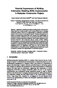
Furthermore, virtual mock-ups such as
laboratories or building envelope can be provided to the designer and the owner. This would help to visualize, better understand, and make decisions on the aesthetics and the functionality of the space. As depicted in figure 5 and presented in the BIMForum Conference in San Diego, virtual mock ups can be used to review 3D shop drawing of the building envelope (Khemlani, 2011). The virtual mock ups help to communicate and collaborate among the project participants. It promotes planning, and sequencing the curtain wall construction. Even though a virtual mock up is cost efficient in comparison to a physical mock-up, a physical mock-up may still be required if a member such as 13
casework drawer or an assembly of the building such as a curtain wall need to go through a series of physical tests. Hence, virtual mock-ups could become a good standard to initiate the mock up process and an actual mock-up may be necessary after the virtual mock up is approved.
Figure 5: Exterior Envelope Virtual Mock up for 3D Shop Drawing Review (Khemlani, 2011)
2.3.2 3D Coordination Collaboration of the construction team with the architect, engineer and the owner is preferred to be started on early stages of design phase. At that time, the Building Information Modeling shall immediately be implemented.
If the architect is only
providing 2D drawings, then the construction manager should convert the 2D drawings to 3D intelligent models. When the specialty contractors, especially the MEP contractors and the steel fabricators are involved, they need to spatially coordinate their work. The 3D coordination can be started right after the model is created to ensure that any same space interference (hard clash) or clearance clash (soft clash) conflicts are resolved. Overall, the coordination efforts of construction manager and specialty contractors in advance of construction help to reduce design errors tremendously and to better understand ahead of time the work to be done. For example, Research 2 Tower Project for Colorado Denver Health Science Center distinguished itself with the implementation of BIM in comparison to Research 1 Tower project which had major complex mechanical system problems. The BIM usage for Research Tower 2 included 3D MEP coordination 14
as shown in figure 6, work planning for concrete placement, and assembly instruction models. The benefits for Research 2 project included 37% reduction in coordination RFIs, and 32% reduction in coordination change orders (Young, 2009).
Figure 6: Layers of Complex Systems at Research 2 Tower Vivarium (Young, 2009)
2.3.3 Prefabrication Prefabrication reduces field labor cost and time and increases accuracy in a good quality construction. There are more tools and options readily available in a controlled environment of the jobsite to perform work more precisely, and less costly in a shorter period of time. Prefabrication requires design and field accuracy. Building information models can provide this level accuracy by including the specifications, sequence, finishes, and the 3D visual for each component. However, the construction team must make sure that the BIM is interoperable with the software used by fabricators. This way the contractors can use the BIM and generate details for the product in their fabrication software. Once the details are approved, the products can be fabricated using Computer Numerical Control (CNC) machines.
Furthermore, the construction managers must
administer the procurement schedule of the products. Overall, the prefabricated products must be delivered to the jobsite on time. Difficult steel connections generated in Building Information Model can be welded offsite. The welding of these small complex elements in advance of steel erection can save time and money. Furthermore, BIM helps to timely modify designs to eliminate 15
or reduce use of beam penetrations that may result from MEP conflicts. A few beam penetrations may become inevitable for complex project. A good coordination of these penetrations with BIM technology advocates determining the beam penetration locations and prefabricate offsite. Prefabricated beam penetrations would save tremendous time, money and effort in comparison to onsite beam penetrations. Moreover, roof penetrations for concrete rooftops should be sleeved prior to concrete pour at the roof level. Supplemental steel for each penetration may be required. These penetrations can be coordinated with BIM when the specialty contractors are on board (LeBlanc, 2010). Curtain wall systems whether panelized or stick system, can be used with BIM to prefabricate parts and components. Panelized curtain wall systems may be considered for the schedule purposes. Stick systems require the use of assembly of each one of components onsite where as the panelized systems already come prefabricated with all the components which includes, insulation, glazing, stone, framing, etc. Walls, rooms, and houses can be virtually designed and constructed with Building Information Model. These walls, rooms and houses can be prefabricated with roughed mechanical, electrical, plumbing (MEP) components. Final MEP connections can be made once the prefabricated components are assembled onsite. In healthcare and biotechnology projects, various equipment such as Biosafety Cabinets (BSCs), fume hoods, autoclaves, cage washes, and MRIs, etc. may be required. These equipments may require some type of coordination with MEP contractors. For instance, fume hoods may come with prefabricated piping for vacuum, gas, or nitrogen lines at laboratories. BIM can be used to determine the exact location of the fume hood and more importantly, the drop in location to the prefabricated piping at the fume hood. This enables the in-wall roughing and plumbing drops of the piping work before the fume hoods come to the site. Moreover, the electrician can pull cables to junction box to later tie into the circuits for lights, outlets, and fan. Lastly, the ductwork contractor can use the 16
information from the BIM to drop its branch duct so the fume hood can later be tied in. Overall, Building Information Modeling can help achieve the implementation of the MEP roughing work by promoting collaboration of information exchange between the subcontractors. BIM can help to coordinate between casework installers and MEP contractors. For example, island benches (cores) are prefabricated with electric outlets, and gas turrets. BIM can be used to determine the roughing locations. Then, the electrical circuits of the island benches can be roughed to a junction box. The plumbing pipes can be fed to the horizontal branches above the ceiling. Overall, the roughing can be completed successfully with the use of Building Information Modeling process. Pipe manufacturer could use BIM to gather coordinated piping locations, lengths and sizes for its fabrication software as long as the interoperability is possible. This allows in-wall drops including hot, cold, drain/vent, vacuum, etc. to be prefabricated. The drops typically stick out a foot from the wall to provide connection to the horizontal branches above the ceiling. Furthermore, if pipes need to be weld, they must come at manageable sections. Pipes typically come to jobsite 5 to 10 feet sections. Welding small sections of black iron pipe with four inches or bigger diameter would be feasible to weld offsite whereas two 10 foot sections welded offsite would not be manageable. Also, offsets and joints would prefer to be prefabricated. Overall, it is ideal to prefabricate all the small pieces in a controlled environment with readily available equipment which would yield more efficient, higher quality, and less costly products (LeBlanc, 2010). BIM can be used to enhance the information exchange of the products between participations. Furthermore, it is used to virtually coordinate the location and routing of the products. Based on this information, the products can be detailed using the fabrication softwares. Once the material is prefabricated and arrives on site, the foreman of the
17
specialty trade coordinates with the general superintendent to ensure that he is making the virtual design and construction a reality.
2.3.4 Construction Planning and Monitoring The construction planning involves the scheduling and sequencing of the model to coordinate virtual construction in time and space.
The schedule of the anticipated
construction progress can be integrated to a virtual construction. The utilization of scheduling introduces time as the 4th dimension (4D). There are two common scheduling methods that can be used to create 4D Building Information Model. These are critical path method (CPM) and line of balance. In the Critical Path Method, each activity is listed, linked to another activity, and assigned durations. Interdependency of an activity is added as either predecessors or successors to another activity. Moreover, the duration of the activities are entered. Based on the dependency and duration of the activities, the longest path is defined as the most critical path.
The activities defined in the longest path are defined as the critical
activities. These activities do not have any float. In other words, if these activities are not completed within anticipated duration, the total duration of the project will be further pushed out. Overall CPM is a commonly used technique that helps projects stay within schedule. Line of Balance technique uses location as the basis for scheduling. This method is an alternate to the CPM. It is advantageous for repetitive tasks to increase labor productivity. In this method, activity durations are based on the available crew size and the sequence of the location. Productivity of the labor force can be altered as needed to accurately depict the construction schedule. The approach focuses on the locations being completed by a trade before the other trade moves in. This reduces the number of
18
mobilizations and resources. Overall, line of balance is a good scheduling method to plan and monitor repetitive tasks during construction progress. (Kenley, 2010) The planning through using BIM enhances site utilization, space coordination, and product information. A 4D model can either include a site logistics plan or tools such as SMARTBOARD on top of a virtual construction can be utilized to visually depict the space utilization of the job site. The model must include temporary components such as cranes, trucks, fencing etc. Traffic access routes for trucks, cranes, lifts, excavators, etc. need to be incorporated into the BIM as part of the logistics plan. For example, the site logistics planning for the Hennessy Centre steel erection is depicted in figure 7 (Collins 2011). Moreover, the site utilization consists of lay down areas, site work progress, and location of trailers and equipment and hoist assembly. Similarly, when the building is being closed in, the space coordination must be managed for the roughing and eventually finishing activities.
Figure 7: Hennesy Centre Safety and Site Logistics Planning (Collins, 2011)
4D BIM can be used as a visualization tool to identify the safety features that will be required at different times. Based on these observations, the Temporary safety related structures such as rails and fences can be modeled in the BIM and the safety related activities can be integrated into the schedule. Once the model is used as a planning tool 19
for safety, the 4D model can be used to monitor the safety precautions taken at the jobsite. Overall, 4D BIM can be used a proactive approach to enhance the planning and monitoring of the jobsite safety. Construction managers must plan for coordination, shop drawings approval, fabrication, transportation, and installation times. They need to make sure the lead times for the material is accounted for so that it can have enough time to be installed or assembled. They can update this information on their 4D models. There are several field data acquisition systems that can be used with 4D BIM to keep track of the progress of .the construction. Radio Frequency Identification and 3D laser scanning Radio Frequency Identification (RFID) can be used to keep track of the material delivery status. The use of RFID is ideal for the prefabricated components of a project such as precast concrete panels. RFIDs can be linked into the BIM to show that the elements are in the correct location. For instance, a tagged projector can be linked to the element’s type property in the BIM. The BIM and RFID integration helps to keep track of the location of the projector and indicate that the material is in the designed location once it is installed (Meadati, 2010). RFIDs can alternatively be used to plan and monitor the workforce. They can be tagged to the hard hats of the trades to identify the manpower and the location of the workers for the day (Yazici, 2010). The daily activities of workman can be monitored closely to ensure that the manpower is adequate and that the labor activity is suffice to the planned 4D schedule. 3D Laser Scanning can be used to monitor the progress of designed Building Information Model. 3D laser scans and register point clouds of geospatial information which then can be processed to the designed Building Information Model. At that stage, the scanned as-built data can be manually checked against the original designed model to detect any deviations.
However, there are no current algorithms to make this an 20
automatic process (Hajian, 2009). Overall, the 3D laser scanning technology can be a good quality control tool for new projects. For renovation projects with no 3D models, the laser scanning can be a good process to identify the current location and status of building components. The visualization can be helpful for space coordination in the renovation projects. Construction managers can use BIM and the robotics total station technologies for accurate building practices. Site survey points generated in the Building Information Model can be uploaded to the robotic total station. Based on the points generated from the model, the field staff then can lay out all of the points. For instance, the accurate positioning of the hangers would ease the coordination of the MEP contractors ("Using BIM and IPD to Design & Build the Hospital of the Future." 2010). Furthermore, field staff can survey the components of the building with robotic total station to ensure that they are built per designed model within acceptable tolerance range. This proactive quality control approach would prevent any subsequent conflicts. Overall, robotic total station uses the information from BIM to survey both for construction and quality control purposes. Planning and monitoring is an extremely important part of the construction. The construction manager can use various 4D BIM enabled tools to enhance the quality control process. Overall, construction planning and monitoring with 4D BIM is a great process to build a facility per the designed model.
2.3.5 Cost Estimation The two main elements of a cost estimate are quantity take-off and pricing. Quantities from a Building Information Model can be extracted to a cost database or an excel file. However, pricing cannot be attained from the model. Cost estimating requires the expertise of the cost estimator to analyze the components of a material and how they 21
get installed. If the pricing for a certain activity is not available in the database, cost estimator may need a further breakdown of the element for more accurate pricing. For instance, if a concrete pour activity is taking place, the model may account for the level of detail for the rebar, wire mesh, pour stop, formwork, concrete etc., but not include it as part of the quantity take-off extraction. Cost estimator may need this level of detail from the model to figure out the unit price which consists of the unit material cost, unit labor cost, overhead and profit. The unit labor cost is driven by the mobilization and installation durations, and the labor wage while the unit material cost is the sum of the material costs used for the activity per unit. Once the unit price is attained, the cost of the entire activity can be attained by multiplication of the total quantity extracted from BIM and unit price. In Building Information Model, the data output is as good as the data input. It is significantly important to have the constructor and the designer to agree on component definitions.
For instance, if an architect is using concrete slab to show the roof for
modeling purposes, the roof quantity information will not be accurately accounted for quantity extraction purposes in the model. Overall, the BIM technology is a great tool to optimize the productivity of the estimators through quantity extraction from the model especially if the construction and design team work collaboratively.
2.3.6 Record Model Construction Managers can provide a record Building Information Model to the owner at the end of a project. The model includes the integration of the as-builts from the subcontractors. Furthermore, each object property in the model can also include links to submittals, operations and maintenance, and warranty information. Centralized database can help the facilities department to find information easier. Record model can be used to manage security and safety information such as emergency lighting, emergency power, 22
egress, fire extinguishers, fire alarm, smoke detector and sprinkler systems (Liu, 2010). Furthermore, the facility team can analyze energy efficiency of a virtually built model. In addition to that, facilities team can plan with record model to maintain and renovate buildings by tracking spatial information such as furniture, equipment, and MEP (mechanical, electrical, and plumbing) connections. Finally, the facilities department can use the model to generate cost and schedule impacts for maintenance and renovation projects. Overall, a record model can be utilized to optimize facility management and maintenance. Generation of Building Information Model as a record model is an area in the process of development.
The interoperability of the record model with various
applications could potentially be a challenge. Furthermore, the owner needs to be willing to allocate funding to train employees, update and maintain the record Building Information Model (Keegan, 2010). As the benefits of the record model are realized, the owners will be more demanding of the record Building Information Model. An accurate record model that contains the scope of the project and the needs of the facilities department can help the owner manage and maintain the building tremendously. This can leave a long lasting positive impression of the construction manager to the owner of the project.
2.4 BIM Tools There are plenty of Building Information Modeling tools. This subsection will identify these products. The following table, figure 8, depicts the BIM authoring tools and their primary functions. The list includes MEP, structural, architectural, and site work 3D modeling softwares. Some of these softwares are also capable of scheduling and cost estimation.
23
Product Name
Manufacturer AEC Design Group
Cadpipe HVAC Revit Architecture
Autodesk
AutoCAD Architecture
Autodesk
Revit Structure
Autodesk
Revit MEP AutoCAD MEP AutoCAD Civil 3D
Autodesk Autodesk Autodesk AEC Design Group
Cadpipe Commercial Pipe DProfiler Bentley BIM Suite (MicroStation, Bentley Architecture, Structural, Mechanical, Electrical, Generative Design) Fastrak SDS/2 Fabrication for AutoCAD MEP
3D HVAC Modeling 3D Architectural Modeling and parametric design. 3D Architectural Modeling and parametric design. 3D Structural Modeling and parametric design. 3D Detailed MEP Modeling 3D MEP Modeling Site Development 3D Pipe Modeling
Beck Technology
3D conceptual modeling with realtime cost estimating.
Bentley Systems
3D Architectural, Structural, Mechanical, Electrical, and Generative Components Modeling
CSC (UK) Design Data East Coast CAD/CAM
Digital Project
Gehry Technologies
Digital Project MEP Systems Routing ArchiCAD MEP Modeler
Gehry Technologies Graphisoft Graphisoft
HydraCAD
Hydratec
AutoSPRINK VR
M.E.P. CAD
FireCad
Mc4 Software
CAD-Duct Vectorworks Designer Duct Designer 3D, Pipe Designer 3D
Tekla Structures
Micro Application Nemetschek QuickPen International RISA Technologies Tekla
Affinity
Trelligence
Vico Ofice
Vico Software
PowerCivil Site Design, Site Planning
Bentley Systems Eagle Point
RISA
Primary Function
3D Structural Modeling 3D Detailed Structural Modeling 3D Detailed MEP Modeling CATIA based BIM System for Architectural, Design, Engineering, and Construction Modeling MEP Design 3D Architectural Modeling 3D MEP Modeling 3D Fire Sprinkler Design and Modeling 3D Fire Sprinkler Design and Modeling Fire Piping Network Design and Modeling 3D Detailed MEP Modeling 3D Architectural Modeling 3D Detailed MEP Modeling Full suite of 2D and 3D Structural Design Applications 3D Detailed Structural Modeling 3D Model Application for early concept design 5D Modeling which can be used to generate cost and schedule data Site Development Site Development
Figure 8: BIM Authoring Tools (Reinhardt, 2009)
24
A variety of shop BIM tools for drawing and fabrication are available or structural and MEP contractors as depicted in figure 9: Product Name Manufacturer Primary Function Cadpipe Commercial Pipe AEC Design Group 3D Pipe Modeling Revit MEP Autodesk 3D Detailed MEP Modeling SDS/2 Design Data 3D Detailed Structural Modeling Fabrication for AutoCAD MEP East Coast CAD/CAM 3D Detailed MEP Modeling CAD-Duct Micro Application Packages 3D Detailed MEP Modeling Duct Designer 3D, Pipe Designer 3D QuickPen International 3D Detailed MEP Modeling Tekla Structures Tekla 3D Detailed Structural Modeling Figure 9: BIM Tools for Shop drawing and Fabrication (Reinhardt, 2009)
Revit Architecture provided by Autodesk Inc. has built-in sequencing options. Each object can be assigned a phase. Revit then uses snapshots of the model for each phase creating a simple sequencing for the viewers. Currently, there are a lot of architects that are using Revit Architecture. Various BIM construction management and scheduling tools are available as depicted in figure 10. BIM Construction management tools that support coordination are Navisworks Manage, ProjectWise, Digital Project Designer, and Vico. Furthermore, Vico, Navisworks Timeliner, Innovaya and Synchro support BIM and schedule integration. Navisworks, Synchro and Vico Ofice softwares will be discussed in further detail. Product Name Navisworks Manage Navisworks Scheduling
Manufacturer
BIM Use Clash Detection Autodesk Scheduling Clash Detection ProjectWise Bentley Scheduling Digital Project Designer Gehry Technologies Model Coordination Visual Simulation Innovaya Scheduling Solibri Model Checker Solibri Spatial Coordination Synchro Synchro Ltd. Planning & Scheduling Structure-centric Model Tekla Structures Tekla Schedule driven link Coordinate Vico Office Vico Software Scheduling Estimating Figure 10: BIM Construction Management and Scheduling Tools (Reinhardt, 2009)
Autodesk Navisworks Manage is well known for its clash detection feature. However, it comes with a feature called Timeliner to simulate construction schedules. 25
Timeliner can link Microsoft Project, and Primavera project planner with various BIM (ie. Revit), CAD and Laser Scan formats. Unfortunately, Timeliner is only a unilateral information exchange platform. Similar to Autodesk Navisworks Manage, Tekla BIMsight runs clash detections. The user can combine models and add comments. This brand new product developed by Tekla is likely to be quickly adopted throughout the world since it is a free product to use and share ("What Is Tekla BIMsight?", 2011). There are several very powerful middleware softwares. The two most common are Innovaya and Synchro. Both are capable of providing integration services between the common scheduling softwares (Primavera or Ms Project) with various types of BIM softwares. Vico Software Inc. provides BIM software packages geared more towards the construction management industry.
Its construction software package includes
Constructor, Estimator, Control and 5D presenter. Building Information Model is developed in Constructor. Quantities and costs are estimated in Estimator. The data is imported from Constructor 3D model to Estimator. Vico’s Estimator software features include processing of quantities, tracking of model revisions, addition of margins, and creation of bid packages. Location based scheduling is used via Vico’s Control software.
This is an
approach that optimizes the productivity of works by using line of balance method. Simulations are available through the Presenter.
Vico’s Control software can also
integrate with other scheduling softwares. Control has a bidirectional link to Primavera or Microsoft Project. Project schedule in Controller can be exported to Primavera or Microsoft Project and vice versa.
26
2.5 How much does BIM cost? Building information model costs and savings depends on many factors. Costs are based upon the level of detail of the model, complexity of the project and the expertise of modeling team in the technology.
The level of detail (LOD) can be
categorized thru system published by AIA. LOD 100 is conceptual stage. LOD 200 is approximate geometry stage. LOD 300 is precise geometry stage.
LOD 400 is
fabrication stage. LOD 500 is as-built stage. (Bedrick 2008) The main uses of BIM for construction managers include visualization, 3D coordination, prefabrication, construction planning and monitoring, quantity take offs, and record model. Project savings are considerably high if the Building Information Modeling is used during the early design phase. This is mainly due to coordination efforts that yield to minimization of trade conflicts in the field. The owner, architect, and engineer can eliminate some of the coordination issues in LOD3 via BIM. Later, the subcontractor can provide more detailed shop and fabrication drawing as LOD 4. At this stage, construction manager can coordinate the approval process of the shop drawings. Furthermore, construction manager can provide more detailed and accurate schedule and cost estimation as the LOD increases from 100 to 400.
Lastly, record Building
Information Model can be achieved in L500. Overall, the different uses of BIM for construction managers as indicated in figure 11 can be realized at various stages of LOD that would yield to cost savings.
27
Figure 11: Level of Detail Definitions (Bedrick 2008)
Complexity of the project is related to the type of construction such as residential, institutional, healthcare and research, commercial, governmental. Building information models for residential construction can be simpler models.
For healthcare,
pharmaceutical, research and biotech projects, BIM would require better coordination for space due to the increased MEP and equipment required for the work. For institutional construction, colleges such as WPI promote BIM. For government projects, GSA and
28
army corps are requiring the BIM to be used. Overall, type of construction could be a determinant factor as to how much BIM will be used. Becerik-Gerber and Rice (2010) conducted a survey on BIM use to the construction industry.
Of the 424 responses, 9.4% construction managers, 9.9%
contractors, and 2.4% subcontractors of the 424 respondents participated. The rest of the participation breakdown is provided in figure 12. Even though the study did not particularly focus on construction managers at risk, it provided a good insight on the BIM use, costs and savings.
Figure 12: Respondent Occupations (Becerik-Gerber, 2010)
The top uses of BIM for contractors were clash detection, visualization, and creation of as-built models. Based on the survey results, the industry wide uses of Building information model is listed in figure 13:
29
Figure 13: BIM uses for the survey participants (Becerik-Gerber, 2010)
The general trend in the construction industry is to handle the BIM process inhouse. However, construction managers and contractors are more likely to outsource than the designers. The design and construction firms often pay for the software, upgrades, hardware, hardware maintenance and training costs. In other words, the firms are unable to pass on the costs of performing BIM services thru fees. They would make up for these costs in terms of their overhead cost. They also reduce the number of men-hours needed for drawing production The survey depicted in figure 14 below indicates that overall costs associated for the BIM technology is usually less than 2% of the overall net revenue:
30
Figure 14: Ratio of software, software upgrades, hardware, hardware maintenance, and training costs to overall net revenue (Becerik-Gerber, 2010)
As the use of BIM has its own costs, it comes with rewards. Depicted in the figure 15, 41% of respondents stated that the BIM use increased the profitability of the project. Other BIM users may not feel change in project profitability and think that the BIM’s advantages do not pass beyond marking, design, and visualization efforts. The first time users of the BIM may feel a negative impact on their profitability due to a new investment in technology and learning curve that comes with it. The consistent participants of the Building Information Modeling are likely to reap the benefits of BIM and notice increase in their profits. Lastly, the majority of the participants also indicated that the use of BIM reduced cost and schedule of the project. Overall, the cost of the BIM and its supporting technologies can be expensive to begin with. However, the powerful uses of BIM increases profits, lowers costs, and scheduling time.
31
Figure 15: Effect of BIM use on project profitability (Becerik-Gerber, 2010)
32
3 Methodology The goal of this project was to examine the uses and benefits of BIM for construction managers and analyze BIM based scheduling. First, the literature review included the definition and the use of BIM and its tools. There were a couple of case studies presented in this project. The first case study, MIT Koch project, included real life examples of BIM uses and benefits. The second case study, a prototype house project, examined the 3D and 4D Building Information Modeling as well as BIM based scheduling. Overall, the literature review and case studies provided an insight on the benefits of using BIM and its applications.
3.1 Literature Review In Chapter 2, the terms BIM, “lonely” BIM, “social” BIM, “Hollywood” BIM, and related terminologies were defined. The use of BIM which include visualization, coordination, prefabrication, construction planning and monitoring, cost estimation, and record model were further examined.
4D BIM tools were reviewed. Finally, cost
implications of Building Information Modeling were studied.
3.2 Case Study: MIT Koch Institute MIT Koch Center project was used as a case study to understand the use and benefits of BIM in detail. The study includes the utilization of BIM for visualization, 3D coordination, prefabrication, construction planning and record model in a cancer research facility.
33
3.3 Case Study: Use of BIM Tools The primary focus of this project was the use of Building information models and 4D integrators. 5th dimension “cost estimation” were not be studied due to the time limitation of the project.
3.3.1 3D Modeling of a House Student licensed version of Revit Architecture 2010 was downloaded from Autodesk’s student community website to develop a 3D house model. First, a new Revit file was created and saved. Then, the perimeter walls were created. Once the perimeter walls were completed, the interior walls are created.
Then, the foundation walls,
flooring, doors windows, roof, stairs, deck were created. Furthermore, the rooms were tagged. No mechanical, electrical, plumbing elements were created for this study. The differences of 3D modeling and 2D drafting were reviewed. Furthermore, the granularity of objects including the decomposition of the elements was explored.
3.3.2 4D Modeling of a House 4D modeling required the development of a 3D model as well as the schedule. The 3D model was created in Revit Architecture 2010. The Microsoft Project used the critical path method to create the schedule. Synchro’s 4D BIM tool was downloaded through its website. In this project, it was utilized as the integrator of the Revit model in IFC format and the Microsoft Project in xml format. Once the model and the schedule were imported in to the Synchro’s integration tool, the IFC resources which was a list of building elements created in BIM was linked to the activities. Once the 4D linking was completed, play focused time and animation could be utilized to create videos of the 4D model. Finally, the video file could be exported as an avi movie format.
34
3.3.3 BIM as the Main Generator for 4D Scheduling For large sized projects, there were usually about 100 activities at proposal and schematic design stages. During design development, the schedule activities could be between 500 and 1000. At construction document stage and further, the activities could range from 1000 to 10000 or more. As the project progresses into the construction document, it would be ideal to capture all of the elements to ensure that there is no missed information. Submittal review, procurement, delivery and installation activities could be tracked together for building components. Integration tools that may extract out information from the BIM to a schedule were researched. According to BIM and Project Planning article dated February 2007, Autodesk Consulting developed a bidirectional link between Revit and MS Project. This add-on exported building components by level and category for scheduling and resource tasking. In turn, the Revit components could be updated with start and finish dates. The building components could then be filtered by date. Revit phases could also be updated via the MS Project. Autodesk’s consulting developer network and customer service were contacted to acquire about this add-on product and they could not confirm the availability of this bidirectional link between Revit and MS Project add-on. After careful review of the Autodesk website, there was no evidence of availability of this bidirectional link between Revit and MS Project add-on. Similarly, Bim Jet developed Schedule Connect via Application Programming Interface (API) to use the REVIT model as the basis for scheduling. However, Bim Jet suspended the development of this tool due to lack of industry response (Schroeder, 2010). Industry Foundation Classes (IFC) generators were researched to create a BIM based schedule. IFC File Analyzer and Open IFC Java Toolbox were tried. IFC File 35
Analyzer converted the IFC file created from Revit Architecture to Microsoft Excel. The generated output provided entity breakdowns, such as columns, doors, walls, windows etc. Similarly, IFC Java Toolbox was used to generate IFC entities by floor in Java. Synchro integration software was further studied to apprehend its usage on BIM based scheduling.
When the IFC file was being imported, the “create tasks and
assignments for imported sources” box was checked off to create schedules automatically based on the IFC entities for each floor.
This quick linking approach enabled the
generation of a 4D model within seconds. The generated IFC entities on the schedule could be also exported as a schedule file to use for scheduling purposes in MS Project or Primavera. Time consuming but a more elaborate BIM based scheduling approach was further studied and applied in Synchro. First, summary tasks were created in scheduling software and were imported to Synchro. The selected IFC resources generated from the imported model was simultaneously created and linked as subtasks to the summary tasks in the schedule. Lastly, the 4D schedule based model were attempted to be synchronized with the imported schedule and the Building Information Model.
3.4 Interviews, Lectures, and Presentations A series of interviews with the leading construction managers in Massachusetts was conducted to better understand the current use of the Building Information Modeling. Furthermore, Building Information Modeling lectures of 2010 spring semester at WPI with the courtesy of Professor Salazar were attended. Each lecture had a guest speaker that presented the use of BIM from his or her own perspective. Also, the presentation of the Boston Revit Users Group at WPI was attended. It included the various discussions including definition of BIM, benefits of BIM and the setbacks on BIM technology which included interoperability. 36
4 Results This section provides results derived from the two case studies. First, results of construction manager’s application of BIM process for a research facility are discussed. Secondly, this section presents findings on the use of several BIM tools on a small prototype house project.
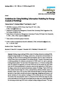
4.1 Case Study: MIT KOCH MIT Koch Institute is a 360,000ft2 nine story cancer research building located in Cambridge, MA. Designer of the project is Ellenzweig. The construction manager is William A. Berry & Sons Inc. The building consists of 45,000ft2 vivarium, and 275,000ft2 wet labs, 10,000ft2 lobbies and common spaces, and 30,000ft2 mechanical space, and underground tunnels to Stata Center and Building 68. The following VICO rendering, figure 16, shows an exterior view of the MIT Koch project:
Figure 16: MIT Koch Exterior Rendering
Koch Institute was a fast track project. Duration of this project spanned from March 2007 to November 2010. Beneficial occupancy for vivarium was September 1, 37
2010.
The substantial completion of the project was November 1, 2010.
The
construction team assisted the design team during the preconstruction phase with exterior façade and mechanical trades. The mechanical team work included use of BIM which will further be discussed. Pre-purchased scope of work included limestone, curtain wall, structural steel, misc metals, Air Handling Units (AHUs), exhaust fans, switchgear, generator, and vivarium equipment. 3D Vico steel framing rendering is depicted in figure 17:
Figure 17: MIT Koch Steel Framing Rendering
The construction management company, Berry, used various technologies used at the Koch project. Timberline Project Management was utilized for project management tasks. VELA System’s field management applications, Vela Safety, Slip Management, and Punchlisht were used to create databases to track safety and material and times slips, and execute punchlist items. FTP server and Ontrac site, an online collaborative platform design by Berry, were utilized for document tracking. Lastly but not the least, Berry provided BIM services thru Vico Systems. 3D Vico steel framing rendering is depicted in figure 18: 38
Figure 18: Vico Model MEP and Structural Rendering
Animal holding room and procedure room for the vivarium were mocked up virtually via BIM. Equipment, fixture, switch locations were confirmed via the mock up. The virtual mock-up set a clear understanding of how the space was going to be used prior to construction so there were no misrepresentation to what the owner needed. Figures 19 and 20 depict renderings of the both virtual mock up rooms:
Figure 19: Animal Holding Room 703B Rendering - Stainless Steel Casework, Animal Transfer Station, Cages Animal Watering system, epoxy flooring, etc.
39
Figure 20: 703C Procedure Room Rendering - stainless steel casework
At the design development phase, the architect generated two-dimensional CAD drawings. The construction manager, Berry, developed base Building Information Model from 2D drawings. Every three to four weeks, modeling of two floors were completed. It took 16 weeks to model design development drawings in 3D. The BIM software, VICO Constructor, was utilized to produce the 3D model.
The developed model
identified conflicts and drawing inconsistency issues as a package known as constructability report. Constructability report included 500 to 600 items per floor for conflicts, and gaps and errors on the drawings. As depicted in Figure 21, the report described the issue and modeling assumptions. It referenced floors, grids, and 2D designer drawings, and categorized the severity of the issue.
Berry emailed the
constructability report to the design team for review. Within a week of constructability report issuance, project team which consisted of the construction manager, architect and design consultants gathered and made decisions on modeling assumptions. The main focus of the meetings was the review of critical items that would impact the project. The designer utilized and integrated the outcome of constructability review to the project drawings.
40
Figure 21: Constructability Analysis Sample Page (1 of 2)
Once the construction drawings were issued, Berry updated the design development model two floors at a time. Each update took 3 weeks. The constructability analysis report was run as depicted in figure 22 and made available to the project team. There was an average of 100 items per floor. Since the majority of the critical items were eliminated during the design development stage, the constructability report review was tremendously reduced. The meetings did not become a necessity as it was in the design development stage.
41
Figure 22: Constructability Analysis Sample Page (2 of 2)
MEP Subcontractors used 80% of the centerlines from Berry’s construction document coordinated Vico model as shown in the figure below. HVAC contractor J.C. Higgins, plumbing contractor American Plumbing and Heating, electrical contractor Gaston Electrical, and fire protection contractor E.M. Duggan sequentially modeled their highly detailed coordination drawings. For each floor, J.C. Higgins’ subcontractor, McCusker Gill first modeled detailed ductwork coordination drawings in CAD-Duct software package provided by Micro Application Packages ltd. Secondly, J.C Higgins used AutoCAD MEP by AutoDesk to produce detailed model for piping. Thirdly, the plumber utilized AutoCAD MEP to develop detailed coordination model. Then, the electrician used AutoCAD MEP to build the electrical detailed coordination model. Lastly, sprinkler contractor utilized AutoSPRINK VR by M.E.P. CAD to produce fire
42
protection coordination drawings.
The sequential process of coordination drawings
completion per floor took about a month. More than one floor was worked on at a time. Berry’s MEP manager held weekly meetings with the MEP trades, architect and the engineers. He utilized Navisworks by AutoDesk, a clash detection software, to identify conflicts. Basement was observed to be the floor with the most conflicts. Few clashes were found and were quickly resolved at weekly coordination meetings by the MEP manager and subcontractors.
During MEP coordination, there were about 30
clashes in the basement, 10 to 20 clashes in 1st through 6th floors, 30 in the vivarium and 10 in the penthouse. The most amount of coordination was required in the basement because the floor consisted of main electrical, mechanical and fire pump rooms as well zebra fish lab. Coordination of space for electrical service, water services, fire pump, rain water drain and sewer lines were required. Overall, MEP coordination lasted six months. The use of building information model was compared to a similar size and scope of a project to identify quantifiable benefits of BIM. MEP Coordination schedule was reduced from eleven months to six months.
VICO model reduced 61% of MEP
coordination time usually needed for coordination. Benefits also included 62% RFI reduction (Malenchini, 2010). Bulletins issued directly related to coordination were only two. Furthermore, 83% of beam penetrations were used and remaining penetrations hold money was returned to the owner. The production and installation became cost effective and saves time when multiple fittings were prefabricated into one piece. At MIT Koch facility, mechanical contractor prefabricated chilled water and steam manifolds as well as hot water piping for hot water pumps and heat exchangers. These prefabricated materials were installed at a very crowded area in the penthouse while multiple trades were performing other work. If the manifolds were not prefabricated, it would have required more space onsite, and each 43
manifold would have taken 6 days of installation instead of 3 days. Space was available at the manufacturing facility. Temperature, humidity and weather conditions were controlled. Overhead cranes and specialty tools such as leveling device and turn tables were used to assist with welding. The controlled environment, availability of equipment and space results in faster and higher quality materials while saving time and labor in the field. Figure 23 is a rendering of the chilled water and steam manifolds at the penthouse near the air handling units:
Figure 23: Prefabricated CHW and Steam Manifolds
As mentioned in the background section, in-wall drops including hot, cold, drain/vent, RO (2 pipes), vacuum, etc. can be prefabricated using BIM. The drops typically stuck out a foot from the wall to provide connection to the horizontal branches above the ceiling. There were about three hundred typical drops behind sinks at the MIT Koch facility. If the drops were not prefabricated, it would have taken 3 hours extra to assemble and install per each drop. Overall, prefabrication saves time, labor costs, and made the job smoother. Figure 24 depicts an installed prefabricated assembly of the inwall drops:
44
Figure 24: Prefabricated Laboratory Tempered Water, Hot water, Cold Water, Lab waste Lines
Similar to the drops, plumbers also used BIM to prefabricate the horizontal runs at the bathrooms as depicted in figure 25. This also saved time and labor costs.
Figure 25: Prefabricated horizontal runs at the bathroom
Fume hoods came pre-piped to the top of the fume hood. Once the unit was set, and the coordinated BIM model smoothly enabled the dropped duct to be connected. Similarly, the plumber utilizing the coordinated Building Information Model ran the branches prior to fume hood arrival and made connections at the top after the equipment arrived as shown in figure 26.
45
Figure 26: Pre-piped gas line with Fume hood assembly
Ten Air Handling Units (AHUs) were installed at the penthouse. AHUs were double stacked. AHUs were prefabricated and came in few pieces. Long before AHU installation, construction manager performed spatial coordination of Air Handling Unit (AHU) rigging at penthouse via BIM tools. Vico Control was utilized to sequence the AHU rigging. The 4D modeling of AHU rigging coordination was visualized via Vico 5D Presenter. The sequencing included careful planning of the AHU rigging turns and spatial coordination with storm and drain lines before rigging and clearance on the ceiling. The construction planning helped the team to prepare for a large rigging in advance of actual construction. This helped to avoid delays and additional costs during the actual AHU rigging process. Construction manager provided record Building Information Model to the owner at the end of the project. All pipe tagging were included. Ductworks were labeled with the AHU unit designation. All the information pertaining to maintenance and parts were included as part of record model. Overall, the valuable information built into the record model could potentially help the owner with maintenance and renovation. As the record model is the last step to the uses of BIM, the record model in my opinion will be a positive long lasting impression and information database to the owner. 46
At MIT Koch project, the construction manager and its subcontractors has implemented five out of the six BIM uses identified in the literature review: visualization, 3D coordination, prefabrication, construction planning, and record model. The only BIM use that was not introduced to the project was the cost estimation known as 5D BIM. Visualization such renderings and animal room mock ups were introduced. It helped the project team collaboratively visualize expectancy and needs of the project before construction. 3D coordination was implemented via Vico model and later with MEP coordination. This process reduced MEP coordination time and RFIs and avoided costs. Prefabrication such as chilled water manifolds and in-wall drops yielded faster and higher quality materials while saving time and labor in the field. Construction planning was implemented only at AHU rigging.
This avoided schedule delays and cost during
construction. Finally, a detailed Vico record model was submitted to the owner. This could potentially help the owner with maintenance and renovation of the facility while it may leave a long lasting impression of the construction manager to the owner. Figure 27 summarizes the evident BIM uses and benefits for the MIT Koch project. BIM Use Visualization 3D coordination Prefabrication
Construction planning
MIT Examples -Renderings -Animal holding room mock up -Vico model -MEP coordination -Chilled water and steam manifolds -In-wall drops -AHU rigging plan
Cost estimation -N/A Record model -Vico model
BIM Benefits -Collaboratively visualize expectancy and needs of the project. -Reduced MEP coordination time -Reduced RFIs -Avoid additional costs. -Faster and higher quality materials. -Save time and labor in the field. -Avoid schedule delays during construction. -Avoid cost during construction. -N/A -Positive last impression to the owner. - Potential to Help owner with maintenance and renovation.
Figure 27: BIM Use and Benefits at MIT Koch Project
47
4.2 Case Study: Use of BIM Tools This section provides results on the use of Building Information Model tools. This includes formation of prototype building information model, interoperability of the model, integration of the model with schedule and BIM based scheduling.
4.2.1 3D Modeling of a House The creation of a 3D housing model using the Revit Architecture 2010 showed the powerful features of BIM. The creation of an element on a view such as floor plan translated correctly to a different view such as elevation view. This saved a lot of time in comparison to if the design were drawn in traditional 2D view. parametric modeling detected the conflicts of elements.
Furthermore, the
The use of this feature
eliminated duplication or overlapping of elements. Figure 28 depicts the prototype Revit house model created for this project:
Figure 28: Prototype Revit House Model
The Revit Architecture 2010 was not very flexible with generation of new elements. In other words, this BIM tool easily supported the alteration of currently available elements, but required time and investment to build new elements. For the 48
prototype model, the exterior insulated finish system (EIFS) on metal stud was changed to EIFS on wood stud in the element properties for the housing project to save time. Granularity of objects was another challenge for BIM tools. Revit Architecture 2010 supported the use of splitting, and grouping. For instance, the walls were split between each floor to enable the 4D BIM on a floor basis. However, decomposition of the elements was not available. For instance, if the EIFS on wood stud wall was modeled in the Revit model, the breakdown of the elements which included sheetrock, studs, insulation, vapor barrier, exterior skin, could not be separately selected in the model. Since this hindered the usability of detailed components for estimating, and scheduling purposes. The software industry has construction estimating tools available.
VICO
Estimator forms recipes which enabled the arrangement of all the activities and resources required to construct each component of a building. For instance, if a concrete column was required, formwork, reinforcing steel and concrete were the activities that would be noted in the Vico Estimator. Revit Model was exported as an Industry Foundation Class (IFC) to allow interoperability of the model with various BIM applications which included Vico Constructor, Navisworks Manage, and Synchro.
When the IFC format model was
imported to Vico Constructor, it was found that there was an interoperability problem. The railing and stair to the deck were missing. Furthermore, the rail to the stairs at the first floor balcony was missing. The prototype model imported to Vico Constructor with the missing stair and railings is depicted in figure 29:
49
Figure 29: Prototype House Model Imported to Vico Constructor
Similarly, the prototype model was imported to Navisworks Manage.
The
imported model showed a different interoperability problem. The deck railing was not located at incorrect orientation as depicted in figure 30:
Figure 30: Prototype House Model Imported to Navisworks Manage
50
The prototype model was imported to Synchro as depicted in figure 31. There were no interoperability issues. However, there were some modeling errors that were encountered and this is discussed in the next subsection.
Figure 31: Prototype House Model Imported to Synchro
The prototype house model illustrated benefits of parametric modeling in comparison to two dimensional computer aided drafting. The parametric model denied overlapping of the elements. Also, there were no errors, omissions or conflicts of information at different views. A few set backs were realized with the prototype house model. For instance, Revit Architecture 2010 required time and investment to build new elements.
Furthermore, the decomposition of elements was not available in Revit
Architecture 2010. Lastly, there were interoperability issues. When the prototype model was imported to Vico Constructor and Navisworks, there were some elements missing or incorrectly shown.
51
4.2.2 4D Modeling of a House The creation of 4D model involved the transition of the model via Industry Foundation Classes (IFC) from Revit Architecture to Synchro. During the transition, several challenges were found for the house project. Since some of the walls extended from 1st floor up to the roof, the IFC file was exported using Revit’s “split walls and columns by level” option for scheduling purposes as depicted in figure 32.
Figure 32: Revit IFC Export with “split walls and columns by level” Option
When the prototype model was imported to Synchro, the IFC import box showed that the walls were not imported successfully to Synchro. As depicted in figure 33, the exterior walls that needed to be split were not successfully imported.
52
Figure 33: The Prototype House Model Imported to Synchro after Revit IFC Export with “Split walls and columns by level” Option
Since the prototype house model was not successfully imported, the walls were split by floor manually in Revit Architecture 2010 and the issue was resolved permanently. This is a very important consideration that needs to be known by modelers depending on the emphasis given to the use of the model. Architects are not concerned about splitting the walls whereas builders do for construction planning purposes. Another challenge for the housing project was the displayed column error when the model was imported into Synchro as depicted in figure 34. To understand the problem, the wood columns were filtered in REVIT. It was obvious that extra wood columns were added accidentally that did not belong to the model. Hence, these columns were manually deleted. After these modeling errors were resolved, the IFC model was successfully imported to Synchro.
53
Figure 34: "ifccolumn error" in Synchro during IFC Prototype Model Import
Once the splitting and column issues were resolved The IFC prototype Model with necessary resources was successfully imported to Synchro as depicted in figure 35.
Figure 35: Prototype House Model Successfully Imported to Synchro
A simple schedule with thirteen activities generated in MS Project was successfully imported to Synchro. The elements of the model listed under resources were successfully linked to schedule activities. Once the linking was complete, a simple 4D model was visualized. 54
The visualization at any given time of the project can be enhanced at Gantt view with the drag of the timeline. This helps a better understanding to prepare for sequencing. Figure 36 depicts the timeline, activities, and model of the project.
The particular
timeline picked translated into progress of construction and selection of the ongoing resource activities in green within the house model. In this case, that would be the insulation, drywall, and taping activities. There were no temporary components modeled for the project. Hence, the site logistics planning were not studied.
Figure 36: Synchro 4D Prototype House Model
Several difficulties were encountered during the 4D modeling of the house. This included splitting walls and column modeling issues. These items were successfully corrected in the Revit Architecture 2010.
Schedule generated in MS Project was
successfully imported to Synchro. Once the resources and schedule activities were interlinked, the advantages of the 4D modeling were realized. As the timeline was selected for a particular day, the planned progress of the virtual construction project was immediately shown in the model. Lastly, an interoperability issue was found when the schedule and prototype model were updated outside of the Synchro model and was 55
imported back to Synchro. It was found that the resource and activities links were broken. Overall, 4D modeling was an extremely powerful construction planning application for the construction management team and interoperability of BIM tools require further study and attention by the construction industry.
4.2.3 BIM as the Main Generator for 4D Scheduling The use of Industry Foundation Class (IFC) was used as the main communication protocol for the exchange of information and the generation of the schedule since it acts an interoperability application between various BIM tools.
The IFC provided a
breakdown of information that categorized the elements of construction. Two free IFC generating software applications, IFC File Analyzer provided by National Institute of Standards and Technology (NIST) and Open IFC Java Toolbox developed by members of Bauhaus University were used to extract out the IFCs of a particular model. First, IFC Analyzer converted IFC entities to Excel as depicted in figure 37. However, the excel output did not offer breakdown of the entities by floor. This hindered a scheduling of the model floor to floor basis.
Figure 37: MS Excel IFC Output via IFC File Analyzer
56
Open IFC Java Toolbox similarly provided a selection of the of the IFC elements with a floor breakdown as shown in figure 38. However, the JAVA template could not be copied to excel or a scheduling software. Therefore, the use of this tool was not very helpful with the creation of BIM based scheduling.
Figure 38: Java IFC Output via Open IFC Java Toolbox
Synchro was utilized to generate BIM based schedules. When the model was imported to Synchro, the option “create tasks and assignments for imported resources” was checked off to create a quick IFC based schedule. The generated BIM based (IFC) schedule was automatically linked to resources as depicted in figure 39. IFC schedule was exported to MS Project to create a more elaborative BIM based schedule as shown below. When the revised BIM based schedule in MS Project was imported back into Synchro, the 3D elements did not recognize the relationship of the IFC file.
57
Figure 39: Automatically Generated BIM Based Schedule
A new detailed BIM based 4D schedule was also created within the Synchro software since Synchro did not recognize the link between the activities and elements when the revised schedule in MS project was updated. For each activity, the elements in resources were created as new tasks under each existing activity. For instance, IFCDoors for level 1 were selected under install doors activity on the first floor as depicted in figure 40. Once the formation of subtasks was completed, the 4D detailed modeling was completed.
58
Figure 40: Creation of IFC Subtasks at Each Schedule Activity
The prototype model consisted of 160 elements. The detailed schedule included 38 main activities. The elements were listed as subtasks to at least one activity. Total numbers of tasks including subtasks were 302 items. The schedule with 302 activities is listed in the appendix. The break down of the detailed schedule was by floor. Each level had activities which included subtasks of the construction elements from IFC resources. If a more detailed BIM based scheduling was required, then the fitout of the schedule could be broken down by room. This was not available via IFC resources. If this is needed, the element description in Revit model could be manually edited per room basis. IFC File Analyzer and Open IFC Java Tool Box provided element breakdown of the Building Information Model. However, both applications had shortcomings. IFC File Analyzer did not breakdown the elements by floor. Even though the IFC Java Toolbox accommodated the floor arrangement of elements, the Java Tool could not be copied to another application. Hence, the Synchro was utilized as a BIM based scheduling tool.
59
In this section, Synchro was used for BIM based scheduling. The update and synchronization of schedule and IFC model did not work. Because of this reason, a new BIM based schedule was generated. In comparison to 32 main activities within the schedule, the elements that made up the subtasks generated a total of 270 activities. The subtask generation with link option took the majority of the scheduling efforts. This was the first time, the author was exposed to Synchro and it was a learning curve in terms of creating IFC based schedules and adding subtasks. Once the 4D model was generated, the detailing of a schedule and 4D model was as good as the breakdown of the elements in the Building Information Model and the main activities.
Overall, BIM based
scheduling was powerful with Synchro, but it had its setbacks that came with it. BIM based scheduling as a concept can be challenging because the schedule can be more detailed than needed and updating can become an overwhelming costly and time consuming task.
60
5 Conclusion and Recommendations This chapter concludes and recommends future work for this project from a construction manager perspective.
5.1 Conclusion The project studied six BIM utilization activities: visualization, 3D coordination, cost estimation, prefabrication, construction planning and monitoring, and record model. The visualization is generally the simplest use of a Building Information Model such as renderings. As soon as the Building Information Model are produced, the quantity takeoffs can be generated to provide cost estimations on a construction project. Furthermore, the 3D coordination was utilized to detect and eliminate trade clashes and conflicts. In addition to that, detailed prefabrication drawings can be generated to review and coordinate work between trades.
Once the drawings are designed to build, the
prefabrication of the components of the construction facility can be built to design. BIM based 4D scheduling helps understanding of the construction components and schedule progress that in turn results better construction planning. As the materials including but not limited to prefabricated products arrive at the job site, the planning techniques and 3D model can be combined with other BIM enabled tools to provide construction monitoring services.
Based on the construction monitoring, the construction planning can be
strategized. This helps to update the schedule and the 3D model. Finally, the record model can be generated as the final progress of the construction as the as-builts are completely updated in the Building Information Model. “Design to Build” activities which include visualization, 3D coordination, and cost estimation, can immediately utilize the information generated in BIM. Prefabrication and construction planning can be used prior to and during construction to 61
ensure each and every product is efficiently managed and built. During construction, monitoring should be utilized to ensure that the construction is built to design. At the end, as-built record model shall be built to design and include any field coordination required at the jobsite due to any unforeseen conditions. Overall, “Design to Build” and “Build to Design” diagram depicted in figure 41 requires the collaboration of both the field and office staff on a BIM centric platform.
Figure 41: Design to Build and Build to Design Diagram
MIT Koch Project team utilized BIM for visualization, 3D coordination, prefabrication, construction planning, and record model. The only BIM use that was not introduced to the project was the cost estimation. Visualization consisted of rendering of exterior, structural as well as MEP components of the construction. Furthermore, animal room mock ups were designed to build. Overall, visualization helped the project team to collaboratively better understand the expectancy and needs of the project before construction. Construction management team administered the 3D coordination of the building via Vico model. Furthermore, the MEP manager directed the MEP coordination. This process reduced MEP coordination time and RFIs and avoided costs.
62
Prefabrication such as chilled water manifolds and in-wall drops yielded faster and higher quality materials while saving time and labor in the field. Construction planning was implemented only at AHU rigging. This avoided schedule delays and cost during construction. Lastly, a detailed Vico record model was submitted to the owner. This can potentially help the owner with maintenance and renovation of the facility while it may leave a long lasting impression of the construction manager to the owner. A careful study of the 4D BIM and model based 4D scheduling via Industry Foundation Classes (IFC) was implemented. The results of the prototype house project showed benefits and setbacks of BIM tools.
The Revit house model demonstrated
benefits of parametric modeling in comparison to two dimensional computer aided drafting. The parametric model denied overlapping of the elements. There were no errors, omissions or conflicts of information at different views. A few set backs were realized with the prototype house model.
Revit
Architecture requires time and investment to build new elements. Furthermore, the decomposition of elements was not available in Revit Architecture 2010. Lastly, when the prototype model as an IFC format was imported to Vico Constructor and Navisworks, IFC interoperability issue was noticed. In other words, some elements were missing or incorrectly shown. Several challenges were faced during 4D modeling of the prototype. These issues were splitting of walls and column modeling issues. They were successfully corrected in Revit Architecture 2010. Importation of MS Project schedule to Synchro was successful. As soon as the resources and schedule activities were linked, the benefit of the 4D modeling was recognized.
As the timeline was selected for a particular day, the
scheduled construction was immediately realized. On the other hand, the resource and activity links were broken when the schedule and prototype model were updated and synchronized back to Synchro model. 4D modeling was an extremely powerful 63
construction planning application for the construction management team but interoperability of BIM tools requires further review. Model based scheduling based on IFC protocol was researched. IFC File Analyzer and Open IFC Java Tool Box, which provided element breakdown of the house prototype, had their weaknesses. IFC File Analyzer did not breakdown the elements by floor. Even though the IFC Java Toolbox accommodated the floor arrangement of elements, the Java Toolbox could not be copied to another application. Synchro was used for BIM based scheduling. BIM based schedule included 32 main activities and 270 subtasks which consisted of 160 main building elements. The subtask generation with link option took the majority of the scheduling efforts. This was the first time, the author was exposed to Synchro and it was a learning curve in terms of creating IFC based schedules and adding subtasks. The detailing of a schedule and 4D model was as good as the breakdown of the elements in the Building Information Model and the main activities. Furthermore, synchronization of schedule and IFC model did not work. BIM based scheduling can be very powerful for detail oriented planning and controlling of the projects when tracking of each and every progress is necessary. It can be used for quality control and quality assurance as well as for punchlist but the schedule updating can be costly and time consuming. During the course of this project, utilization of BIM and its benefits were realized. Furthermore, review of Building Information Modeling tools, mainly Revit Architecture and Synchro further displayed the powerful use of 3D, 4D and model based scheduling. This indicated that the construction industry is definitely moving forward with BIM concept and BIM tools. The BIM is starting to become a common practice in the construction industry.
The current interoperability challenges will eventually be
mitigated and BIM tools will become more cost effective and time saving.
64
Construction industry is keeping up with technology and innovation once led by manufacturing industry. Especially, BIM and its tools are becoming widely adopted. The construction industry use parametric modeling to design, coordinate and prefabricate components of buildings.
The design and coordination reduces errors before
construction. The prefabrication provides high quality productions of materials in controlled environments while reducing costs and installation time in the field. Error reductions and quality products with shorter installation time increase labor productivity in the construction industry. These benefits are essentially important towards closing the labor productivity gap between construction and manufacturing industries. As the construction industry addresses the setbacks of BIM tools and use Building Information Modeling collaboratively, the benefits of BIM will be optimized. This will reduce and ultimately eliminate the labor productivity gap between the construction and manufacturing industries. Building Information Modeling is beneficial to construction industry. BIM utilizations such as coordination, construction planning, and prefabrication, make construction projects more efficient. In other words, BIM provides time and cost savings and yields better quality construction products.
Various BIM tools can be used to
implement BIM in construction projects. However, BIM tools pose setbacks such as interoperability. Overall, Building Information Modeling is a great concept, but BIM tools are not perfect and require improvements.
5.2 Recommendations The project studied the various uses, advantages of BIM and set backs of its tools. The research focused on the use of BIM mainly for a research facility and the use of 4D scheduling. The studies both showed the challenges as well as the benefits of BIM. The
65
project recommends that the use of BIM will be an advantageous process to the construction managers. However, the use of BIM tools can be challenging. BIM based scheduling can be used for quick or more detailed sequencing. For quick visualization, “create tasks and assignments for imported resources” in Synchro can be checked off. On the other hand, a detailed BIM based schedules can be used for more accurate visualization, better construction planning and monitoring.
Some of the
challenges of the 4D BIM that needs further study are the synchronization of the updated models and schedules, the interoperability of BIM files, the generation of elements under resources based on specific locations such as rooms and the decomposition of the elements for better modeling. BIM enhances the use of “design to build” and “build to design” concepts. The visualization, fabrication, coordination, and construction planning were carefully studied. Due to the time consideration of the project, extra attention to use of cost estimation, construction monitoring, and record modeling could not be given. Hence, further studies in these subjects are necessary. BIM is a process and various BIM tools are offered to enable this approach. The construction manager must realize what he wants to accomplish with the given tools for a particular project. Early involvement of all the project participants and a BIM plan is extremely important for a successful collaborative process. Following are recommendations based on Revit Architecture 2010 BIM tool: •
The use of BIM in comparison to 2D modeling is strongly encouraged because the parametric model denies overlapping of the elements and there are no errors, omissions or conflicts of information at different views.
66
•
The user should use the currently available elements and alter them to create new elements because Revit Architecture requires time and investment to build brand new elements from scratch.
•
Further study is required for the decomposition of elements.
•
When a project is being modeled, scheduling activities shall be considered and splitting option shall be used when necessary.
Following are recommendations for IFC protocol observations: •
IFC interoperability can be further studied in future projects because when the prototype model as an IFC format was imported to Vico Constructor and Navisworks, some elements were missing or incorrectly shown.
•
IFC File Analyzer and Open IFC Java Tool Box are recommended not to be used for BIM based scheduling. IFC File Analyzer did not breakdown the elements by floor. Even though the IFC Java Toolbox accommodated the floor arrangement of elements, the Java Tool could not be copied to another application.
•
Utilization of Synchro for IFC based scheduling is recommended because the IFC can be imported or added as subtasks in the Synchro model.
Following are recommendations for Synchro BIM tool: •
Utilization of Synchro is recommended for construction planning because as soon as the resources and schedule activities are linked, the timeline can be selected for a particular day and the scheduled virtual construction is immediately realized.
•
Further study is required for the synchronization of Synchro with scheduling and other BIM tools. The resource and activity links were
67
broken when the schedule and prototype model were updated and synchronized back to Synchro model. •
The use of BIM based scheduling is recommended for only detailed construction planning and monitoring for activities such as quality control and quality assurance programs as well as punchlists because it requires more effort to create and update activities. In this project, BIM based schedule included 32 main activities and 270 subtasks which consisted of use of 160 building elements. Overall, the schedule updating can be costly and time consuming and the construction manager must make a decision on the value of the BIM based scheduling based on the needs of the project.
The use of BIM and its benefits have proven to be a value to construction projects. These benefits are achieved by the collaboration of the construction team and the utilization of BIM tools. However, these tools have some setbacks especially with interoperability which require further attention by the construction industry.
68
Works Cited "787 Dreamliner." Boeing. 2009. Web. Apr. 2010. . "About Dassault Systems." Dassault Systems. 2010. Web. July 2010. . "About the National BIM Standard-United States." National Institute of Building Sciences. 2010. Web. Apr. 2010. . Aumba, Chimay, Craig Dubler, Shane Goodman, Colleen Kasprzak, Ralph Kreider, John Messner, Chitwan Saluja, and Nevene Zikic. BIM Project Execution Planning Guide. 1st ed. Computer Integrated Construction Research Program. Pennsylvania State University, Oct. 2009. Web. Apr. 2010. . Becerik-Gerber, Burcin, and Samara Rice. "The Perceived Value of Building Information Modeling in the U.S. Building Industry." Journal of Information Technology in Construction 15 (2010): 185-201. Feb. 2010. Web. Sept. 2010. . Bedrick, Jim. "Organizing the Development of a Building Information Model." The American Institute of Architects. 9 Sept. 2008. Web. 30 Mar. 2011. . "BIM and Project Planning." Revit Building Information Modeling (2007): 1-6. Autodesk. Feb. 2007. Web. Sept. 2010. . "Boeing Simulates and 'Manufactures' 787 Dreamliner at Industry-First Event with 3D PLM from Dassault Systemes." Farlex. Business Wire, 7 Dec. 2006. Web. July 2010. . "CAD Software - History of CAD CAM." CADAZZ. 2004. Web. Aug. 2010. . "CATIA, ENOVIA, and DELMIA." CDG a Boeing Company. Web. Oct. 2010. .
69
Collins, Ronan. “BIM for Safety, Virtual Design and Construction VDC Application." (2011) Intelibuild, Web. March 2011. . Duvall, Mel, and Doug Bartholomew. "PLM: Boeing's Dream, Airbus' Nightmare." (2007): 1-10. Baseline. Web. July 2010. . Eastman, Chuck, Paul Tiecholz, Rafael Sacks, and Kathleen Liston. BIM Handbook. New Jersey: John Wiley & Sons, 2008. Print. Grant, Jason, and Michael Coviello. "Autodesk® Revit® API Examples from Real Office Applications." 2009. Web. May 2010. . Hajian, Hamid, and Burcin Becerik-Gerber. "A Research Outlook for Real-time Project Information Management by Integrating Advanced Field Data Acquisition Systems and Building Information Modeling." University of South California. Sept. 2009. Web. July 2010. . Handler, Laura. "Benefits of IPD." Tocci. 2010. Web. Sept. 2010. . Harris, David A. Natioanl Building Information Modeling Standard. 1st ed. National Institute of Building Sciences. Building Smart Alliance. 2007. Web. Apr. 2010. . Keegan, Christopher J. Building Information Modeling in Support of Spatial Planning and Renovation in Colleges and Universities. Thesis. WPI, 2010. WPI Electronic Theses and Dissertations. Web. 30 Mar. 2011. . Kenley, Russell, and Olli Seppanen. Location-Based Management for Construction. New York: Spon, 2010. Print. Khemlani, Lachmi. "AGC’s Winter 2011 BIMForum, Part 1." AECbytes "Building the Future" (2011). Web. 22 Mar. 2011. . Kiziltas, Semiha, Burcu Akinci, Esin Ergen, Pingbo Tang, and Chris Gordon. "Technological Assessment and Process Implications of Field Data Capture Technologies for Construction and Facility/Infrastructure Management." ITCon 70
13 (2008): 134-54. Journal of Information Technology in Construction. Apr. 2008. Web. Aug. 2010. . Laiserin, Jerry. "Vico Virtual Construction Suite 2008." Cadalyst Labs Review (2008): 26-29. Cadalyst. July 2008. Web. . Lamb, Eric, Dean Reed, and Atul Khanzode. "Transcending the BIM Hype: How to Make Sense and Dollars from Building Information Modeling." AECbytes 48 (2009). Web. June 2010. . LeBlanc, Paul. "Prefabrication in Healthcare Construction." Personal interview. Feb. 2010. Liu, Zijia. Feasibility Analysis of BIM Based Information System for Facility Management at WPI. Thesis. WPI, 2010. Electronic Theses and Dissertations. Web. 30 Mar. 2011. . Lowe, Richard H., and Jason M. Muncey. "ConsensusDOCS 301 BIM Addendum." Construction Lawyer 28.1 (2009). Associated General Contractors of America. Web. 18 Mar. 2011. . Malenchini, Kevin. "Mit Koch Coordination." Personal interview. Mar. 2010. Meadati, Pavan, Javier Irizarry, and Amin K. Akhnoukh. "BIM and RFID Integration: A Pilot Study." Advancing and Integrating Construction Education, Research and Practice (2010): 570-78. Georgia Institute of Technology. Second International Conference on Construction in Developing Countries, Aug. 2010. Web. Oct. 2010. . Post, Nadine M. “Building Team Views Technological Tools as Best Chance For Change.” Engineering News Record. Nov. 2008. Web Nov. 2010. . Post, Nadine M. "Racking Up Big Points For Prefab." Engineer News Record. Sept. 2010. Web. Nov. 2010. .
71
Reinhardt, Jan. "Appendix C: BIM Tools Matrix." The Contractor's Guide to BM. 2nd ed. AGC of America, 2009. 57-67. Print. Salazar, Guillermo F. "Building Information Modeling." BIM CE590 Lecture Series. Worcester Polytechnic Institute, Worcester. Jan. 2010. Lecture. "Schedule Connect (BIM Jet)." Message to the author. Dec. 2010. E-mail. Schroeder, Michael. "Schedule Connect (BIM Jet)." Message to the author. Dec. 2010. Email. Sulankivi, Kristiina, Kalle Kahkonen, Tarja Makela, and Markku Kiviniemi. "4D-BIM for Construction Safety Planning." VTT Technical Research Center of Finland. 2010. Web. Sept. 2010. . Teicholz, Paul. "Labor Productivity Declines in the Construction Industry: Causes and Remedies." AECbytes 4 (2004). Web. Mar. 2010. . Tulke, Jan, Mohamed Nour, and Karl Beucke. "Decomposition of BIM Objects for Scheduling and 4D Simulation." (2008): 1-8. Open Information Environment for Knowledge-Based Collaborative Processes throughout the Lifecycle of a Building. 2008. Web. Mar. 2010. . "Using BIM and IPD to Design & Build the Hospital of the Future." Lecture. Palomar Medical Center West. Place Vision. AIA TAP 2010, 2010. Web. Sept. 2010. . "What Is Tekla BIMsight?" Tekla BIMsight. Tekla, 2011. Web. 2 Apr. 2011. . Vardaro, Michael J., James Vandezande, William Sharples, Jonathan Mallie, and John A. Rapaport. "Weighing the Issues on BIM Technology." Interview by Calvin Lee. Zetlin & DeChiara LLP Review. Feb. 2009. Web. May 2010. . Yazici, Oguz C. "BIM, Scheduling and RFID." Personal interview. Sept. 2010.
72
Young, Norbert W., Stephen A. Jones, Harvey M. Bernstein, and John E. Gudgel. "Research 2." Smart Market Report: The Business Value of BIM (2009): 10-11. Print.
73
Appendixes Appendix A- 4D Modeling of a House Appendix B- BIM as the Main Generator for 4D Scheduling
74
Appendix A- 4D Modeling of a House Wall issue: Since some of the walls extend from 1st floor up to the roof, the IFC file is exported from REVIT using the split walls and columns by level option for scheduling purposes.
The IFC import box shows that the walls are not imported successfully to Synchro.
75
The screenshot shows the imported IFC using the split walls option to Synchro software. The exterior walls that needed to be split are not successfully imported. Therefore, the wall splitting is done at REVIT manually.
76
Column issue: The ifccolumn error is displayed when the model is imported into Synchro.
The wood columns are only shown via filtering option in REVIT. It is obvious that extra wood columns were added accidentally that do not belong to the model. Hence, these columns are manually deleted.
77
Once again, the model is imported. This time there are no errors.
The model with the necessary resources is imported to Synchro.
78
A simple schedule is created in MS Project and saved as an XML File. The xml schedule file and IFC 3D model are imported to Synchro. The elements of the model listed under resources are linked to schedule activities. Once the linking is complete, a simple 4D model can be visualized.
79
Appendix B- BIM as the Main Generator for 4D Scheduling IFC analyzer is used to generate IFC entity breakdowns in excel file as depicted below:
The door sheet is opened up to show all of the doors for the housing project. Please note that the locations of these elements are not provided on a floor basis.
80
Open IFC Java Toolbox similarly provides a selection of the of the IFC elements with a floor breakdown as shown on the figure below. However, the JAVA template cannot be copied to excel or a scheduling software.
Synchro can be used to generate IFC based schedules. When the model is imported to Synchro, “create tasks and assignments for imported resources” can be checked off to create a quick IFC based schedule.
81
The generated BIM based (IFC) schedule is automatically linked to resources.
82
IFC schedule can be exported to MS Project to create a more elaborative BIM based schedule as shown below:
83
84
85
86
87
88
When the revised schedule in MS Project is imported back into Synchro, the 3D elements do not recognize the relationship of the IFC file.
Hence, a new detailed
schedule is created within the Synchro software. For each activity, the elements in resources are created as new tasks under each existing activity. For instance, IFCDoors for level 1 are selected under install doors activity on the first floor. Once the formation of subtasks is completed, the 4D detailed modeling is completed.
89