photodiode, while the other is monitored by light wave multimeter (HP 8153A). As we vary the received power changing the
1558 OTuC7.pdf
BER performance on access network using centralized light sources and single mode + multi mode fiber Jaedon Kim, S. S-H. Yam*, David Gutierrez, and L. G. Kazovsky Photonics and Networking Research Laboratory, Stanford University, 058 Packard Building, Stanford, California 94305, USA
[email protected] *
Department of Electrical and Computer Engineering, Queen'sUniversity, Walter Light Hall, Kingston, Ontario, K7L 3N6, Canada
Abstract: An access network using a centralized light sources (CLS) and multi mode fiber (MMF) is proposed and verified using BER measurements. Results show that we can implement CLS based PON using currently existing MMF infrastructure. 2005 Optical Society of America
OCIS codes: (060.2330) Fiber optics communications, (060.2360) Fiber optics links and subsystems, (060.4510) Optical communications, (060.4250) Networks
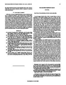
1. Introduction Recently, researches in the optical access network area have shown remarkable achievements since the advent of the passive optical network (PON) schemes. PON is the economic solutions allowing the service provider to share the cost of running fiber from the CO to the end users. Among the various solutions based on PON, a centralized light sources (CLS) approach has been proposed [1-3]. A CLS PON scheme has an advantage in that it can easily facilitate the wavelength management in the central office as well as reduce the cost of implementing the optical network unit (ONU) placing light sources only at the optical layer termination (OLT). Moreover, since we can assign a unique wavelength to each ONU or share a single wavelength among many ONUs’ with TDM switching and some appropriate scheduling processes, it turns out the CLS approach can accommodate smooth system upgrade from TDM-PON to WDM-PON in the future [4]. Although the CLS based optical access shows potential superiority for future access networks, field deployment is still limited by the infrastructure - the real coverage of the single mode fiber (SMF) in the local area, because most solutions assume SMF data link from OLT to ONU. While SMF shows high signal integrity in the long haul network, it is required to spend a large amount of time and cost to install SMF to the filed. On the other hand, multi mode fiber (MMF) is easy to install and it has been already installed on many campus or local area networks. Therefore, it would be better to include MMF into the optical access network. Despite the fact that the bandwidth-distance product is limited by the modal dispersion in MMF, there are several efforts to increase bandwidth-distance product. As a result, data transmission through a few kilometers at more than 1 gigabit per second is already achievable [5-7]. In this paper, we present, for the first time to our knowledge, a CLS access network including MMF. Using the physical mode confinement, the MMF link shows comparable performance to that of the SMF link. Results are verified using BER measurements. Considering the fact that the MMF is currently prevailing in the local area network, this architecture can expedite PON deployments. 2. Experiment, results and discussion As described in Figure 1, the network architecture follows the conventional frame of the CLS-based PON scheme [4]. In order to transmit a signal, a light source (distributed feedback (DFB) laser) is located at the OLT. Although the OLT supplies carrier to the all ONUs, since the incoming signal will decrease as it goes through the down stream link, we need an amplifier in the ONU to compensate power budget of the overall signal path. Therefore, each ONU has a semiconductor optical amplifier (SOA) and an intensity modulator to transmit the upstream signal. The upstream traffic passes through the same fiber link as the downstream link and arrives at the receiver in the OLT. In bi-directional transmission, it has been reported that the upstream signal can be more degraded than the downstream signal because the former is more exposed in the Rayleigh scattering [3]. Therefore, in our experiment we only investigate the worst case (upstream) due to space limitations.
1558 OTuC7.pdf
Fig. 1. Experiment set up. PC (polarization controller), MZ (Mach-Zehnder Modulator), VA (variable attenuator)
Generally, a passive splitter is located near the ONU in the PON access network. Hence, we can divide the whole data link into two segments. One is from the OLT to the splitter, and the other is from the splitter to the ONU. We place 15 km long SMF in the segment 1 and 1 km long MMF in the segment 2. The MMF has graded index and 50 µm core diameter. In order to connect to the single mode component, both ends of the MMF are core aligned and spliced with a small piece of SMF pigtailed by a conventional physical contact adaptor. Since we observe the performance of a single ONU, the passive splitter does not give a significant effect except contributing to the power budget. Therefore, we do not include the passive splitter in the experiment set up, instead using less SOA gain. Table 1 summarizes the loss of each component in the data link. Compared to an SMF of the same length, the MMF has additional 1.1 dB loss caused by the core misalignment between the SMF and the MMF connection as well as a higher order mode filtering at the interface from the MMF to the SMF connection. Table 1. Loss of components. System Component Loss (dB)
OLT Circulator 1.42
Segment 1(15km) SMF 3.1
Segment 2(1km) MMF SMF 2 0.9
Circulator 1.3
ONU PC 1
MZ 6
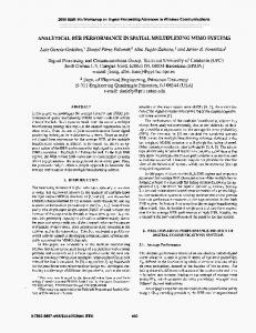
In order to create upstream data, the DFB laser in the OLT provides a continuous wave at 1550 nm that is remotely modulated at the ONU with NRZ coded, 2^23-1 pseudo random bit sequence (PRBS) at 1.25 Gbps through the intensity modulator. Overall power budget of the round trip signal path is 23.64 dB (before the 3 dB coupler). Therefore, we launch 2 dBm CW from the OLT and set the gain of SOA to 10 dB. The gain of SOA can be increased with the amount of the loss in the passive splitter, which depends on the number of ONUs. The received signal is coming from the isolator in the OLT and passing through optical attenuator (HP 8156A) and a power splitter. One branch of the power splitter goes into error analyzer (HP 70843A) after a SMF pigtailed commercially available photodiode, while the other is monitored by light wave multimeter (HP 8153A). As we vary the received power changing the value of optical attenuator, we measure bit-error-rate (BER) along the various received power for 3 separate cases. First, we measure a base line without fiber link, and then the measurement with SMF (15km) + MMF (1km) link is next. Replacing segment 2 with 1km long SMF, the third measurement is made. Comparing those 3 cases, we can clearly see the degree of difference caused by the MMF link. Figure 2 shows the results for 3 cases. Comparing the baseline to the case 3, there is 3 dB power penalty. Although we may ignore the effect of the chromatic dispersion for the 16 km long fiber link at 1.25 Gbps, the signal can be still affected by Rayleigh backscattering. Furthermore, there can be other noise sources, such as imperfect isolation of the circulators and noise coming from the SOA in the ONU. When we change the segment 2 to 1km long MMF, the signal can be degraded further due to the modal dispersion. However, since we launch the upstream signal with a polarization controlled, we can optimize the signal feasible to the upstream data link. With the finely tuned polarization control, we can achieve the BER performance up to 10-11 with the additional 2 dB power penalty compared to the case 3.
1558 OTuC7.pdf
The eye diagram for the case 2 at the low BER and high BER are shown in figure 3. As it can be seen in Figure 3, the top figure has a vague eye, and it becomes closed as time goes on, while we can see clear eye in the bottom. 1E-4
Back-to-Back SMF MMF
1E-5
Bit Error Rate
1E-6 1E-7 1E-8 1E-9 1E-10 1E-11 1E-12 -24
-23
-22
-21
-20
-19
-18
-17
-16
Received Power(dBm)
Fig. 2. BER measurement in the OLT
Fig. 3. Eye diagram of the signal in the SMF + MMF link. at BER of 10-5(top) and 10-11(bottom)
3. Conclusion In this paper, transmission performance in the SMF+MMF was presented using a promising access network configuration. Using core aligned connection and polarization control, we can achieve high BER performance with 2 dB more power penalty compared with the SMF link. Although a large portion of the link is still occupied by the SMF, considering the fact that the bandwidth-distance product of MMF keeps increasing these days, we can increase the length of the MMF link applying the same technique as in the previously investigated method. Therefore, the MMF can play an important role in the future optical access network. Reference [1] [2] [3] [4] [5] [6] [7]
N. J. Frigo, et al, “A wavelength-division multiplexed passive optical network with cost-shared components,” IEEE Photon. Technol. Lett., Vol. 6, no. 11, pp. 1365-1367, 1994. S. B. Tridandapani, B. Mukherjee, and G. Hallingstad, "Channel sharing in multihop WDM lightwave networks: do we need more channels?" IEEE/ACM Trans Networking. vol. 5, no. 5, Oct. 1997, pp. 71 9-27. J. Prat, C. Arellano, V. Polo, C. Bock, “Optical Network Unit Based on a Bidirectional Reflective Semiconductor Optical Amplifier for Fiber-to-the-Home Networks,” IEEE PHOTONICS TECHNOLOGY LETTERS, VOL. 17, NO. 1, Jan 2005, pp. 250-252. F.-T. An, K. S. Kim, D. Gutierrez, S. Yam, E. Hu, K. Shrikhande, and L. G. Kazovsky, “SUCCESS: A next-generation hybrid WD M/TDM optical access network architecture,” J. Lightwave Technol., vol. 22, no. 11, pp. 2557–2569, Nov. 2004. X. Zhao and F. S. Choa, “Demonstration of 10-Gb/s transmissions over 1.5-km-long multimode fiber using equalization techniques,” IEEE Photonics Technology Letters, vol. 14, no. 8, pp. 1187-1189, Aug. 2002. S. S-H. Yam, F-T. An, S. Sinha, M. E. Marhic and L. G. Kazovsky, “40 Gb/s Transmission over 140 m of 62.5 μm Multimode Fib er using Polarization-Controlled Launch”, presented at Conf. on Lasers and Electro-Optics, San Francisco, CA, May 16-20, 2004. T. Itoh, H. Fukuyama, S. Tsunashima, E. Yoshida, Y. Yamabayashi, M. Muraguchi, H. Toba and H. Sugahara, “1 km Transmission of 10 Gb/s Optical Signal over Legacy MMF using Mode-Limiting Transmission and Incoherent Light Source”, presented at Optical Fiber Commun. Conf., Anaheim, CA, March 6-11, 2005.