Aug 15, 2010 - of channels; e.g., digital subscriber lines and wireless local ... I. Rate-adaptive designs based on the maximization of the achievable information ...
On Improving the BER Performance of Rate-Adaptive Block Transceivers, with Applications to DMT Yanwu Ding, Timothy N. Davidson and K. Max Wong Department of Electrical and Computer Engineering, McMaster University, Hamilton, Ontario, Canada Abstract— We propose two strategies for improving the (uncoded) bit error rate (BER) performance of practical rateadaptive block-by-block communication schemes, such as discrete multitone modulation (DMT). Our strategies are inspired by some recent work which showed that for uniformly bit-loaded schemes, the transmission strategy which minimizes the BER for a linear receiver involves allocating power to the subchannels that are implicit in the block-by-block framework in a minimum mean square error (MMSE) fashion and linearly combining these subchannels using a normalized discrete Fourier transform (DFT) matrix. This combining equalizes the decision point signal-tonoise ratios (SNRs) of the subchannels. Given a non-uniformly bit-loaded scheme, our first design strategy simply performs a DFT-based linear combination within the groups of subchannels which share the same constellation. Our second strategy provides further reduction in the BER by re-allocating power within these groups in a MMSE fashion prior to DFT combining. Our examples indicate that our design strategies can provide significant reductions in the BER, and give rise to substantial SNR gains (of the order of several decibels).
I. I NTRODUCTION Block-by-block transmission schemes, such as orthogonal frequency division multiplexing (OFDM) and discrete multitone modulation (DMT), are popular schemes for efficiently and effectively transmitting data over diverse classes of channels; e.g., digital subscriber lines and wireless local area network channels. For applications in which a feedback channel from the receiver to the transmitter is available, and for channels which vary slowly, there are several mature design methods for (linear) block-by-block transceivers; see [1] for an insightful overview. A taxonomy of these methods reveals three dominant classes: I. Rate-adaptive designs based on the maximization of the achievable information rate, subject to a bound on the transmitted power; e.g., water-filling based DMT [2–4]. II. Performance orientated designs based on maximizing a measure of the fidelity of (a linearly processed version of) the received block, subject to a bound on the transmitted power; e.g., minimum mean square error (MMSE) [5–8]; maximum signal-to-noise ratio (SNR) [7]; and minimum (uncoded) bit error rate (BER) [1], [9–11]. III. Constraint satisfaction designs based on minimizing the transmitted power required to achieve a given fidelity at a given rate; e.g., margin adaptive designs [3], [12].
GLOBECOM 2003
A unifying feature of these three design classes is that the structure of the optimal (linear) transmitter-receiver pair diagonalizes the appropriate channel matrix, and hence exposes a set of parallel subchannels for communication. The classes are differentiated by the way in which the transmission power and the bits to be transmitted are allocated to these subchannels, and the way in which the parallel subchannels are (linearly) combined by the transmitter. The standard transmitter design techniques obtain optimal performance (for the given criterion) without combining the subchannels. However, it has recently been shown [1], [10], [11] that achieving the minimum BER of a uniformly bit-loaded scheme with linear equalization and symbol-by-symbol detection requires linear combination of the subchannels with a special class of unitary matrices; see Section III. The rate-adaptive designs of Class I are usually derived from the fact that the capacity of a block-by-block transmission system can be achieved if the appropriate channel matrix is diagonalized and power is allocated to the subchannels according to the water-filling distribution [2]. Unfortunately, achieving this capacity involves the implementation of ideal Gaussian codes—a rather awkward task in practice. Standard practical rate-adaptive designs achieve (reasonably) reliable transmission at rates which are a significant fraction of the capacity by employing members of standard constellation and code families on each subchannel. The goal of this paper is to apply some of the principles of the minimum BER designs from Class II to improve the BER of standard rateadaptive designs from Class I. The key observation is that once the constellation for each subchannel has been determined, the work in [1], [10], [11] indicates that the BER can be improved by re-allocating power among those subchannels which share the same constellation and by linearly combining these subchannels. We will demonstrate in our examples that the resulting reduction in the BER can be quite significant, and can give rise to substantial SNR gains (of the order of several decibels). Our development is based on uncoded error rates for systems with linear equalization and symbolby-symbol (i.e., parallel) detection. However, we will observe that our design approach equalizes (and maximizes) the decision point SNRs of each set of subchannels which have the same constellation. This fact has the potential to significantly
- 1654 -
0-7803-7974-8/03/$17.00 © 2003 IEEE
Authorized licensed use limited to: McMaster University. Downloaded on August 15,2010 at 18:32:32 UTC from IEEE Xplore. Restrictions apply.
v s
F
u
H
+
r
sˆ 1
G
sˆ m sˆ M
the mth subchannel is � � �� SNRm bm = log2 1 + , Γ
Detector Detector Detector
Fig. 1. Generic block-by-block transmission system with symbol-by-symbol (parallel) detection.
simplify the design of appropriate coding schemes, especially when ‘hard-decision’ decoding is employed. Before we present our results, we point out that while this paper was being prepared we discovered that the principles of some methods from Class III had been independently applied [12] to reduce the power required to achieve a given quality of service at the rates determined by standard rate-adaptive designs. While the technical details of the work in [12] and that herein are quite similar, the design objectives are complementary but somewhat different. II. L INEAR BLOCK - BY- BLOCK TRANSMISSION In this paper we consider linear block-by-block transmission schemes of the form in Fig 1. The transmitter (precoder) linearly transforms a block of M data symbols s into a block of P ≥ M channel symbols u = F s. For each transmitted block, the receiver collects a block of N ≥ M samples r, ˆ = Gr of s are linearly obtained. from which the estimates s These estimates can be written as sˆ = GHF s + Gv,
(1)
where H is the N × P (equivalent) channel matrix, and v denotes the zero-mean Gaussian receiver noise, which has a covariance matrix Rvv . The model in Fig 1 and Eq. (1) is quite flexible. In particular, it covers both zero-padded and cyclicprefixed transmission over both single and multiple antenna frequency-selective channels. For brevity, we will focus on systems with zero-forcing equalization in this paper, and will exploit the results in [10] for minimum BER precoding for zero-forcing equalization. However, the principles of our designs can be directly extended to systems with minimum MSE equalization by exploiting results in [1], [11]; see [12] for a related approach. If zero-forcing equalization is employed, G = (HF )† , where (·)† denotes the pseudo-inverse. Assuming that HF has full column rank, Eq. (1) becomes sˆ = s + Gv.
(2)
A standard simple way to design a practical rate-adaptive transmission scheme is to constrain each element of the signal vector s to come from a member of the family of I–ary QAM constellations. The order of the QAM constellation used on each subchannel is typically chosen according to the decision point SNR. If the elements of s are uncorrelated1 , then a simple way to choose the number of bits to be assigned to 1 If s is correlated, then the data vectors can be pre-whitened, so long as the covariance matrix of s has full rank.
GLOBECOM 2003
(3)
where �·� denotes the greatest integer ≤ x, Γ is the so-called SNR gap [3] which reflects the desired uncoded error rate performance, and SNRm is the decision-point signal-to-noise ratio of the mth subchannel. (If Γ > 2, the ‘floor’ operation in (3) is often replaced by a rounding operation.) If each element of s is scaled so that Rss = E{ssH } = Es I (the elements of s have already been assumed to be uncorrelated), then for the zero-forcing equalized scheme in (2) SNRm =
Es Es = , � �H H † [GRvv G ]mm [(HF ) Rvv (HF )† ]mm (4)
where [·]ij denotes the (i, j)th element of a matrix. Since the subchannel SNR in (4) depends on the precoder, jointly optimal bit-loading/precoder pairs can be rather awkward to obtain directly. However, effective designs can be obtained in a straightforward manner by designing the precoder via waterfilling and then assigning bits to the subchannels according to (3). For simplicity, we will focus on such a power loading algorithm in this paper. However, the principles of our approach are essentially independent of the manner in which bm is determined, and hence our approach is also applicable to systems designed via standard bit loading algorithms [3]. If the mth element of s is selected from a Gray-coded square QAM constellation of order 2bm , where bm is even, then the average probability of error for the scheme in (2) is closely approximated by [13]2 �√ � � M 2bm − 1 3SNRm 2 � √ Pe ≈ erfc M m=1 bm 2bm 2(2bm − 1) √ � �
2bm − 2 3SNRm √ erfc 3 + , (5) 2(2bm − 1) bm 2bm �∞ 2 where erfc(x) = √2π x e−t dt. In what follows it will be convenient for us to permute the elements of s so that the symbols from the same constellation are grouped together. To describe that grouping, let K denote the number of distinct constellations used, let ˜bi , i = 1, 2, . . . , K, denote the number of bits in the ith distinct constellation, and let Gi denote the set of subchannels in the ith group; i.e., Gi = {m|bm = ˜bi }. Using that notation, Eq. (5) can be rewritten as � � � K βi 2 � � αi erfc Pe ≈ M i=1 [GRvv GH ]mm m∈Gi � �
βi + ζi erfc 3 , (6) [GRvv GH ]mm 2 A related formula applies for rectangular QAM constellations [13], but for brevity we only include the square case. Furthermore, although we will use (5), the principles of our approach remain valid when we use the simpler (and more common) approximation of Pe in which the second component of the summand in (5) is deemed negligible.
- 1655 -
0-7803-7974-8/03/$17.00 © 2003 IEEE
Authorized licensed use limited to: McMaster University. Downloaded on August 15,2010 at 18:32:32 UTC from IEEE Xplore. Restrictions apply.
√ where αi =
˜ bi
˜
b 2 √i −1 ˜ 2b i
, βi =
3Es , ˜ 2(2bi −1)
√ and ζi =
˜ bi
˜
b 2 √i −2 ˜
2b i
.
A key component in� our design approach is the observation � a with a > 0 is convex in 0 < that the function erfc x x < 2a . Hence, the summand of m ∈ Gi in (6) is a convex 3 H function of [GRvv G ]mm so long as [GRvv GH ]mm < 2β3 i . If the bit loading is performed via (3), then for all m ∈ Gi , Es i = 2β [GRvv GH ]mm ≤ ˜ 3Γ , and hence the summand of Γ(2bi −1) √ m ∈ Gi in (6) is convex for all m and i. (If Γ > 1/( 2 − 1) then the summand of m ∈ Gi in (6) remains convex when the rounding function replaces the floor function in (3).) Therefore, we can apply Jensen’s inequality [2] to (6) to obtain the following lower bound on the average bit error rate, � � � K βi Mi 2 � Mi αi erfc Pe ≥
H M i=1 m∈Gi [GRvv G ]mm � �
βi Mi + ζi erfc 3 H m∈Gi [GRvv G ]mm K
2 �¯ Pe,i M i=1 = P¯e , =
(7)
where Mi is the number of subchannels in the ith group (i.e., the cardinality of Gi ), and the definition of P¯e,i is implicit. In the following section we will exploit results in [10] to show how once the bit loading has been established, the lower bound in (7) can be achieved by linearly combining the subchannels within each group with a unitary matrix whose elements have equal magnitude; e.g., a normalized DFT matrix (see Design A). Furthermore, we will show how the power allocation among the subchannels in each group can be modified to reduce the lower bound P¯e . This reduced lower bound can also be achieved by linearly combining the subchannels in the group with a normalized DFT matrix (see Design B). In both Designs A and B the linear combining of the subchannels has the desirable effect of making the decision point SNRs of each subchannel in the same group equal. III. N EW PRECODER DESIGNS As we mentioned in Section II, our design approach is essentially independent of the manner in which the constellation for each subchannel is chosen. However, the standard water-filling based rate-adaptive schemes have many desirable properties. Here we will use the simple scheme in (3). For the block transmission system in (1), the precoder F which maximizes the achievable information rate subject to a transmission power budget tr(F Rss F H ) = Es tr(F F H ) ≤ Es p0 is (e.g., [2]) F WF = W ∆WF ,
(8)
where W ΛW H is an eigenvalue decomposition of H H R−1 vv H, and hence the matrix W ‘exposes’ the (eigen) subchannels of the system. The diagonal matrix ∆WF
GLOBECOM 2003
is the water-filling power loading matrix. Its mth diagonal element is δWF,m ≥ 0, where 2 δWF ,m = max{γ − Γ/(Es λm ), 0}.
(9)
Here, λ m is the mth diagonal element of Λ, and γ is chosen 2 so that m δWF ,m = p0 . The decision point SNR for the mth subchannel for this precoder is 2 SNRWF,m = Es δWF ,m λm .
(10)
In the design of our modified precoders below, we consider precoders of the form F = W ∆Q,
(11)
where W was defined after (8), ∆ is a diagonal power loading matrix, and Q is a structured unitary matrix which can be chosen to linearly combine the subchannels which employ the same constellation. To describe the structure of Q, let P denote a permutation matrix that groups together the elements employ the same constellation; i.e., for
i−1 of s that i ˜ = P s all s]q of s q ∈ ( j=1 Mj , j=1 Mj ] the elements [˜ ˜ bi come from the same 2 –ary QAM constellation. The matrix Q takes the form Q = P T U P , where U is a block diagonal matrix whose ith block is a square unitary matrix of dimension Mi , 1 ≤ i ≤ K; i.e., U = blkdiag{U 1 , U 2 , . . . , U K }. ˜ P , where ∆ ˜ = Observe that F = W ∆P T U P = W P T ∆U T P ∆P is the power loading matrix when the subchannels are grouped according to their assigned constellations. To ˜ i denote the ith diagonal block simplify the notation, we let ∆ T ˜ of ∆ = P ∆P , where the blocks are of size Mi , and let ˜ i denote the ith diagonal block of Λ ˜ = P ΛP T . We now Λ proceed with our designs. A. Design A: Subchannel combining In this design we choose ∆ = ∆WF , and hence our only degree of freedom is the block diagonal unitary matrix U ; i.e., F A = W ∆WF P T U P . If we let GA = (HF A )† , then for each symbol in each group which is allocated bits (i.e., for which ˜bi > 0), the decision point SNR of the mth subchannel is Es Es = (12) SNRA,m = H H [GA Rvv GA ]mm [U i Θi U i ]�� where m ∈ Gi , and �, 1 ≤ � ≤ Mi , is the position of the mth symbol within that group (as determined by P ). Here, ˜ −1 Λ ˜ −1 ∆ ˜ −1 , where Λ ˜ i and ∆ ˜ i are guaranteed to be Θi = ∆ i i i ˜ i is singular, then ˜bi = 0, invertible if ˜bi > 0. (Note that if Λ according to (3).) Since each U i is unitary, for any subchannel in the ith group, m ∈ Gi , min SNRWF,m ≤ SNRA,m ≤ max SNRWF,m ,
m∈Gi
m∈Gi
(13)
where SNRWF,m is the decision point SNR on the mth subchannel of the water filling precoder. Equation (13) shows that for any U i , the decision point SNR of subchannel m ∈ Gi for Design A lies between the largest and smallest SNRs achieved by the subcarriers from the same group in the water-filling
- 1656 -
0-7803-7974-8/03/$17.00 © 2003 IEEE
Authorized licensed use limited to: McMaster University. Downloaded on August 15,2010 at 18:32:32 UTC from IEEE Xplore. Restrictions apply.
design. Hence, the bit loading determined for the water-filling precoder via (3) remains valid for Design A. Now, since U i is unitary, the lower bound, P¯e,i , on the BER of the ith group for the water-filling design remains valid for Design A. What remains to be shown is that this lower bound can be achieved by specific choices of U i . Using Jensen’s inequality [2], we observe that P¯e,i is achieved if all the decision point SNRs in the ith group are equal. Using an argument similar to that in [10], these SNRs can be made equal by choosing U i to be a normalized Mi × Mi discrete Fourier transform (DFT) matrix, D Mi . Therefore, the precoder F A = W ∆WF P T blkdiag{D M1 , D M2 , . . . , D MK }P (14) is guaranteed to have a lower (uncoded) BER than the waterfilling precoder. B. Design B: Power re-allocation and subchannel combining Design A achieves the lower bound in (7) on the BER of the water-filling based design. However, this lower bound can be reduced by re-allocating power among the subchannels in each group. Furthermore, this reduced lower bound is also achievable. Deriving such a precoder involves the design of both ∆ and U in (11). The role of ∆ is to reduce P¯e while ensuring that power allocated to each group of subchannels remains the same as it was for the water-filling design. This constraint ensures that the original bit loading continues to satisfy (3) with the original SNR gap. Using the work in [10], the lower bound on the group BER, P¯e,i , is minimized if the power loading over the ith group is the minimum mean square error (MMSE) power loading for that group (and zeroforcing equalization) subject to the total power allocated to that group remaining the same as the water-filling design. So long as ˜bi > 0, the appropriate MMSE power loading ˜ B,i = φi Λ ˜ −1/4 , where φi > 0 satisfies for group i is ∆ i 2 ˜ ˜ −1/2 ). The scalar φi ensures that )/ trace( Λ φ2i = trace(∆ WF,i i the total power allocated to the ith group is the same as it was for the water-filling design. As shown in the Appendix, for any subchannel in the ith group (i.e., m ∈ Gi ), a relationship analogous to (13) holds: min SNRWF,m ≤ SNRB,m ≤ max SNRWF,m .
m∈Gi
m∈Gi
(15)
Hence, the original bit loading continues to satisfy (3) under the modified power loading scheme. ˜ B,i , minimizes Since the modified group power loading, ∆ ¯ ¯ Pe,i , the lower bound Pe on the total BER is lower for Design B than it was for Design A and the water-filling design. Moreover, using an analogous argument to that for Design A, this reduced lower bound on the BER is achieved by choosing U i = D Mi . That is, the reduced lower bound on the BER is achieved by the following precoder: F B = W ΦΛ−1/4 P T blkdiag{D M1 , D M2 , . . . , D MK }P , (16) ˜ and where Φ = P T ΦP ˜ = blkdiag{φ1 I M , φ2 I M , . . . , φK I M }. Φ 1
2
K
Here, for brevity, we have assumed that ˜bi > 0 for all i.
GLOBECOM 2003
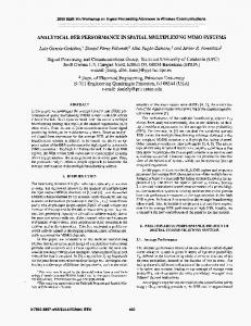
IV. P ERFORMANCE ANALYSIS In this section, we compare the BER performance of our Designs A and B to that of the underlying water-filling based rateadaptive design in a simple single-antenna discrete multitone system. In this case, W is a normalized inverse DFT matrix. The noise on each subcarrier is assumed to be Gaussian, zero mean, and independent from that on the other subcarriers (as is often assumed in standard DMT designs). Therefore, the 2 , where mth diagonal element of Λ is |H(ej2π(m−1)/M )|2 /σm jω 2 H(e ) is the frequency response of the channel, and σm is the noise variance on the mth subcarrier. The particular DMT scheme that we will consider has M = 32 subcarriers, and a cyclic prefix of length 4. Hence, P = 36 is the transmitted block size. The noise is modelled as being white; 2 = σ 2 . To determine the bit loading, we applied (3) i.e., σm to the water-filling power loaded precoder with Γ = 8 dB and with a rounding operation replacing the floor operation in (3). For simplicity of implementation, we restricted our attention to square QAM constellations, so bm was always even. In Fig. 2, we provide the BER performance of our precoders and the water-filling precoder averaged over 1000 realizations of a frequency-selective Rayleigh fading channel of length 5. (The channel taps were generated independently from a circular complex Gaussian distribution of variance 0.5 per dimension.) The block SNR is defined as Es p0 /(M σ 2 ), which is equal to the average symbol SNR. Since we are performing a rateadaptive design, as the block SNR increases the number of bits transmitted per block also increases. For each realization of the channel, all three precoders transmit the same number of bits for each subcarrier and hence the same number of bits per block. The number of bits per transmitted block at each SNR, averaged over the randomly generated channels is shown in Fig. 3. As predicted by our derivations, Fig 2 illustrates the fact that Design A provides a lower BER than the underlying water-filling design, and that Design B provides a further improvement in the BER. At various points on these BER curves the SNR gain of Design A over the water-filling design is around 12 to 15 dB. Design B provides an additional SNR gain of around 2 to 3 dB. V. C ONCLUSION We have provided two strategies for improving the (uncoded) BER of rate-adaptive block-by-block communication schemes. These strategies were based on extending recent results on minimum BER transmission for uniformly bit loaded schemes [1], [10], [11] to the case of non-uniform bit loading. The resulting precoders involve a DFT-based linear combination of the subchannels which share the same constellation. In the case of the second strategy, a re-allocation of power across these subchannels in a minimum mean square error sense is also performed. Our precoders have the rather appealing property that they equalize the decision point SNRs of those subchannels which share the same constellation. The examples indicated that our precoders can provide significant reductions in the BER and can give rise to substantial SNR
- 1657 -
0-7803-7974-8/03/$17.00 © 2003 IEEE
Authorized licensed use limited to: McMaster University. Downloaded on August 15,2010 at 18:32:32 UTC from IEEE Xplore. Restrictions apply.
A PPENDIX D ERIVATION OF (15)
WF Design A Design B
If we let xm = [Λ−1 ]mm and ym = [∆2WF ]mm , then if subchannel m is a member of the ith group (and ˜bi > 0),
�1/2 1/2 � m∈Gi xm H
[GB Rvv GB ]mm ≥ min xm m∈Gi m∈Gi ym � �1/2 Mi (minm∈Gi xm )1/2 ≥ min xm m∈Gi Mi maxm∈Gi ym xm = min m∈Gi ym = min [GWF Rvv GH WF ]mm ,
−3
BER
10
m∈Gi
−4
10
5
10
15
20
25
30
Block SNR
Fig. 2. Average BER performance of the three precoders for the system described in Section IV.
300
250
bits per block
200
150
100
50
0
5
10
15
20
25
30
Block SNR
Fig. 3. Number of bits transmitted per block in Fig. 2, averaged over the 1000 realizations of the channel. Recall that each precoder transmits the same number of bits.
gains (of the order of several decibels). Since our precoders have a simple structured closed form expression (viz. Eqs (14) and (16)), they are also relatively simple to implement in practice.
and hence the right inequality in (15). The inequality on the left of (15) can be derived in an analogous fashion. R EFERENCES [1] D. P. Palomar, J. M. Cioffi, and M. A. Lagunas, “Joint Tx–Rx beamforming design for multicarrier MIMO channels: A unified framework for convex optimization,” IEEE Trans. Signal Processing, vol. 51, no. 9, pp. 2381–2401, Sept. 2003. [2] T. M. Cover and J. A. Thomas, Elements of Information Theory. New York: Wiley, 1991. [3] T. Starr, J. M. Cioffi, and P. J. Silverman, Understanding Digital Subscriber Line Technology. Upper Saddle River, NJ: Prentice Hall, 1999. [4] A. Scaglione, S. Barbarossa, and G. B. Giannakis, “Filterbank transceivers optimizing information rate in block transmissions over dispersive channels,” IEEE Trans. Inform. Theory, vol. 45, no. 3, pp. 1019–1032, Apr. 1999. [5] J. Salz, “Digital transmission over cross-coupled linear channels,” AT&T Tech. J., vol. 64, no. 6, pp. 1147–1159, July–Aug. 1985. [6] J. Yang and S. Roy, “On joint transmitter and receiver optimization for multiple-input-multiple-output (MIMO) transmission systems,” IEEE Trans. Commun., vol. 42, pp. 3221–3231, Dec. 1994. [7] A. Scaglione, G. B. Giannakis, and S. Barbarossa, “Redundant filterbank precoders and equalizers Part I: Unification and optimal designs,” IEEE Trans. Signal Processing, vol. 47, no. 7, pp. 1988–2006, July 1999. [8] A. Scaglione, P. Stoica, S. Barbarossa, G. B. Giannakis, and H. Sampath, “Optimal designs for space-time linear precoders and decoders,” IEEE Trans. Signal Processing, vol. 50, no. 5, pp. 1051–1064, May 2002. [9] L. Goldfield, V. Lyandres, and D. Wulich, “Minimum BER power loading for OFDM in fading channel,” IEEE Trans. Commun., vol. 50, no. 11, pp. 1729–1733, Nov. 2002. [10] Y. Ding, T. N. Davidson, Z.-Q. Luo, and K. M. Wong, “Minimum BER block precoders for zero-forcing equalization,” IEEE Trans. Signal Processing, vol. 51, no. 9, pp. 2410–2423, Sept. 2003. [11] S. S. Chan, T. N. Davidson, and K. M. Wong, “Asymptotically minimum bit error rate block precoders for minimum mean square error equalization,” in Proceedings of the Second IEEE Sensor Array and Multichannel Signal Processing Workshop, Rosslyn, VA, USA, Aug. 2002. [12] D. P. Palomar, M. A. Lagunas, and J. M. Cioffi, “Optimum linear joint transmit-receive processing for MIMO channels with QoS constraints,” IEEE Trans. Signal Processing, 2003, to appear. Also: in Proc. 36th Asilomar Conf. Signals, Systems, Computers, Pacific Grove CA, Nov. 2002. [13] K. Cho and D. Yoon, “On the general BER expression of one and two dimensional amplitude modulations,” IEEE Trans. Commun., vol. 50, no. 7, pp. 1074–1080, July 2002.
For simplicity, the focus of this paper was on block-by-block schemes with linear zero-forcing equalization. However, the principles behind our design extend immediately to the case of MMSE equalization [1], [11]. Some independent complementary work in that direction appeared recently in [12].
GLOBECOM 2003
- 1658 -
0-7803-7974-8/03/$17.00 © 2003 IEEE
Authorized licensed use limited to: McMaster University. Downloaded on August 15,2010 at 18:32:32 UTC from IEEE Xplore. Restrictions apply.