BEYOND INTERFACE BUILDERS: MODEL-BASED INTERFACE TOOLS Pedro Szekely, Ping Luo and Robert Neches USC/Information Sciences Institute 4676 Admiralty Way Marina del Rey, CA 90292 (310) 822-1511 E-mail:
[email protected],
[email protected],
[email protected] ABSTRACT
Interface builders only support the construction of the menus and dialogue boxes of an application. They do not support the construction of interfaces of many application classes (visualization, simulation, command and control, domain-specific editors) because of the dynamic and complex information that these applications process. HUMANOID is a model-based interface design and construction tool where interfaces are specified by building a declarative description (model) of their presentation and behavior. H UMANOID’s modeling language provides simple abstraction, iteration and conditional constructs to model the interface features of these application classes. HUMANOID provides an easy-touse designer’s interface that lets designers build complex interfaces without programming.
by the user (specialized editors). 4. Time varying data. Applications often process data that changes at run-time (command and control, simulation), or allow users to change the data (specialized editors). These applications typically show several views of the data, which must be kept coordinated and up-to-date.
KEYWORDS: UIMS, Design Process, Interface Builders,
Model-Based Interface Tools. INTRODUCTION
Most tools for interface construction support the construction of the menus and dialogue boxes of an application, but provide little or no support for constructing the main application displays that show application-specific objects and let end-users manipulate those objects. Most applications have interface requirements that go far beyond the menus and dialogue boxes that can be constructed using interface builders: 1. Data with complex structure. Most visualization applications (e.g., TreeViz [3]) visualize complex data structures with arbitrary levels of nesting. 2. Heterogeneous data. Applications typically process several kinds of data (different types of notes in a music editor, different kinds of shapes in a drawing editor), which require different presentations, and which require different input behaviors for convenient manipulation. 3. Variable amounts of data. Applications typically process variable amounts of data that could come from data bases or other programs (visualization, command and control, simulation) or data constructed interactively
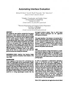
Figure 1. TreeViz, a visualization tool for hierarchical information (left), and the portions of that interface that can be constructed using interface builders (right).
Figure 1. illustrates the main shortcoming of most interface building tools. The left hand side of the figure shows the display of TreeViz [3], a simple visualization application for visualizing hierarchical data. In this example, TreeViz is visualizing the cost to maintain the computers in an organization. The shapes represent different classes of members of the organization, the shading represents different kinds of computer, and the size of the areas represents the cost to maintain the computer. The right hand side of the figure shows the portions of this interface that can be specified using an interface builder. If interface builders do not support the construction of the interface for even a simple application such as TreeViz, much less do they support the interface for the application classes mentioned above. The TreeViz display cannot be specified with an interface builder because the number of objects shown varies at run-time, the shape and shading of the objects depend on attributes of the data, and the layout is recursively defined. The challenge for interface construction tools is to embody them with a richer and more expressive model of interfaces, while making them intuitive and easy to use for designers. Interface builders do not meet this challenge. They are intuitive and easy to use, but are not expressive enough. This paper describes a tool called HUMANOID that meets
this challenge. The HU M A N O I D modeling language supports the specification of most aspects of an interface (presentation, behavior and dialogue). The main contribution of H U M A N O I D lies in the nature of the modeling language and the way in which it is delivered to designers in an intuitive and easy-to-use interface. H U M A N O I D ’s modeling language has abstraction, composition, iteration and conditional constructs designed to support the modeling of interfaces with the characteristics mentioned above (numbered 1-4). The abstraction mechanism allows the specification of presentation templates to present all the instances of a class of objects, and behavior templates to specify how the presented objects can be manipulated. The composition construct allows presentation templates to be composed in order to define the presentation of data with complex structure (1). The conditional constructs support the presentation of heterogeneous data (2). Coupled with the iteration construct, the abstraction and composition constructs allow the specification of presentations of variable amounts of heterogeneous data (3). Finally, the modeling language uses a data-dependency mechanism similar to spreadsheet formulas to specify the dependencies between data and presentations in order to support automatic presentation update of time varying data (4). This paper is organized as follows. The next section presents an overview of HUMANOID’s modeling language and the desiderata for the designer’s interface, followed by a related work section. The body of the paper discusses the main constructs of the modeling language, the designer’s interface facilities for using the modeling constructs, and shows how to construct the TreeViz interface from scratch. The paper closes with current status and conclusions.
HUMANOID OVERVIEW H UMANOID is a model-based system.
Interfaces are specified by constructing a declarative model of how the interface should look and behave. A standard run-time support module is included in every application to execute the model, that is, to construct the application displays and interpret input according to the information in the model. The Humanoid Modeling Language HUMANOID provides a declarative modeling language that
factors the design of interfaces into five semi-independent dimensions [12]: 1. Application semantics: represents the objects and operations of an application. The application semantics defines the domain of discourse of the interface, and is referenced by the dimensions of the model that define the presentation, behavior and dialogue sequencing of the interface. 2. Presentation: defines the visual appearance of the interface. 3. Behavior: defines the input gestures (e.g. mouse clicks) that can be applied to presented objects, and their effects on the state of the application and the interface. 4. Dialogue sequencing: defines the ordering constraints for executing commands and supplying inputs to commands. 5. Action side-effects: defines actions executed automatically when commands or command inputs change state (e.g., making a newly created object the current selection). Only the first three dimensions will be discussed in detail in this paper. Details on the last two appear elsewhere [12]. The Designer’s Interface to Humanoid The designer’s interface to HUMANOID supports a very tight
design/evaluate/redesign cycle. The typical screen of a designer’s workstation (Figure 2.) contains windows showing different views of the design model (windows labeled Part Editor, Presentation Template
Figure 2. Snapshot of a screen showing a typical configuration of windows during a design session with Humanoid.
Structure and Layout Editor), windows showing the application data structures (Object Browser), and windows showing the interfaces that HUMANOID generates from the model (TreeViz). These windows are explained in more detail later in the paper. The designer’s interface was designed according to the following desiderata:
greatly facilitates the programming of graphical editors, the task still requires extensive programming skills. The usability dimension generally goes in the opposite direction. Low expressivity tools like interface builders are easy to use, and high expressivity tools like programming languages or object-oriented frameworks are hard to use. Demonstrational Tools
All features of the design should be visible and changeable by designers so that designers can control all aspects of an interface design. Example interfaces are editable views of the model. HUMANOID capitalizes on the idea that people understand problems better when they can interact both with a symbolic representation and with illustrative examples of it [15]. So, HUMANOID shows designers views of the model (symbolic representation) and interfaces generated from the model (examples). Designers can refine the model by editing the example interfaces produced from the model. All views of the design are linked together to help designers understand and edit the model. This requirement manifests itself in several features of HUMANOID. • H UMANOID provides facilities to map from example features to model elements and vice-versa. Designers can point to an element of the design, and ask HUMANOID to highlight the portions of the example displays that it controls. Conversely, designers can point to a feature of an example display and ask to see the portions of the model that generated it. • All example interfaces are kept up-to-date after every modification to the design model (even if the design is not fully specified), helping designers to immediately see the consequences of their modeling decisions. Conversely, when designers perform a refinement by demonstration they can immediately see HUMANOID’s interpretation of the example in one of the design views. RELATED WORK
Interface design and construction tools can be compared along expressivity and usability dimensions. The expressivity dimension defines the class of interfaces that can be specified, where as the usability dimension captures the level of expertise that designers need to use the tool. At the low end of the expressivity spectrum are interface builders [9], with essentially a single modeling construct: instantiation. Designers can create instances of a predefined set of classes of interface building blocks, and set the values of their parameters. Interface builders can only be used to specify the menus and dialogue boxes of an application, but not the main application displays. At the high end of the expressivity spectrum are programming languages, which allow programmers to create arbitrarily sophisticated interfaces by writing programs (procedural models of interfaces). Close to the programming end of the spectrum are object-oriented systems like Unidraw [13] which provide classes for building specific kinds interfaces. Even though Unidraw
Demonstrational tools such as Lapidary [5] and Druid [10] are an attempt to move up the expressivity spectrum while remaining in the high end of the usability spectrum. Lapidary, for instance, lets designers demonstrate examples of a boxes and arrows application where the arrows should remain attached to the boxes, and constructs “box” and “arrow” classes with the appropriate constraints so that instances remain connected. The generalizations that demonstrational tools make are typically not shown to designers. In the cases where designers can view the generalizations (e.g. Lapidary), there are no tools to help designers understand the relationship between features of the examples and features of the generalizations. Hence, designers find it hard to understand the generalizations. H UMANOID differs from these tools in that the model (generalizations) plays a primary role. The demonstrational capabilities of HUMANOID are weak compared to Lapidary and Druid, but HUMANOID derives its strength from its modeling power, and the combination of explicit model and example views to construct the models. Other Model-Based Approaches
Most model-based systems score high in expressivity, but low in usability. UIDE [2] is a model-based interface tool whose application and dialogue sequencing models are similar to HUMANOID’s, but whose presentation model is relatively impoverished compared to HUMANOID’s. UIDE does not have a sophisticated designer’s interface so its usability is low. UIDE’s approach to usability is automation. The richness of UIDE’s model enables the construction of tools like Cartoonist [11] that generates animated help, and DON that generates dialogue boxes [4]. UIDE emphasizes model analysis tools such as consistency checkers [1] and keystroke analysis [2]. Since HUMANOID’s and UIDE’s models are similar, the complementary advantages of both systems could be integrated in a single tool. ITS [14] can also be characterized as a model-based system. ITS has a presentation model similar to HUMANOID’s, but its dialogue and application models are less expressive. ITS does not score high in usability due to its textual specification language, but it is a production quality system. Having reviewed related work, we now focus on how HUMANOID’s modeling language and designer’s interface are used to build interfaces. APPLICATION MODEL
The first step in designing an interface is to model the application functionality, i.e., the objects and the commands
that the application provides. In HUMANOID , these are formally modeled in an object-oriented way, by specifying the types and slots of each object. Commands are modeled by specifying their inputs, preconditions, and a call-back procedure. Other more advanced features of the application model are discussed elsewhere [12].
designers to express “hidden” notions, such as the EDIT command and the dialogue sequencing constraints. • The application model can also be used by automated design critics and automatic help generation tools as illustrated by the UIDE system [1,2,4,11]. After having defined an initial version of the application model, the designer can proceed to refine the default interface to specify the presentation and behavior of the main application area or to fine-tune the default interface. The next sections describe the refinement process that HUMANOID supports. If we were using an interface builder, we would proceed to drop into a programming language, because the interface builder support ends when the construction of the main application areas starts.
Figure 3. The application model of TreeViz.
Figure 3. shows the TreeViz application model. To start off the design we decided that there should be a Q U I T command, and an EDIT command to edit the information contained in any record in the hierarchy. There is an input ROOT-OBJECT to store the root record of the hierarchy to be shown. We made the dialogue sequencing decision that there should be a notion of current selection, and that the EDIT command edits the current selection. Accordingly, we defined another global input called CURRENT-OBJECT, and tied the OBJECT-TO-EDIT input of the E D I T command to CURRENT-OBJECT. We also made a presentation decision by stating that QUIT belongs to the PANEL COMMANDS group, which tells HUMANOID which commands to present as a panel of command buttons. If we were using an interface builder we would have started the design of the interface differently. We would have drawn a QUIT button at the bottom of the screen, and tied it to a callback procedure. We would have drawn the RECORD and COST labels at the top of the screen, but would not have been able to tie them to anything (Figure 1, right). This is all that we could have done using an interface builder. As mentioned above, the main display of TreeViz cannot be specified using interface builders. We would not have been able to specify the EDIT command because we want a “double click” over the display area showing a record, rather than a screen button to invoke it. Interface builders have no provisions for such invisible behaviors. The application model has several advantages over the interface builder approach: • HUMANOID generates a default interface for an application from the application model. This default interface is very similar to the one constructed with an interface builder. It contains a menu-bar, an input panel, a blank area for the main application area, and a command panel at the bottom. In addition, HUMANOID provides facilities to customize the layout and other aspects of the interface to make it look as desired. • The application model makes all aspects of the design visible, where as interface builders only allow designers to talk about elements that have an explicit representation on the end-user’s interface. The application model allows
PRESENTATION TEMPLATES In HUMANOID , designers model the presentation of an
application incrementally. They first identify the major elements of the display and define presentation templates for them, which initially are just names for the display elements. Designers then proceed to define the characteristics of each display element, such as the data it presents, its parts, and its layout. For example, in TreeViz we see that the display is composed of three major elements: shapes (rectangles, ovals, etc.), columns and rows (Figure 1), so we proceed to define presentation templates for them called TreeViz-Shape, TreeViz-Column and TreeViz-Row (Figure 4). A presentation template is an abstraction to model the characteristics of display elements. At run-time presentation templates are used as rubber-stamps to create as many instances of a display element as needed. Presentation templates represent the following information: • Is-A: a presentation template can be defined as a refinement of an existing template, by modifying any of the attributes listed below. • Input data: the type of information that can be displayed using a presentation template. • Widget: the graphical object produced by a presentation template. It can be a primitive graphical object (line, icon, text, etc.) a toolkit primitive (menu, button, etc.), or a layout management widget (column, row, table, graph, etc.) • Applicability conditions: predicates identifying the contexts where the template is appropriate. • Parts: the decomposition of a complex display into simpler displays. Each part is modeled in terms of the input data it ought to present, and a default template for presenting the data. HU M A N O I D uses that default template as a starting point for a search for the most appropriate template to display the part, based on the applicability conditions of other templates in the model. • Behaviors: the input behaviors that can be invoked from the display elements specified by the presentation template. H UMANOID provides specialized editors to construct presentation templates and to specify all their attributes. The window in Figure 2. labeled P r e s e n t a t i o n
Template Structure shows the part decomposition of templates. The boxes represent templates and the links represent parts. The window labeled Part Editor shows all the attributes of a selected part in the Presentation Template Structure window.
ELEMENTS part to specify the contents of the column.
Figure 5. Once the BORDER part is added to TreeVizColumn, the generated example shows it. Figure 4. Initial definitions of the templates to construct the main application area of the TreeViz interface.
Figure 4. shows the initial template definitions to construct the main application area of TreeViz. We defined these templates as specializations of library templates that best approximate their desired effect (e.g. TreeViz-Column specializes Generic-Column-Template). We did not specify a particular shape for the TreeViz-Shape because we do not know yet what shape to use, and we want the shape to depend on the attributes of the record displayed in it. We will later need to use the conditional construct to specify this aspect of the interface. The ability to defer commitments on this issue is an example of the flexibility afforded by HUMANOID’s model-based approach. Adding Parts To Templates
In the case of TreeViz our next concern is to define the hierarchical decomposition of the display. In HUMANOID, we do this by adding parts to templates. HUMANOID provides two ways to add parts to a template, by editing the model, or by editing an example generated from the model. To add a part by editing the model, the designer selects a template in the Presentation Template Structure window, and obtains a dialogue box to specify the name and the default presentation template for the part. To add a part by editing an example, the designer first specifies the template either by selecting it in the presentation model view, or by selecting a portion of the display in the example. Then, the designer selects the default presentation template for the part from a palette of library templates (like in an interface builder), and draws the part in the example window. When a part is specified by example, information about its size and location is incorporated into the model. The facilities for adding parts illustrate the power of the coordinated model and example view approach. It is more convenient to select the part’s parent in the model view because it shows all features of the model. The examples typically do not show the internal geometry management nodes of the display hierarchy. Also, small elements of the display which overlap each other are difficult to select. On the other hand, specifying the size and location of a new part is more conveniently done in the example window. Our design of TreeViz proceeds by adding parts to the TreeViz-Column template. We need to add a BORDER part to show some kind of border around the column, and an
Figure 5. shows the effects of adding the BORDER. We chose TreeViz-Shape as the default presentation template for the BORDER part so that the border shows the record associated with TreeViz-Column. HUMANOID shows the BORDER part as a sketch because the TreeVizShape template is not fully defined (it does not define a widget). The border’s size is incorrect because we have not specified it yet (it should be the same size as the column). The example illustrates how HUMANOID lets designers work in small incremental steps, without requiring them to fully define an aspect of the interface in order to get something on the screen. After adding the border we can work on any of the missing aspects of the interface. We can fix the border layout, define the conditions for choosing the appropriate shape, add the ELEMENTS part, or define the input behavior. Suppose we add the ELEMENTS part. To fully specify it we need to specify what data it presents, what presentation template it uses for presenting its data, and how to get the part replicated as required by the data to be presented. Specifying Part Input Data
Once a part is added to a template, it is necessary to specify the data that it should present. In general, the data presented in a part is a function of the data presented in its parent or ancestors further up the display hierarchy. These functions are typically defined by snippets of code that perform simple computations (e.g., accessing a slot value of an object, applying application-specific functions, concatenating strings, performing arithmetic). For example, in TreeViz, the ELEMENTS part presents the children of the record presented in its parent. HUMANOID’s interface for defining the values of input data of parts resembles the interface for entering formulas in a spreadsheet [7]. HUMANOID gives the designer a menu of commonly used functions and a type-in area for entering a formula, as these snippets of code are called in HUMANOID. Designers construct the formulas via a combination of typein, menu-selection and pointing to enter references to other model elements (such as the input data of a template or an input of a command). In the TreeViz example we use the spreadsheet interface to specify the value of the R E C O R D input data of the ELEMENTS part. We first choose the “get slot value” function from the menu, and then we point to relevant model elements to specify the object and the slot: we point
to the RECORD input data of TreeViz-Column to specify that we want to access a slot of the record stored in the parent, and then we point to the CHILDREN slot in a window showing and example of a record (e.g. window labeled Object Browser in Figure 2.). From these pointing operations, HUMANOID constructs the snippet of code (gvalue* (w+ :record) :children). The spreadsheet paradigm for constructing the formulas that define the values of input data has two important benefits: • Many computer users without programming expertise are familiar with spreadsheets, and can use them effectively. • The recording of dependencies via references enables H UMANOID’s automatic redisplay facility. When data referenced in a formula changes, HUMANOID can identify and update the affected portions of the display.
Figure 6. TreeViz examples before and after the layout of BORDER is defined.
If we were using a conventional toolkit to build TreeViz, we would need to program both the propagation of data down the display hierarchy, and worry about bookkeeping for display update, say, in case a child of a record is deleted. Using HUMANOID we specified data propagation in a simple way, and we did not worry about display update at all.
The main benefits of HUMANOID’s layout mechanism are: • H UMANOID ’s library contains commonly used layout managers (row, column, table and graph). • Custom layouts can be defined using dialogue boxes similar to the alignment facilities of interface builders.
Specifying Layout
Interface builders provide easy to use facilities to specify the layout of dialogue boxes. Designers simply drag and stretch the objects in the work area as needed, aided by alignment features (grids, gravity, dialogue-boxes) to neatly align the objects. Interface builders cannot be used to specify the layout of most application main displays because the objects to be laid out are computed by the application at run-time. It is necessary to specify methods for laying out objects rather than specifying the coordinates of concrete objects, as interface builders let designers do. HUMANOID has a library of templates of commonly used layout methods such as rows, columns, tables and graphs. Designers use these templates by defining their templates as specializations of them (e.g., TreeViz-Column as a specialization of Generic-Column-Template). However, in many graphical interfaces, layouts different from the default ones are needed. In that case, the designer can use the layout specification facilities of HUMANOID. Figure 2. showed a HUMANOID dialogue box for defining custom layouts. It is similar to the dialogue boxes provided in drawing editors and interface builders to define the alignment of parts, except that it is used to define the layout between two parts of a template (part and parent, or siblings), rather than two concrete objects. The dialogue box provides options for common cases (e.g., making the left side of object A be the left side of object B), and provides a custom option to allow designers to enter arbitrary formulas, should they need to. When entering arbitrary formulas, the spreadsheet paradigm is available to make it easy to enter references to other model elements. In our TreeViz application we need to define the layout of the BORDER and ELEMENTS parts of TreeViz-Column. The BORDER part should be the same size as its parent, and we specify this by choosing the four “align” options in the
Layout Editor dialogue box. Figure 6. shows the TreeViz example after the layout of the border is defined. We will postpone defining the layout of the ELEMENTS until we specify how to get the ELEMENTS part replicated.
If we were writing the TreeViz interface with a conventional toolkit, we would need to write some kind of recursive function to compute the layout. In HUMANOID, because it uses a constraint system [8], we specified the layout using simple formulas, entered with the spreadsheet interface. The constraint system solves the formulas to produce the correct layout, even when the window is resized. BEHAVIOR TEMPLATES
TreeViz provides a good example of the kinds of input behavior required for manipulating the presentations of the main displays of an application. When the user moves the mouse over the visualization area, TreeViz shows, at the top of the window, a summary of the record that the mouse is pointing at. As the mouse moves, crossing the boundaries between regions, the information at the top of the window changes. When an interface is constructed using conventional toolkits, such input behaviors need to be programmed. Using HUMANOID, such behaviors can be specified by merely filling in options in a dialogue box. HUMANOID’s behavior model is based on Myers’ Interactor model [6]. Myers identified seven classes of parameterized interactors that can be used to model the input behavior of a very large class of mouse and keyboard-based direct manipulation interfaces: menu-interactor, move-growinteractor, new-point-interactor, angle-interactor, textinteractor, trace-interactor and gesture-interactor. Each interactor has between 10 and 20 parameters to specify the operation of the interactor. We model the TreeViz behavior using a menu-interactor, whose menu elements are the leafs of the display tree (Myers’ notion of an menu interaction is very general). Each time the mouse moves to a new leaf element, the menu interactor calls a standard action. Using the spreadsheet interface, we specify this action to set the application global input called CURRENT-OBJECT (Figure 3.) to the value of the RECORD input data of the leaf
element pointed at with the mouse. The automatic update mechanism ensures that the screen is updated appropriately. HUMANOID’s behavior model has several benefits: • Designers without programming experience can model application-specific behaviors of the kind that would require extensive programming if implemented in a traditional interface toolkit. • The behavior model is separate from presentation, allowing designers to explore presentation and behavior features semi-independently. For example, in TreeViz the behavior works correctly even though the presentation model is not fully defined (neither the layout or the graphics of the visualization are defined). Once the presentation model is refined the behavior will still work, without modification. ITERATION
A common concern in the design of many interfaces is to specify the presentation of variable amounts of data. H UMANOID provides an iteration construct, called part replication, to support this. It works by designating one of the input data of a part to be the index of the iteration construct. The run-time value of the index input data is expected to be a list. HUMANOID will instantiate (replicate) the part once for each element of the index input data. Each replication will be displayed using the default presentation template of the part. However, the conditional constructs (see next section) allow the specification of conditions to choose a different template for each replication depending on the attributes of the value of its index input data. HUMANOID’s iteration construct is very easy to use. The designer just needs to select one of the input data of a part, and designate it as the replication index.
we specify this by selecting the “align” options for “Left Alignment” and “Right Alignment” in the Layout Editor dialogue box (Figure 2). The height of each element is the height of its parent multiplied by the ratio of the COST slot of the element’s record and the COST slot of the parent’s record. We specify this formula using the “custom height” option for “Bottom Alignment” and use the spreadsheet facilities to enter references to the COST slot of the objects involved. The notable aspect of HUMANOID’s iteration construct is that it is simple, yet powerful. In addition, should the input data used as replication index change value a run-time, HUMANOID will automatically reconstruct the display. Our TreeViz interface is almost finished. We now need to specify the actual shapes to be used to display each record. We do that using the conditional constructs. CONDITIONALITY
One problem designers often face is to make presentations sensitive to the attributes of the data to be displayed. HUMANOID provides two conditional constructs to support this. The conditional constructs are designed to make it convenient to specify two common cases: hiding and showing display elements, and choosing different presentations based on the attributes of an object. The inclusion condition of a part is a formula to determine whether the part appears in the display. The part is instantiated and included in the display if and only if the formula’s value is true. The substitutions of a template are a list of condition and template pairs that specify alternative templates to display the template’s data. Substitutions can themselves have substitutions, so they form a hierarchy. When asked to display a part, HU M A N O I D searches the substitution hierarchy of the default template of the part to find the deepest substitution whose condition is true.
Figure 7. Left: TreeViz example showing the effects of replication (before the size of the ELEMENTS is specified). Right: TreeViz after the sizes are specified.
In TreeViz we use the iteration construct to specify that the E L E M E N T S part of T r e e V i z - C o l u m n should be replicated for each of the children of the record stored in the parent. In section “Specifying Part Input Data” we specified that the record input data of ELEMENTS gets all the children of the parent’s record. The only thing we need to do now is to designate RECORD as the replication index. Figure 7. shows the effect of specifying the replication. The ELEMENTS part got replicated 3 times because the parent’s record has 3 children. Since TreeViz-Column is a kind of column template, the elements appear in a column. We now need to fix the size of the ELEMENTS part. The width of each element is equal to the width of its parent, and
Figure 8. Substitution hierarchy used in TreeViz to specify different presentations based on the attributes of a record.
Figure 8. shows a portion of the substitution hierarchy we used in TreeViz to specify different presentations for records depending on the MACHINE-TYPE slot of the record. If the MACHINE-TYPE of a record is X-TERMINAL, then the shape should be black. Similar substitutions for other machine types and substitutions for person classes yields the finished TreeViz display shown in Figure 1. HUMANOID provides an interactive interface to visualize and edit substitution hierarchies such as the one shown in Figure 8. Designers can add and delete nodes from the
graph, and obtain dialogue boxes to edit all the attributes. The conditional constructs of HUMANOID have several benefits. Conditionals can be added in a modular and incremental way (by adding part inclusion conditions, or adding nodes to the substitution hierarchy). Also, the use of spreadsheet paradigm to specify the conditions makes it easy for designers to define the conditions, and allows H UMANOID to automatically update displays, even if the update involves searching a substitution hierarchy again because the values of conditions changed. Once again, interface builders do not support conditional presentations, and achieving the same results through programming is much more work. CURRENT STATUS H U M A N O I D is implemented using CommonLisp, X
windows and Garnet[8]. It has been used to implement the interfaces for three large applications: a logistics analysis system, a knowledge base development environment, and the HUMANOID designer’s interface, which continues to be under active development. CONCLUSIONS HUMANOID integrates the traditional model-based approach
of systems like UIDE, with the easy to use approach of interface builders and demonstrational tools. This yields a tool with the following benefits: • Expressivity. Designers can specify the main windows of applications, not just menus and dialogue- boxes. • Ease of use. Many aspects of HUMANOID increase ease of use: simple abstractions, all aspects of models are visible and changeable, model and example views are coordinated, spreadsheet paradigm for specifying snippets of code. • Support for the design process. HUMANOID supports the design process by allowing designers to work top-down, to delay design commitments and to work on separate aspects of the interface semi-independently • Framework for the incorporation of more design-time and run-time support tools. HUMANOID ’s explicit design model contains knowledge that can be used by automated design critics and automated help generation system. For example, a system like Cartoonist that generates animated help could be added to HUMANOID because the model contains the necessary information. In addition, the modeling language can be extended to incorporate other support tools (e.g. tools for task analysis). ACKNOWLEDGMENTS
The research reported in this paper was supported by DARPA through Contract Numbers NCC 2-719 and N00174-91-0014. We wish to thank David Benjamin and Brian Harp for useful comments on drafts of this paper. REFERENCES
[1] R. Braudes, A Framework for Conceptual Consistency Verification, D.Sc. Dissertation, Dept. of EE&CS, The George Washington University, Washington, DC 20052, 1990. [2] J. Foley, W. Kim, S. Kovacevic and K. Murray, UIDE
- An Intelligent User Interface Design Environment, in J. Sullivan and S. Tyler (eds.) Architectures for Intelligent User Interfaces: Elements and Prototypes, Addison-Wesley, Reading MA, 1991, pp. 339-384. [3] B. Johnson, TreeViz: Treemap Visualization of Hierarchically Structured Information. In Proceedings CHI'92. May, 1992, pp. 369-370. [4] W. Kim and J. Foley, DON: User Interface Presentation Design Assistant, In Proceedings UIST’90. October, 1990, pp. 10-20. [5] B. A. Myers, B. Vander Zanden and R. B. Dannenberg. Creating Graphical Interactive Application Objects by Demonstration. In Proceedings UIST'89. November 1989, pp.95-104. [6] B. A. Myers. A New Model for Handling Input. ACM Transactions on Informations Systems, 8(2). July 1990, pp. 289-320. [7] B. A. Myers. Graphical Techniques In A Spreadsheet For Specifying User Interfaces. In Proceedings CHI’91. April, 1991, pp. 243-256. [8] B. A. Myers, et. al. The Garnet Reference Manuals. Technical Report CMU-CS-90-117-R2, School of Computer Science, Carnegie Mellon University, Pittsburgh, PA 14212. May 1992. [9] Neuron Data, Inc. 1991. Open Interface Toolkit. 146 University Ave. Palo Alto, CA 94301. [10] G. Singh, C. H. Kok and T. Y. Ngan. Druid: A System for Demonstrational Rapid User Interface Development. In Proceedings UIST’90. October 1990, pp. 157-177. [11] P. Sukaviriya and J. Foley, Coupling a UI Framework with Automatic Generation of Context-Sensitive Animated Help. In Proceedings of UIST '90. October 1990, pp. 142-146. [12] P. Szekely, P. Luo, and R. Neches. Facilitating the Exploration of Interface Design Alternatives: The HUMANOID Model of Interface Design. In Proceedings CHI'92. May, 1992, pp. 507-514. [13] M. Vlissides and M. A. Linton. Unidraw: A Framework For Building Domain-Specific Graphical Editors. ACM Transactions on Information Systems 8(3), July 1990. pp. 237-268. [14] C. Wiecha, W. Bennett, S. Boies, J. Gould and S. Greene. ITS: A Tool For Rapidly Developing Interactive Applications. ACM Transactions on Information Systems 8(3), July 1990. pp. 204-236. [15] M. D. Williams. What Makes RABBIT Run? Int. J. Man-Machine Studies, 21, 1984, pp. 333-352.