Various past projects have therefore focused on efficient compression methods for ...... Arduino takes commands from a host PC and controls the motors and the remote control ... 2Gcode is a control language for CNC (or Reprap) machines.
Bidirectional Texture Functions: Acquisition, Rendering and Quality Evaluation
Bidirectional Texture Functions: Acquisition, Rendering and Quality Evaluation Dissertation der Medien Fakult¨at der Bauhaus Universit¨at Weimar zur Erlangung des Grades eines Doctor rerum naturalium (Dr. rer. nat.)
genehmigte Dissertation von
M. Sc. Banafsheh Azari aus Teheran
Gutachter: Prof. Dr. Phil. II Charles A. W¨uthrich Prof. Dr. rer. nat. Sven Bertel Prof. Dr. rer. nat. Anke Huckauf
Tag der m¨undlichen Pr¨ufung: 13.07.2018
iii
Erkl¨arung Ich erkl¨are hiermit ehrenw¨ortlich, dass ich die vorliegende Arbeit ohne unzul¨assige Hilfe Dritter und ohne Benutzung anderer als der angegebenen Hilfsmittel angefertigt habe. Die aus anderen Quellen direkt oder indirekt u¨ bernommenen Daten und Konzepte sind unter Angabe der Quelle gekennzeichnet. Weitere Personen waren an der inhaltlich-materiellen Erstellung der vorliegenden Arbeit nicht beteiligt. Insbesondere habe ich hierf¨ur nicht die entgeltliche Hilfe von Vermittlungbzw. Beratungsdiensten (Promotionsberater oder anderer Personen) in Anspruch genommen. Niemand hat von mir unmittelbar oder mittelbar geldwerte Leistungen f¨ur Arbeiten erhalten, die im Zusammenhang mit dem Inhalt der vorgelegten Dissertation stehen. Die Arbeit wurde bisher weder im In- noch im Ausland in gleicher oder a¨ hnlicher Form einer anderen Pr¨ufungsbeh¨orde vorgelegt. Ich versichere, dass ich nach bestem Wissen die reine Wahrheit gesagt und nichts verschwiegen habe.
Weimar, den 16. Mai 2018
Banafsheh Azari
iv
Abstract As one of its primary objectives, Computer Graphics aims at the simulation of fabrics’ complex reflection behaviour. Characteristic surface reflectance of fabrics, such as highlights, anisotropy or retro-reflection arise the difficulty of synthesizing. This problem can be solved by using Bidirectional Texture Functions (BTFs), a 2D-texture under various light and view direction. But the acquisition of Bidirectional Texture Functions requires an expensive setup and the measurement process is very time-consuming. Moreover, the size of BTF data can range from hundreds of megabytes to several gigabytes, as a large number of high resolution pictures have to be used in any ideal cases. Furthermore, the three-dimensional textured models rendered through BTF rendering method are subject to various types of distortion during acquisition, synthesis, compression, and processing. An appropriate image quality assessment scheme is a useful tool for evaluating image processing algorithms, especially algorithms designed to leave the image visually unchanged. In this contribution, we present and conduct an investigation aimed at locating a robust threshold for downsampling BTF images without loosing perceptual quality. To this end, an experimental study on how decreasing the texture resolution influences perceived quality of the rendered images has been presented and discussed. Next, two basic improvements to the use of BTFs for rendering are presented: firstly, the study addresses the cost of BTF acquisition by introducing a flexible low-cost step motor setup for BTF acquisition allowing to generate a high quality BTF database taken at user-defined arbitrary angles. Secondly, the number of acquired textures to the perceptual quality of renderings is adapted so that the database size is not overloaded and can fit better in memory when rendered. Although visual attention is one of the essential attributes of HVS, it is neglected in most existing quality metrics. In this thesis an appropriate objective quality metric based on extracting visual attention regions from images and adequate investigation of the influence of visual attention on perceived image quality assessment, called Visual Attention Based Image Quality Metric (VABIQM), has been proposed. The novel metric indicates that considering visual saliency can offer significant benefits with regard to constructing objective quality metrics to predict the visible quality differences in images rendered by compressed and non-compressed BTFs and also outperforms straightforward existing image quality metrics at detecting perceivable differences.
v
Kurzfassung Eines der Hauptziele der Computergrafik ist die Simulation komplexer Reflexionsverhalten von Stoffen. Die charakteristische Oberfl¨achenreflexion von Stoffen, wie z. B. Lichterscheinungen, Anisotropie oder Retroreflexion, f¨uhren zu Schwierigkeiten bei der Synthese. Dieses Problem kann durch die Verwendung von Bidirektionalen Texturfunktionen (BTF) gel¨ost werden, welche eine 2D-Textur unter verschiedenen Licht- und Blickrichtungen ist. Die Akquisition von Bidirectional Texture Functions erfordert jedoch teure Roboter-Apparate/Konfigurationen. Der Messvorgang ist sehr zeitaufwendig. Dar¨uber hinaus kann die Gr¨oße von BTF-Daten von hunderten von Megabytes bis zu mehreren Gigabytes reichen, da im idealen Fall eine große Anzahl von Bildern mit hoher Aufl¨osung verwendet werden soll. Dar¨uber hinaus, w¨ahrend der Erfassung, Synthese, Komprimierung und Verarbeitung, unterliegen die dreidimensional texturierten Modelle, die durch das BTF-Rendering-Verfahren gerendert werden, verschiedenen Arten der Verzerrung. Ein geeignetes Bildqualit¨atsbewertungsschema ist ein n¨utzliches Werkzeug zur Bewertung von Bildverarbeitungsalgorithmen. Insbesondere von Algorithmen, die entworfen sind, um das Bild visuell unver¨andert zu lassen. In diesem Beitrag haben wir eine Untersuchung vorgestellt und beschrieben, die darauf abzielt, eine robuste Schwelle f¨ur die Heruntertaktung von BTF-Bildern zu finden, ohne die Wahrnehmungsqualit¨at zu verlieren. Zu diesem Zweck wurde eine (experimentelle) Studie durchgef¨uhrt mit dem Ziel, den Einfluss (von) der Verringerung der Texturaufl¨osung auf die wahrgenommene Qualit¨at der gerenderten Bilder zu kontrollieren. Als n¨achstes wurden zwei grundlegende Verbesserungen der Verwendung von BTFs f¨ur das Rendering vorgestellt: Erstens befasst sich die Studie mit den Kosten der BTFAkquisition durch Nutzung flexibler kosteng¨unstiger Schrittmotoren f¨ur die benutzerdefinierte und Winkel genaue BTF-Akquisition (um eine qualitativ hochwertige BTFDatenbank zu generieren). Zweitens wurde die Anzahl der erfassten Texturen an die Wahrnehmungsqualit¨at von Renderings angepasst, so dass die Datenbank bei Gr¨oße nicht u¨ berlastet wird und beim Rendern besser in den Speicherplatz passt. Obwohl die visuelle Aufmerksamkeit eine der wesentlichen Eigenschaften des menschlichen Sehsystems ist, wird sie in den meisten existierenden Qualit¨atsmetriken vernachl¨assigt. In dieser Arbeit wurde eine geeignete objektive Qualit¨atsmetrik, basierend auf dem Extrahieren von visuellen Aufmerksamkeitsregionen aus Bildern und ad¨aquater Untersuchung des Einflusses der visuellen Aufmerksamkeit auf die wahrgenommene Bildqualit¨at vorgeschlagen, die als Visual Attention Based Image Quality Metric (VABIQM) bezeichnet wird. Die neuartige Metrik zeigt an, dass die Ber¨ucksichtigung der visuellen Auspr¨agung
vi
Kurzfassung signifikante Vorteile in Bezug auf die Konstruktion objektiver Qualit¨atsmetriken bieten kann, um die sichtbaren Qualit¨atsunterschiede in Bildern, die durch komprimierte und nicht-komprimierte BTFs wiedergegeben werden, vorherzusagen und u¨ bertrifft direkt existierende Bildqualit¨atsmetriken bei der Erkennung wahrnehmbarer Unterschiede.
vii
Acknowledgments First and foremost, I would like to thank my first advisor Professor Doctor Charles A. W¨uthrich for his support and guidance. His ever-flowing streams of insights and ideas in broad areas of computer graphics have never ceased to amaze me. Working with him has been a fruitful and enjoyable learning experience. I am also very grateful that he has made his service available to me most of time despite his immense workload. None of this would have been possible without my second advisor Professor Doctor Sven Bertel, who introduced me to the field of visual perception and its applications in computer graphics. I am grateful to him for his scientific contribution, as well as allowing me to pursue my own ideas and patiently supporting me during the process. I would also like to thank him for his interest on my work and his helps during my thesis. His devotion and relentless energy are contagious and have propelled me to try to think and work harder. Furthermore, I would like to thank Stefanie Wetzel who guided me in my working time in the Usability Laboratory and for the constructive discussions. Special thanks also goes to Jakob Gomoll for helping in implementing and conducting the pilot study. I would also like to thank Gianluca Pandolfo and Armin H¨ohling who proofread German parts of my thesis. Furthermore, I would like to thank all my present and former colleagues at the Computer Graphics Group, who make it such a great place. Finally, my deep and sincere gratitude to my family for their continuous and unparalleled love, help and support. I am grateful to my sister Sahar for always being there for me as a friend. I am forever indebted to my parents for giving me the opportunities and experiences that have made me who I am. They selflessly encouraged me to explore new directions in life and seek my own destiny. This journey would not have been possible if not for them, and I dedicate this milestone to them.
viii
Contents 1
Introduction 1.1 Motivation . . . . . . . . . . . . . . . . . . . . . . . . . . . . . . . . . 1.2 Contribution . . . . . . . . . . . . . . . . . . . . . . . . . . . . . . . . 1.3 Thesis Outline . . . . . . . . . . . . . . . . . . . . . . . . . . . . . . .
1 2 3 4
2
Reflectance Models of Textiles 2.1 Radiometry . . . . . . . . . . . . . . . . . . . . . . . . . . . . . . . . 2.2 Reflection Properties of Textiles . . . . . . . . . . . . . . . . . . . . . 2.2.1 Micro-geometry . . . . . . . . . . . . . . . . . . . . . . . . . 2.2.2 Shadowing and Masking . . . . . . . . . . . . . . . . . . . . . 2.2.3 Subsurface Scattering . . . . . . . . . . . . . . . . . . . . . . . 2.3 Reflectance Models . . . . . . . . . . . . . . . . . . . . . . . . . . . . 2.3.1 Bidirectional Scattering Surface Reflectance Distribution Functions . . . . . . . . . . . . . . . . . . . . . . . . . . . . . . . . 2.3.2 Bidirectional Reflectance Distribution Function . . . . . . . . . 2.3.3 Bidirectional Texture Function . . . . . . . . . . . . . . . . . . 2.4 Representation of Spatial Variation using 2D Structures . . . . . . . . . 2.4.1 View-Dependent Texture Mapping . . . . . . . . . . . . . . . . 2.4.2 Bidirectional Texture Functions . . . . . . . . . . . . . . . . .
5 5 6 7 8 9 9 10 11 13 15 15 16
Perceptual Quality Metrics 3.1 The Human Visual System . . . . . . . . . . . . . . . . . . . . 3.2 Psychophysical HVS Features . . . . . . . . . . . . . . . . . . 3.2.1 Luminance Adaptation . . . . . . . . . . . . . . . . . . 3.2.2 Contrast Sensitivity . . . . . . . . . . . . . . . . . . . . 3.2.3 Visual Masking . . . . . . . . . . . . . . . . . . . . . . 3.2.4 Visual Attention . . . . . . . . . . . . . . . . . . . . . 3.2.5 Foveal Vision . . . . . . . . . . . . . . . . . . . . . . . 3.3 Objective Image Quality Metrics . . . . . . . . . . . . . . . . . 3.3.1 Pixel-Based Mathematical Metrics . . . . . . . . . . . . 3.3.2 Error Sensitivity Based Image Quality Measurement . . 3.3.3 Structural Distortion Based Image Quality Measurement 3.3.4 Visual Attention Models . . . . . . . . . . . . . . . . .
18 18 20 21 22 23 23 24 25 26 26 31 35
3
ix
. . . . . . . . . . . .
. . . . . . . . . . . .
. . . . . . . . . . . .
. . . . . . . . . . . .
Contents 4
A Perception-Based Threshold for Bidirectional Texture Functions 4.1 Introduction . . . . . . . . . . . . . . . . . . . . . . . . . . . . 4.2 Previous Works . . . . . . . . . . . . . . . . . . . . . . . . . . 4.3 Method . . . . . . . . . . . . . . . . . . . . . . . . . . . . . . 4.3.1 Stimulus Pairs . . . . . . . . . . . . . . . . . . . . . . 4.3.2 Experimental Setup . . . . . . . . . . . . . . . . . . . . 4.4 Results . . . . . . . . . . . . . . . . . . . . . . . . . . . . . . . 4.4.1 Subject Performance Analysis . . . . . . . . . . . . . . 4.4.2 Gaze Fixation Analysis . . . . . . . . . . . . . . . . . . 4.5 Discussion . . . . . . . . . . . . . . . . . . . . . . . . . . . . . 4.6 Conclusion . . . . . . . . . . . . . . . . . . . . . . . . . . . .
. . . . . . . . . .
. . . . . . . . . .
. . . . . . . . . .
. . . . . . . . . .
38 38 39 40 41 42 43 43 44 45 47
5
Low Cost Rapid Acquisition of Bidirectional Texture Functions for Fabrics 5.1 Introduction . . . . . . . . . . . . . . . . . . . . . . . . . . . . . . . . 5.2 Reducing the Sample Density . . . . . . . . . . . . . . . . . . . . . . . 5.3 Acquisition Setup . . . . . . . . . . . . . . . . . . . . . . . . . . . . . 5.3.1 Prior Works . . . . . . . . . . . . . . . . . . . . . . . . . . . . 5.3.2 The Proposed Measurement Device . . . . . . . . . . . . . . . 5.3.3 Low-level pre-processing . . . . . . . . . . . . . . . . . . . . . 5.3.4 Post-processing . . . . . . . . . . . . . . . . . . . . . . . . . . 5.4 Experiment and Results . . . . . . . . . . . . . . . . . . . . . . . . . . 5.5 Conclusion . . . . . . . . . . . . . . . . . . . . . . . . . . . . . . . .
49 49 50 53 53 56 58 61 62 63
6
Assessing ”Objective Image Quality Metrics” for Compressed BTFs 6.1 Introduction . . . . . . . . . . . . . . . . . . . . . . . . . . . . . 6.2 Measurements . . . . . . . . . . . . . . . . . . . . . . . . . . . . 6.2.1 Detection Results and Performances . . . . . . . . . . . . 6.3 Discussion . . . . . . . . . . . . . . . . . . . . . . . . . . . . . . 6.4 Conclusion . . . . . . . . . . . . . . . . . . . . . . . . . . . . .
. . . . .
66 66 68 69 81 83
. . . . . . . .
84 84 86 88 88 89 97 98 99
7
8
Visual Attention Based Image Quality Metric 7.1 Introduction . . . . . . . . . . . . . . . . . . . . . . . . . 7.2 A Novel Approach to Objective Image Quality Metrics . . 7.3 Assessing ”Visual Attention Based Image Quality Metric” 7.3.1 Measurements . . . . . . . . . . . . . . . . . . . 7.3.2 Detection Results . . . . . . . . . . . . . . . . . . 7.3.3 Performance . . . . . . . . . . . . . . . . . . . . 7.4 Discussion . . . . . . . . . . . . . . . . . . . . . . . . . . 7.5 Conclusion . . . . . . . . . . . . . . . . . . . . . . . . .
. . . . . . . .
. . . . . . . .
. . . . . . . .
. . . . . . . .
. . . . . . . . . . . . .
. . . . . . . . . . . . .
Conclusion 100 8.1 Summary and Contributions . . . . . . . . . . . . . . . . . . . . . . . 100
x
Contents 8.2
Limitations and Future Work . . . . . . . . . . . . . . . . . . . . . . . 102
Abbreviations
115
Bibliography
117
xi
Chapter 1 Introduction ”Science never solves a problem without creating ten more.” (George Bernard Shaw)
As one of its primary objectives, Computer Graphics aims at the simulation of real world materials’ complex reflection behaviour. Among different types of materials, particular importance is allotted to fabrics. Graphical simulation of fabrics is used not only in interior design and architecture, but also increasingly in clothing, car, film, and computer game industries. The art of rendering a virtual piece of cloth consists of two tasks: the computation of the geometrical shape which consists of issues like draping, friction or collision detection; and modeling the reflection behaviour of the cloth. While 3D geometric modeling has advanced significantly in recent years, the measurement and modeling of material appearance still remain as one of the strong challenges in todays computer graphics research. In obtaining highly realistic material rendering, the reflectance of a surface must be simulated accurately. The exact description of how light reflects off a surface has long been a topic of research in computer graphics. Fabrics possess highly complex reflection behaviour, as reflection of the incoming light changes dramatically from material to material, depending, among other factors, on meso- and micro-structures of the thread and on the type of weaving, which influences the position of the thread in the fabric, the interreflections between the components of the fabric, and the surface and subsurface scattering of light. Fabrics exhibit not only simple reflection characteristics, such as diffusion and specular reflection, but are characterized also by thread-dependent highlights and self-shadowing, as well as anisotropic reflections. As a result of these effects, the surface reflectance of a material must be conducted through a six-dimensional function and is neither easy to design nor easy to evaluate . Bidirectional Texture Functions (BTFs), introduced by Dana et al. (1996), represent an alternative solution to exact rendering: instead of implementing the complex modeling, pictures of the fabric taken at different illumination and viewing angles are used as
1
Chapter 1 Introduction textures for rendering, implicitly integrated into the rendering step and the reflectance properties of the surface. A BTF contains all information on reflectance of a set of points of a surface under a particular lighting and viewing condition. In practice, BTFs use large collections of digitally acquired pictures of a material taken at discretely varying illumination and viewing angles. When a simulation of the material needs to be computed for rendering, the viewing and illumination vectors are used to pick matching textures from the collection of scanned textures, and, if the angles do not match the angles of the corresponding textures, neighbouring textures are interpolated at the point to be rendered.
1.1 Motivation The reasons why the usage of ordinary 2D textures is still more widespread is that the state-of-the-art measurement devices require expensive robotic setups, and that the measurement process is extremely time-consuming as direction-dependent parameters (lightand view-direction) have to be controlled accurately, or poor data shall be yielded as the final result. Moreover, the size of BTF data can range from hundreds of megabytes to several gigabytes, as a large number of high resolution pictures have to be used in any ideal cases. For real-time rendering, this is a considerable disadvantage, as either the entire collection of pictures needs to be kept in the computer memory, or computationally expensive methods have to be used to intelligently load/unload the textures. Various past projects have therefore focused on efficient compression methods for BTFs (including reflectance models based on linear factorization and pixel-wise bidirectional reflection distribution functions, in short BRDFs, which are the general reflection models from which BTFs are derived (Filip and Haindl (2009)). While the existing approaches are often technically well motivated, we believe that, before determining how compressed the BTF data must be, it makes sense to first take a step back and see how many measured samples at what resolution are required to have the same perceived quality when rendered, instead of using a complete database at the highest possible resolution, and how human observers perceive and judge compressed and non-compressed BTF textures in comparison tasks . Specifically, we look at BTF-based synthetic renderings of three-dimensional objects and explore under what circumstances it makes sense to use high-resolution textures as high resolutions lead to a perceived increase in texture quality, and also when one can do so with lower resolution textures without any perceived loss in quality. Furthermore, the three-dimensional textured models rendered through BTF rendering method are subject to various types of distortion during acquisition, synthesis, compression, and processing. An appropriate image quality assessment scheme is a useful tool for evaluating image processing algorithms, especially algorithms designed to leave the image visually unchanged.
2
Chapter 1 Introduction Due to the fact that human observers are the ultimate users in most image-generating applications, the most certain way of assessing the quality of an image is through Subjective Quality Metrics. However, subjective evaluations are expensive and timeconsuming, rendering them impractical in real-world applications. Moreover, subjective experiments are further complicated by many factors including viewing distance, display device, lighting condition, subjects vision ability, and subjects mood. Therefore, it is necessary to design mathematical models that are capable of predicting the quality evaluation of an average human observer. To solve the problem properly, Objective Quality Metrics have been introduced. The goal of these metrics is to design mathematical models that are able to predict the quality of an image accurately and automatically. An ideal method should be able to mimic the quality predictions of an average human observer. But there is still a lack of a rapid, but pixel-precise approach, providing an acceptable and applicable measure of texture similarity. Most of the image quality metrics deal with distortion in all sub-regions or pixels equally. Whereas humans usually focus on highly salient regions in an image, our sensitivity to distortions is significantly reduced outside these areas. Accordingly, distortion occurring in any other area that does not gain viewers’ attention is less annoying and may have a lower impact on the overall perceived quality. As a consequence, integrating visual saliency and perceptual distortion features may be crucial for improving existing image quality metrics.
1.2 Contribution In this thesis, we present and conduct an investigation aimed at locating a robust threshold for downsampling BTF images without loosing perceptual quality. Information about the location of such a threshold is not only of importance to a better understanding of visual perception of textures, especially in object comparison tasks, but also of importance for developing novel data compression methods in synthetic rendering. Next, two basic improvements to the use of BTFs for rendering are presented: firstly, the study addresses the cost of BTF acquisition by introducing a flexible low-cost step motor setup for BTF acquisition allowing to generate a high quality BTF database taken at user-defined arbitrary angles. Secondly, the number of acquired textures to the perceptual quality of renderings is adapted so that the database size is not overloaded and can fit better in memory when rendered. Additionaly, the study explores the applicability of image quality metrics to predict levels of perception degradation for compressed BTF textures. To confirm the validity of our study, the outcome of an experimental study on how decreasing the BTF texture resolution influences the perceived quality of the rendered images is compared with the results of the applied image quality metrics. Although visual attention is one of the essential attributes of the Human Visual System (HVS), it is neglected in most existing quality metrics, which is particularly rooted in the lack of methods with low computa-
3
Chapter 1 Introduction tional complexity for simulating visual attention mechanisms. This thesis also proposes an appropriate objective quality metric based on extracting visual attention regions from images, and investigates adequately the influence of visual attention on perceived image quality assessment. We expect that considering visual saliency can offer significant benefits to constructing objective quality metrics for prediction of visible quality differences in images rendered by compressed and non-compressed BTFs.
1.3 Thesis Outline The remainder of this thesis is structured as follows: • Chapter 2 provides an overview on the techniques used in this work and introduces radiometry and appearance of materials as functions of material interaction with light. • Chapter 3 covers the anatomical structure and the perceptual behavior of human visual system and provides an overview on the general philosophy of two popular and widely-used metrics for image quality assessment. • In Chapter 4 presents and discuss an experimental study on how decreasing the texture resolution influences perceived quality of the rendered images and determine the optimal downsampling of BTF data without significant loss of their perceived visual quality. • Chapter 5 presents a new low-cost programmable device for the rapid acquisition of BTF datasets. Additionally, it will exhibit that using smaller resolution textures and decreasing the samples in parameter space does not lead to a loss of picture quality. • Chapter 6 investigates the applicability of image quality metrics in predicting levels of perception degradation for compressed BTF textures. • Chapter 7 proposes an appropriate objective quality metric to predict the visible quality differences in images rendered by compressed and non-compressed BTFs. • Chapter 8 concludes the thesis and offers recommendations for further research.
4
Chapter 2 Reflectance Models of Textiles The way an object is perceived is not only determined by its shape and position but also by the illumination and its reflectance properties. Textiles represent a particular challenge in realistic rendering. The main task while visualizing fabrics is to reconstruct this highly complex reflection behavior. The reflection properties change from material to material and are influenced by inter-reflections, surface and subsurface scattering. In the following sections these effects will be explained in more detail. To make the discussion more concrete, first the physical principles related to light transport and common notations and definitions in radiometry will be introduced. Then the different phenomena observed when light interacts with matter will be discussed. In the end the reflectance representations such as the Bidirectional Reflectance Distribution Function (BRDF) and the Bidirectional Texture Function (BTF) will be introduced.
2.1 Radiometry Digital images synthesis is strongly related to the physics describing the transport of light in space. Therefore some of basic radiometric terms and quantities needed for the accurate description of light and shading models. At first the physical quantities are defined that can be used to describe radiant energy transport, radiant energy, radiant flux and radiant intensity. Radiant Energy Q[J] Radiant energy is the basic unit of radiometry. Max Planck showed that each photon carries a discrete amount of energy which is proportional to its wavelength. The radiant energy of a photon is Q = hv, where h is Plancks constant and v is the frequency of radiation. The total radiant energy is the contribution of all photons over all wavelengths. Radiant Flux φ [W ] Radiant flux is the energy per time or power of radiation:
5
Chapter 2 Reflectance Models of Textiles
dQ dt
φ=
(2.1)
Radiant Intensity I[W sr] Radiant intensity is the radiant flux per unit solid angle: I=
dφ dw
(2.2)
Irradiance E[W /m2 ] Irradiance is a special case of radiant intensity that describes the radiant energy per unit area incident onto a differential surface pointx: E(x) =
�
dφ − − Li (x, → w ) cos θ d → w= dA Ω
(2.3)
Radiosity B[W /m2 ] Radiosity is another special case of radiant intensity that describes the radiant energy per unit area leaving the surface at a differential surface point x: B(x) =
�
dφ − − LO (x, → w ) cos θ d → w= dA Ω
(2.4)
Radiance L[W /(m2 sr)] Radiance is defined as the radiant energy traveling at some point in a given direction, per projected unit area in this direction, per unit time, per unit solid angle. Radiance can be expressed by the radiant flux: d2φ (2.5) cos θ dwdA − where θ denotes the angle between the surface normal at point → x and the direction � For shading computation, radiance is one of the most important quantities since it w. describes how many photons per time arrive at a differential area on a surface from a specific direction. − � = L(→ x , w)
2.2 Reflection Properties of Textiles This section will take a closer look at the reflection properties of textiles, which are very important for the realistic visualization of real word materials.
6
Chapter 2 Reflectance Models of Textiles
Mesoscopic level
Microscopic level
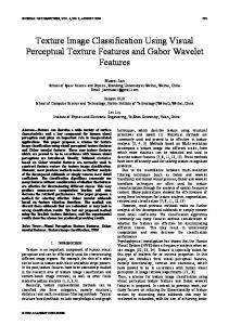
Figure 2.1: Meso- and micro-structures of a woollen fabric.
2.2.1 Micro-geometry The Micro-geometry of a textile is one of the major factors influencing its reflection properties. At a close view the fine scale geometry of a textile becomes visible. At such a close range the loops and weaves of the cloth are similar to hills and valleys, caused by the interlocking of loops; even small holes can be recognized. It is also possible to determine the structure of the yarn, or even point out small fibers. As Lalonde and Fournier (1997) stated, reflection effects of a surface cannot be captured by a single technique, but should in fact be represented at different scales using a hierarchy consisting of three levels: the microscopic level, the mesoscopic level and the macroscopic level (see Figure 2.1). While the microscopic level encompasses all the very fine surface irregularities, e.g. colored pigments and very small bumps, the mesoscopic level, consists of all larger, visible surface irregularities which can be resolved and lead to spatial variation. Finally, the macroscopic level represents large surface structures captured by the geometry of object. The microgeometry of an object is important for the design of reflection models for textiles, because its shape determines the interaction of light with the textile surface. The radiance at a point depends on the points surface normal, as well as on visibility information. Both the normal and the visibility of a surface are purely geometric terms which can be calculated from detailed knowledge about the micro-geometry. In the next section some complex reflection effects will be described which are typically exhibited by textiles and therefore need to be accounted for.
7
Chapter 2 Reflectance Models of Textiles
Figure 2.2: Shadowing and masking effects.
2.2.2 Shadowing and Masking A point lies in shadow if an object occludes the light source from it. In other words, a ray cast from the point in the direction of the light source will intersect the blocker before it intersects the light source. Similarly, masking occurs if the ray cast from a point in the direction of the viewer or camera intersects a blocker first. Seen from the cameras point of view, the blocker is occluding the point. Both effects, shadowing and masking, play a very important role in textiles. There are two cases of shadowing. The first one is global shadowing effects. Global shadowing effects occur if any general object casts shadows onto a textile, for instance a tree casts shadows onto the sweater of the person in its shadow or if parts of the macrogeometry of the garment shadow other parts, for instance a sleeve casts a shadow onto the front of a sweater. These shadows can be detected and handled just by considering the garment’s geometry and the relative locations of objects and light sources. Algorithms like shadow mapping can be used to compute these shadows. The second effect can be called local shadowing, which are due to the height differences of the micro-geometry of the textile. Local shadowing effects can occur when surface irregularities cast shadows onto other parts of the micro-geometry (see Figure 2.2). Obviously, these effects cannot be detected by a general shadowing algorithm without any information about the textiles micro-geometry. Analogously, some parts of the micro-geometry can be occluded by other parts from the viewpoint (Figure 2.2 on the right). Occlusion of micro-geometry can have dramatic effects in certain regular weaves where two colors of yarn are used side by side. At more gazing angles the yarn lying in
8
Chapter 2 Reflectance Models of Textiles
Figure 2.3: Subsurface Scattering. front will nearly completely obscure the yarn next to it, which leads to color shifts.
2.2.3 Subsurface Scattering Some types of materials are not totally opaque at the surface, so light is not only reflected by the surface. Instead, some light also penetrates the surface and is reflected a number of times at irregular angles inside the material, taking on the color of the insides and emerging back out to blend with the surface reflection (Figure 2.3). This property causes the substrate of the material to become visible. Furthermore, a characteristic of subsurface scattering is that the angle of light which strikes the surface will not be equal to the angle of reflection.
2.3 Reflectance Models The following descriptions of the reflectance quantities mostly follow the convention of Nicodemus et al. (1977). Similar descriptions can be found in Suykens et al. (2003), Pharr et al. (2016) and Pont and Koenderink (2005).
9
Chapter 2 Reflectance Models of Textiles
Figure 2.4: Geometry of surface reflection.
2.3.1 Bidirectional Scattering Surface Reflectance Distribution Functions Generally, when light interacts with matter, a photon strikes the surface and a photon is leaving the surface. Each photon can be described by six parameters: the radiation flux incident on a surface from the direction (θi , φi ), within the element of solid angle dwi [sr]. The portion of the incident flux which hits an element of area dAi [m2 ] centered at the point (xi , yi ) will be denoted by dφi [w]. The incident flux is then reflected and scattered before leaving the surface. Due to multiple (subsurface) scattering, the reflected radiance may leave the surface at any location. The radiation flux leaves the surface in the direction (θo , φo ) and at a certain location (xo , yo ). Let the time of interaction at position (x,y) be t and the specific wavelength considered λ . To describe the general case a twelve-dimensional function is needed (Figure 2.4). (xi , yi , θi , φi ,ti , λi ) → (xo , yo , θo , φo ,to , λo )
(2.6)
To simplify this function the dependency on time can be ignored, by assuming that the photon is reflected instantaneously. A second simplification can be done by assuming that the interaction of light with the material does not affect the wavelength of the photon. Consequently the reflectance function is reduced to eight-dimensional. The reflected radiance, which comes from dφi , will be called dLo and is directly proportional to dφi which equals Li ·Cosθi dωi · dA (Equation (2.7)). Although the exact form of light transport is unspecified, dLo and dφi should be linearly related due to the linear nature of reflections:
10
Chapter 2 Reflectance Models of Textiles
Figure 2.5: The parameters of general light-material interaction.
dLo = S · dφi = S · Li · cosθi dωi · dA.
(2.7)
The factor S depends on the location as well as the directions of the incoming and outgoing rays, and is therefore an eight-dimensional quantity. The quantity S is called the bidirectional scattering-surface reflectance distribution function (BSSRDF): SBSSRDF8 = S(θi , φi , xi , yi , θo , φo , xo , yo ).
(2.8)
The BSSRDF describes the relationship between incoming irradiance and outgoing radiance on a general surface and its unit is per steradian per meter squared [1/m2 sr]. Given S and a complete description of incoming radiance from all directions, the outgoing radiance at every point of the surface can be completed. The BSSRDF is a very general property of a surface and captures shadowing, masking and subsurface scattering. But, its high dimensionality makes it very difficult to measure and use.
2.3.2 Bidirectional Reflectance Distribution Function Assuming that the material is uniform, the BSSRDF S and the differential outgoing radiance dLo will both be independent of the position (xo , yo ). Without loss of generality, the point of outgoing radiance (xo , yo ) can be equal to (xi , yi ). See Figure 2.5. We assume here that the entire surface is irradiated by radiance Li (θi , φi ), from direction (θi , φi ) over the solid angle element dwi :
11
Chapter 2 Reflectance Models of Textiles
Lo (θi , φi , θo , φo ) =
�
Ai
S(θi , φi , xi , yi , θo , φo ) · Li · cosθi dωi · dAi
= Li · cosθi dωi
�
(2.9)
S(θi , φi , xi , yi , θo , φo )dAi .
Ai
Nicodemus et al. (1977) define the bidirectional reflectance distribution function (BRDF) as: ρ1 (θi , φi , θo , φo ) =
� Ai
S(θi , φi , xi , yi , θo , φo )dAi
(2.10)
In this formula, the BRDF sums up all scattering contribution over the entire area. Substituting into Equation (2.7) we obtain: ρ1 (θi , φi , θo , φo ) =
dLo (θi , φi , θo , φo ) Li · cosθi dωi
(2.11)
Intuitively, the BRDF relates the outgoing radiance at a particular location to the incoming irradiance on a nearby flat surface patch. Given the incoming irradiance over the full hemisphere, the BRDF fully specifies the outgoing radiance in all directions. Since the intensity of scattered rays falls off very quickly for many materials, one way to simplify the BSSRDF is to completely ignore contributions from the neighborhood. In this case, the BRDF can be seen as a part of the BSSRDF: ρ2 (θi , φi , θo , φo ) = S(θi , φi , θo , φo )
(2.12)
Bidirectional reflectance distribution functions can be classified into two classes, namely anisotropic BRDFs and isotropic BRDFs. Anisotropic BRDF Schlick (1993) introduced the term Anisotropic BRDF with the following words. ”A surface is called anisotropic when the BRDF is a function of the orientation of the surface along its normal (i.e. the BRDF depends on angle φ )”. An anisotropic BRDF does not remain constant when the incoming and outgoing angles are rotated. In this case, a full four-dimensional function is necessary to characterize the behavior of the surface. Anisotropic materials are frequently encountered when the surface has a strongly directional structure at small scale: brushed metals are one example of such materials.
12
Chapter 2 Reflectance Models of Textiles Even textiles with a spatially invariant BRDF will often have an anisotropic BRDF, which is due to the microgeometry of woven or knitted clothing. A very good example for this behavior is the satin weave. The structure of this weave is dominated by long flowing weft threads. Clearly, these threads lie in a preferred direction, resulting in a nonuniform distribution of the normal directions over the azimuth angles, and consequently in an anisotropic BRDF. Isotropic BRDF As defined by Schlick (1993): ”when the BRDF at a point p does not change while the surface is rotated around its normal vector at p (i.e. the BRDF does not depend on angle φ ), the surface is called isotropic”. Some, but not all, BRDFs have this property, they are unchanged if the incoming and outgoing vectors are rotated by the same amount around the surface normal, which is in contrast to anisotropic BRDF. In this case, there is a useful simplification that may be made: the BRDF is really a 3-dimensional function and depends only on the difference between the azimuthally angles of incidence and exitance. ρ2 (θi , φi , θo , φo ) = S(θi , θo , φo − φo )
(2.13)
2.3.3 Bidirectional Texture Function Dana et al. (1996, 1999) introduced the term bidirectional texture function (BTF) to represent spatially-varying reflectance. With the BTF non-local subsurface scattering effects are ignored or pre-integrated Lehtinen (2007). It encodes all other effects such as shadowing, masking and multiple scattering. The BTF is a 6D quantity R(θi , φi ,θo , φo , x , y). Again it can be defined as the BSSRDF integrated over the incident locations or simply a slice of the BSSRDF: R1 (θi , φi , θo , φo , x, y) =
� Ai
S(θi , φi , xi , yi , θo , φo , x, y)dAi
(2.14)
R2 (θi , φi , θo , φo , x, y) = S(θi , φi , xi = x, yi = y, θo , φo , xi = x, yi = y) Figure 2.6 shows the taxonomy of object appearance descriptions with different levels of abstraction. Methods exist for interactive editing of measured BTF Kautz et al. (2007), which enable us to change materials properties by several physically nonplausible operators.
13
Chapter 2 Reflectance Models of Textiles
Figure 2.6: Taxonomy of appearance measurement (Rusinkiewicz and MARSCHNER (2000)).
14
Chapter 2 Reflectance Models of Textiles
2.4 Representation of Spatial Variation using 2D Structures Often the reflection properties of a surface cannot be modeled by a single, homogeneous BRDF, because the reflection of the surface varies locally. In this section, methods will be introduced which are able to capture spatial variation of the reflectance function. These variations can be caused on the one hand by micro-geometry of the surface and on the other hand by color variations. The most simple example is standard texture mapping, where different surface locations map to different colours. Bump mapping (Blinn (1978)) simulates the effect of surface roughness by perturbing the surface normal. Horizon mapping ( Max (1988) and Sloan and Cohen (2000)) enhances bump mapping by handling self shadowing effects. Heidrich et al. (2000) further improve micro-geometry rendering by efficient interreflection estimation using precomputed visibility. Displacement mapping Cook (1984) is typically not considered a reflectance technique since it changes the underlying geometry. However, recent extensions (Wang et al. (2003a, 2016)) to displacement maps are applied at shading time. Occlusion and shadowing are precomputed to allow for interactive rendering. While the above techniques offer different trade offs between computation cost and quality, they all depend on accurate descriptions of the micro-geometry which usually are unavailable and often difficult to acquire from real materials in most cases. As a result, these techniques are often only applied to render synthetic materials.
2.4.1 View-Dependent Texture Mapping While panoramas and mosaics are more tailored to allow free movement within an environment, the following techniques concentrate more on the inspection of an object from different viewpoints. Debevec et al. (1996) model architectural scenes from airborne photo-graphs. The appearance of a surface is captured for a number of directions, storing a texture and its corresponding direction for each view. During rendering, the views associated with the textures are compared to the current viewing direction, and the three textures with the nearest views are selected. The appearance of the surface is reconstructed by blending these three textures. The authors used photographs of buildings to add surface detail onto fairly simple geometrical models and to capture their viewdependent appearance. Different metrics have been proposed to blend the pictures of multiple view-points (Pulli et al. (1997) and Debevec et al. (1998)) to obtain the final image. Recently Matusik et al. (2002) introduced a technique called image-based visual hulls. In their approach a dynamic 3D model is captured using eight video cameras. Based on silhouette information they infer 3D geometry to which view dependent texturing is applied. This method is well suited for structured surfaces with a planar base geometry, as the reconstruction of the relative viewing direction is easy for the planar case. For non-planar geometry,
15
Chapter 2 Reflectance Models of Textiles however, both the acquisition process, as well as the rendering process would become more complex. View-dependent textures do not represent the dependency of the surface appearance on the light direction.
2.4.2 Bidirectional Texture Functions A very similar data structure, which additionally accounts for the light direction is Bidirectional Texture Functions (BTFs). The Bidirectional Texture Functions was first introduced by Dana et al. (1997) and has gained popularity recently. It describes the relationship between incoming and outgoing radiance, without prescribing the means of light transport inbetween. As a result, it is directly measurable and can be applied directly to synthetic scenes. For a number of different sample surfaces, the authors acquired images for varying combinations of light and viewing directions and published the results in the Columbia-Utrecht Reflectance And Texture Database (1999) (CUReT). BTFs are a very effective data structure to represent reflectance data. They are especially well suited to capture the appearance of real-world surfaces. However, the process of acquiring a BTF for a real surface is extremely tedious. Firstly, the data needs to be captured for a sufficiently large number of light and viewing directions, which often requires several hours per surface sample. After that, the image data usually needs to be edited before it can be used for rendering, because the images contain area foreshortened skewed versions of the texture, which most rendering algorithms cannot handle. Liu et al. (2001) tackle the first problem by introducing a method which uses a sparse BTF data set to synthesize images for missing light and viewing directions. Because of the large size of BTF data even at a low sampling, there has been a great deal of previous work on compression methods. The methods can be roughly divided into two groups. While the first group treats the BTF as a spatially-varying BRDF, the second group considers BTF as a general six-dimensional function and applies linear basis decomposition for compression. McAllister et al. (2002) fit Lafortune et al. (1997) to each Texel separately. The compressed data is very compact but the method is limited as a BRDF model is not suitable for the complex shadowing and masking effects typical in a BTF. To better handle the mesostructure, Daubert et al. (2001) add an extra multiplicative view-dependent term to the Lafortune lobes. Meseth et al. (2004) further improve the compression quality at the expense of space by fitting separate Lafortune lobes to the BTF per pixel per view. The other group of methods compresses BTF by basis decomposition or factorization. Matusik et al. (2002) compress six-dimensional reflectance fields by applying principal component analysis (PCA) on image blocks. Kautz and McCool (1999) factorize BTF into product of 2D textures. Koudelka et al. (2003a) apply principal component analysis (PCA) to the full six-dimensional matrix. Vasilescu and Terzopoulos (2004) arranged the BTF into a 3-mode tensor and applied 3-mode SVD (singular value decomposition). This allows for a more flexible compression by reducing view and light dimensions in-
16
Chapter 2 Reflectance Models of Textiles dependently. Compared to PCA this method leads to a higher root-mean-squared error, but the authors claim that their method provides perceptually more satisfactory results. BTFs are straightforward to be incorporated into both offline and online rendering systems. For offline systems, the BTF represented as a collection of textures can be used directly provided there is enough memory to hold the textures. All the compression techniques mentioned previously can be used for interactive rendering. The reduced data, either in the form of parameters for spatially-varying BRDFs, or coefficients of linear bases, are stored in the texture units of the graphics hardware. BTF shading can then be implemented in the programmable pixel shader. Both view-dependent texturing and BTFs capture a surface’s view-dependent appearance by projecting the micro-geometry along the viewing direction onto a twodimensional texture. This approach is well suited for capturing small and fairly flat surface structures. At the silhouettes, however, artifacts will be clearly visible, especially for larger surface irregularities, because both methods are incapable of reproducing the height of the surface irregularities. One of the major aims of this thesis is to build a new BTF measurement device which allows acquiring images of a material from all possible angles of illumination and of camera perspective. The acquired data can be applied directly to synthetic scenes. In Chapter 5 we will introduce in detail all implementation steps from designing the device until saving results in a tabulated BTFs database.
17
Chapter 3 Perceptual Quality Metrics As visual data are intended to be observed by humans, a knowledge of different aspects of the anatomy and psychophysical features of the Human Visual System (HVS) can be used to improve the performance of various computer graphics algorithms. This chapter reviews the anatomy and relevant aspects of the human visual system that bear a significant influence on visual perception, such as glare due to the eye optics, luminance adaptation, contrast sensitivity and visual masking. It finally offers an overview of the general philosophy of two popular and widely used metrics for image quality assessment. Considering that all models in this thesis are luminance based, the aspects of human vision related to color perception are excluded in this section. This part of the thesis is largely based on vision science books authored by Palmer (1999) and Wandell (1995), which are recommended for a more complete and detailed description of the foregoing issues.
3.1 The Human Visual System Vision is a complex process that involve the interaction of numerous components of the human eye and brain. Figure 3.1 illustrates the main components of the human eye, namely; the iris, the lens, the pupil, the cornea, the retina and the optic nerves. In the first stage the reflected rays of light pass through the eye and reach the retina. The retina contains the neuron component of the eye. When light reaches the back of the eye, it enters the cellular layer of the retina. The cells of the retina that detect and respond to light are known as photoreceptors and are located at the back of the retina. There are two types of photoreceptors; rods and cones. Rods are extremely sensitive to light and dominate the low luminance scotopic vision, whereas cones are responsible for color vision at high (photopic) levels. It explains why we are able to have a high visual acuity and color perception under indoor lighting or sunlight, albeit during the night we are highly sensitive to luminance difference. Both rods and cones are responsible for vision at the mesopic range (see Figure 3.2). Rods provide peripheral vision and are achromatic, but cones are tuned to see colors under normal lighting condition. The fovea is the area of the retina with density packed cones that provide the highest acuity vision that is at the center of human gaze. As the
18
Chapter 3 Perceptual Quality Metrics
Figure 3.1: Anatomy of the eye. distance from the fovea increases, the density of cones drops sharply, and the number of rods increases. Light activates the photoreceptors, which modulate the activity of bipolar cells. Bipolar cells interconnect with ganglion cells located at the back of retina. Axons of ganglion cells from the optic nerve carry information to the brain. Two types of neurons, horizontal cells and amacrine cells, are primarily responsible for reaction within retina. The bipolar cells and ganglion cells are organized in such a way that each cell responds to the small circular patch of photoreceptors, which defines the cells’ respective field. The respective field of ganglion cells consists of a roughly circular central area and a surrounding ring. Ganglion cells have two types of receptive fields: on-center-off-surround and off-center-on surround. The center and its surroundings are always antagonistic and intend to cancel one another’s activity. When no light falls on the receptive field, a spontaneus level of activity is recorded from ganglion cells. But when the light enters the surrounding region of the on-center ganglion cells, the level of activity recording in the cell decreases. Conversely a spot of light in the center of the receptive field increases the response rate. A maximum response of an on-center ganglion cell is achieved when the entire center of the receptive field is illuminated. Likewise if only the surroundings is illuminated by a ring of light, then the ganglion cell is maximally inhibited. It is worth to note that if both regions are illuminated, then the response is just above the base-line. This occurs as the effects on center are stronger then those on the surroundings. The off-center on-surround behaves conversely, as illustrated in Figure 3.4. As observed, the uniform illumination of the visual field is less effective as activating a ganglion cell. This configuration makes the ganglion cells sensitive to different levels of
19
Chapter 3 Perceptual Quality Metrics
Figure 3.2: The range of luminance in the natural environment and associated visual parameters. From Ferwerda et al. (1996). illumination crossing the receptive field or what is called contrast. The photo preceptor cells are connected to ganglion cells, whose task is to transmit signals through the optic nerve to lateral geniculate nucleus (LGN) before they are relayed to the visual cortex. The human cortex is divided into six layers. The connection between these layers is shown in Figure 3.3. Primary visual cortex or the V1 layer is directly connected with LGN, and as observed, this layer is responsible for the most complex visual processing and a large number of neurons in V1 are highly specialized for processing information about static and moving objects and are adapted to visual stimuli with specific spatial location, frequency, and orientation. V2 has many properties in common with V1: Cells are tuned to simple properties such as orientation, spatial frequency, and color. The responses of many V2 neurons are also modulated by more complex properties, such as the orientation of illusory contours, binocular disparity (Von Der Heyclt et al. (1984); von der Heydt et al. (2000)) and whether the stimulus is part of the figure or the background. These areas then project to distinct higher-level areas of cortex: orientation to V3, color to V4, motion to V5/MT, and depth to V6.
3.2 Psychophysical HVS Features Despite the similarities between eyes and cameras in terms of optical phenomena, the first and the foremost difference between an eye and a camera is in terms of perception. Visual perception concerns the acquisition of knowledge, that is, vision is a fundamentally cognitive activity ( Palmer (1999)), distinct from purely optical processes such as photographic ones.
20
Chapter 3 Perceptual Quality Metrics
Figure 3.3: The range of luminance in the natural environment and associated visual parameters. From Ferwerda et al. (1996).
3.2.1 Luminance Adaptation The human visual system is much more sensitive to relative differences in luminance than the absolute luminance level. Our sensation is determined by the percentage of difference in the luminance of a surface relative to its background. The luminance of the background signal can mask the visibility of the difference signal. Light adaptation allows the HVS to encode the contrast of the visual stimulus instead of the absolute light intensity. The image contrast is the ratio of the local intensity and the average image intensity. The minimum contrast necessary for an observer to detect a change in intensity is called a threshold contrast and is defined as ΔL , LB ΔL = LO − LB , K=
(3.1)
where LO is the luminace of object and LB is the luminance of background and K is also referred to in the psychophysical literature as the Weber fraction. Weber’s law holds true over a wide range of background luminance and is not valid only at very low or high light conditions.
21
Chapter 3 Perceptual Quality Metrics
Figure 3.4: Retinal ganglion cell responses and contrast sensitivity function
3.2.2 Contrast Sensitivity Figure 3.4 illustrates the neuronal response to cosinusoidal stimuli with various spatial frequencies. In the first case (a), the spatial frequency is low, and the light falling on the entire receptive field is almost constant. As a result, the neuron’s response will be low. In the second case (b), the spatial frequency is high, and as a result, both positive and negative parts of the cosinusoidal stimulus fall onto both the excitatory and inhibitory regions, effectively cancelling each other out. The third case (c) shows that the highest response is generated when the size of the grating matches a single region of the receptive field. The overall change in sensitivity with respect to spatial frequency is plotted in
22
Chapter 3 Perceptual Quality Metrics Figure 3.4-left, and is known as the contrast sensitivity function (CSF). The CSF describes how sensitive an observer is to sine wave gratings as a function of their spatial frequency. Michelson contrast is defined as C=
Lmax − Lmean , Lmean
(3.2)
where Lmax and Lmean refer to the maximum and mean luminance. The HVS is most sensitive to an intermediate range of spatial frequencies (around 46 cycles/degree), and is less sensitive to spatial frequencies both lower and higher than this. For foveal vision, the spatial CSF is typically modeled as a space invariant bandpass function.
3.2.3 Visual Masking Masking and Facilitation are other important aspects in modeling the HVS, which model the interactions between different image components present at the same spatial location. It has been observed in psychophysical experiments, that the presence of one image component (known as mask) decreases or increases the visibility of another image component (known as signal). The presence of the mask generally reduces the visibility of the test signal. However, the opposite is also possible: the presence of a mask may sometimes facilitate detection as well making as it easier to be seen. Usually, the masking effect is strongest when the mask and the test signal have similar frequency content, orientations and color (Winkler (2005)). Usually most of image quality metrics integrate one model of masking or the other, while some incorporate facilitation as well (Lubin (1995)).
3.2.4 Visual Attention The most important function of selective visual attention is directing gaze rapidly towards objects of interest in the visual environment. This ability to orientate rapidly towards salient objects in a cluttered visual scene is of evolutionary significance as it allows the organism to quickly detect possible preys, mates or predators in the visual world. The most important function of Visual Attention (VA) is to direct our gaze to the objects of interest in the visual scene, which is facilitated using rapid, saccadic eye movements. The attentional shift is guided by two main cues, namely, bottom-up and top-down. The former is fast, saliency driven, and independent for a particular task. It is understood that the bottom-up VA is performed in a pre-attentive manner across the visual field (Itti and Koch (2001)). It is thus driven ’automatically’ by certain low-level features that are experienced as visually salient. Top-down attention, on the other hand, is highly dependent on the viewing task and as such, it is typically slower and requires a voluntary effort to shift the gaze. Top-down attention is considered to have a modulatory effect on bottom-up attention (Treue (2003)) and as such, the two mechanisms
23
Chapter 3 Perceptual Quality Metrics together reach a point where the most relevant information is continuously favoured at the expense of less relevant information. Visual attention is guided by a large number of different low-level and high-level attributes (Wolfe and Horowitz (2004)). Low-level attributes include, amongst others, colour, shape, size, and the motion of objects. High-level attributes are based on semantic information and include, for instance, faces and written text (Cerf et al. (2009)). An earlier work suggests that the pre-attentive, salient features are predominant in guiding attention (Wolfe et al. (1989)): however, more recent work indicates that higher-level objects in fact have a stronger impact on VA (Einh¨auser et al. (2008)). Besides the visual attributes, VA has also been found to be highly dependent on the viewing task (Castelhano et al. (2009)). For instance, if a visual scene is observed without any task given, then the viewing behaviour is different as compared to the case where a particular search goal is followed. In the context of visual quality assessment, such a search may aim at the detection of visible distortions in natural scenes. Top-down attention, which mainly accounts for the task influence (Betz et al. (2010)), has been investigated less in comparison with bottom-up attention, and is thus not understood as well. This is partly due to top-down cues being strongly driven by higher cognitive processes, whereas the saliency of the visual stimulus considerably supports the understanding of bottom-up attention. It is well known that what we look at does not necessarily represent what we set our focus onto (Wolfe and Horowitz (2004)). We can, for instance, gaze at a particular point in a visual field, but consciously attend another point in the periphery. Despite this fact, eye tracking and VA were found to be strongly interlinked (Itti and Koch (2001)) and thus, eye tracking experiments (Findlay and Kapoula (1991)) are widely used to measure overt VA of human observers. Saliency maps (SM) created from eye tracking data are instrumental as a ground truth for the design and validation of VA models.
3.2.5 Foveal Vision Bottom-up approaches to image quality assessment are directly connected with the characteristics of the HVS; while most of them concentrate on Foveal Vision, just a few of them incorporate Peripheral Vision (Lubin (1993), Lubin (1995), Wang and Bovik (2001)). Foveal vision is responsible for high- resolution vision, while peripheral vision is a part of vision that occurs outside the fixation area. During the fixation of a human observer at a point in his environment, the region around the fixation point is resolved with the highest spatial resolution, while the resolution decreases with distancing from the fixation point. On the other hand, the contrast can be assessed only locally for a particular spatial frequency. The difference between the details in images could be observed if they are situated close to each other, but the difficulty increases by distinguishing the brighter details from the darker ones if they are distant in observer’s field of view. This feature can be explained by the structure of the retina, in which the foveal region responsible
24
Chapter 3 Perceptual Quality Metrics for the vision of the details spans only about 1.7 visual degrees, while the parafoveal vision can span over 160 visual degrees, with almost no ability to process high frequency information (Wandell (1995)).
3.3 Objective Image Quality Metrics Due to the fact that human observers are the ultimate users in most image-processing applications, the most reliable way of assessing the quality of an image is through Subjective Quality Metrics. However, subjective evaluations are expensive and time consuming, which makes them impractical in real-world applications. Moreover, subjective experiments are further complicated by many factors including viewing distance, display device, lighting condition, the subjects’ vision ability, and the subjects’ mood. Therefore, it is necessary to design mathematical models that are capable of predicting the quality of an average human observer’s evaluation. To solve the problem properly, Objective Quality Metrics have been introduced. The goal of these metrics is to design mathematical models that are able to predict the quality of an image accurately and automatically. An ideal method should be able to mimic the quality predictions of an average human observer. Objective quality assessment methods can be classified into three categories; The first category is full-reference image quality assessment where the undistorted, perfect quality reference image is available. The second category is reduced-reference image quality assessment where the reference image is not fully available. Instead, some features of the reference image are extracted and employed as side information in order to evaluate the quality of the test image. The third category is no-reference image quality assessment, where the reference image is not avalable. Pixel-Based Metrics such as Root Mean Square (RMS) error or Peak Signal to Noise Ratios (PSNR) fail to assess the perceived degree of realism since they neglect important properties of the human visual system and p� oorly predict the differences between the images. The philosophy used in constructing an objective image quality metrics is one of the major criterion employed for their classification. While traditional perceptual approaches to image quality assessment (bottom-up) are directly connected with the characteristics of the HVS and try to simulate all the relevant components and psychophysical features as basic building blocks, and then combine them together, the ultimate goal of the structural similarity based approaches (Top-down) is to make hypotheses about the overall functionalities of the entire HVS and treat the HVS as a black box, where only its inputoutput relationship is of concern. This section gives a overview of the general philosophy of both metrics and introduces the most popular and widely used metrics in each category.
25
Chapter 3 Perceptual Quality Metrics
Figure 3.5: Block diagram of the general framework for the error sensitivity-based quality assessment system (Wang et al. (2004)).
3.3.1 Pixel-Based Mathematical Metrics The two most popular pixel-base metrics are mean squared error (MSE) and peak signalto-noise ratio (PSNR). Assuming I is as original image and I¯ as distorted image, the MSE is then the mean of the squared differences between the gray-level values of pixels in two pictures: � � 1 ¯ y) 2 I(x, y) − I(x, (3.3) MSE = ∑ ∑ XY x y for pictures of size X ×Y . The √ average difference per pixel is thus yielded by the root mean squared error RMSE = MSE. PSNR in decibels is defined as: PSNR = 10log
m2 , MSE
(3.4)
where m is the maximum value that a pixel can take. Both of the methods are widely used in image processing and coding because of their simplicity. However, neither MSE nor PSNR correlate well with scores rated by human observers.
3.3.2 Error Sensitivity Based Image Quality Measurement General Framework of Perceptual Quality Metrics A great variety of quality assessment algorithms based on HVS modeling have common computational parts (Wang et al. (2003b)) which are displayed in Figure 3.5. Pre-processing may include spatial registration, transformation of color spaces, a point-wise non-linearity, point spread function filtering, and CSF filtering, calibration for display devices, alignment and light adaptation. In some metrics, CSF Filtering may be implemented before channel decomposition using linear filters that approximate the frequency responses of CSF during other metrics.
26
Chapter 3 Perceptual Quality Metrics
Figure 3.6: Cortex transform decomposition. The diagram in the middle represents and image in the Fourier domain divided into six spatial and six orientational bands. The images around show content of particular bands in the spatial domain. Other metrics implement CSF as weighting factors for channels after channel decomposition. In the HVS, one modeling strategy for frequency selective channels is channel decomposition. To distinguish between visual stimulus in different temporal and spatial subbands, channels are employed. In this phase, the differences between the quality metrics are mainly in the selected filters (see Figure 3.6). Some of signal decomposition methods which have been used are the Fourier decomposition (Mannos and Sakrison (1974)), Gabor decomposition (Taylor et al. (1997)), local block-discrete cosine transform (Watson et al. (2001)), separable wavelet transforms (Lai and Kuo (2000)), and polar separable wavelet transforms, such as the cortical transform (Watson (1987)) and the steerable pyramid decomposition (Teo and Heeger (1994)). In every channel, error normalization and masking is commonly implemented. The implementation of masking in the majority of models comes in the form of a gain-control mechanism. In a channel, the gain-control mechanism weights the error signal with a space-varying visibility threshold for that specific channel. The adjustment for the visibility threshold at a certain point is computed based on two parameters: HVS sensitivity for that channel
27
Chapter 3 Perceptual Quality Metrics
Figure 3.7: Visible Differences Predictor Model (VDP) where the masking effects are absent and the signal energy is in the vicinity of that point. Error pooling is the process of combining the error signals in different channels into a single distortion/quality interpretation. The typical implementation uses Minkowski summation (i.e. the Lp-norm) on two sets of channels to compute the model response r r = (∑ ∑ | el,k |β )1/β , l
(3.5)
k
where el,k is the normalized and masked error of k-th coefficient in the l-th channel, and β is a constant typically having a value between 1 and 4 (Minkowski (1953)). Visible Differences Predictor The Visible Differences Predictor (VDP; Daly (1993)) is one of the well-known image distortion metrics, which consists of three main components: calibration of the input images, a human visual system (HVS) model and a method for displaying the visible differences. Figure 4.2 shows a schematic view of VDP. The algorithm receives a pair of images (original and compressed images), and parameters for viewing conditions as input. The first stage is the calibration of the input images, that uses the viewing distance and physical pixel spacing to map the visual frequencies expressed in cycles per degree
28
Chapter 3 Perceptual Quality Metrics (c/deg) to frequencies expressed digitally as a fraction of the Nyquist frequency. In the next stage the Human visual system (HVS) is modeled i.e. the lower-order processing of the visual system, such as the optics, retina, lateral geniculate nucleus, and striate cortex. The human visual system (HVS) model uses processes to limit the visual sensitivity. In the beginning, the original pixel intensities are compressed by the amplitude non-linearity based on the local luminance adaptation. Amplitude non-linearity (Axy ) is responsible for simulating light level adaptation by retina and is defined as b Axy = Lxy /(Lxy + c Lxy ),
(3.6)
where Lxy is the input luminance for each pixel, b is 0.63 and C is 12.6 and is expressed in cd/m2 . In this model the adaptation level for an image pixel is determined by taking just the pixel into account. Afterwards, CSF is processed to model the variations as a function of spatial frequency and so as to take into account the global state of luminance adaptation, orientation, image size and eccentricity from the fovea region. The sensitivity S as a function of ρ radial spatial frequency in c/deg is modeled by the following equation (Daly (1993)) S(ρ, θ , l, i2 , d, e) = P · min[S1 (
ρ , l, i2 ), S1 (ρ, l, i2 )] ra · re · rθ
(3.7)
where ra = 0.856 · d 0.14 re =
1 � 1 + ke �
rθ =
(3.8) k = 0.24
� (1 − ob) (1 − ob) cos(4θ ) + 2 2
ob = 0.78
and θ is the orientation in degrees, l is the light adaptation level in cm/m2 , i2 is the image size in visual degrees, d is lens accommodation due to distance in meter, and e is eccentricity in degrees. The parameters ra , re and rθ model the changes in resolution due to the accommodation level, eccentricity and orientation and P is the absolute peak sensitivity of the CSF. The resulting images are decomposed into the spatial frequency and orientation channels using the cortex transform introduced by Watson (1987). The cortex transform is a multi-resolution pyramid that simulates the spatial-frequency and orientation tuning of simple cells in the primary visual cortex. For every channel and every pixel, the global
29
Chapter 3 Perceptual Quality Metrics contrast and elevation of the detection threshold based on masking is calculated. This detecting threshold is then used to normalize the contrast differences between target and mask images. The normalized differences are input into the psychometric function which estimates the probability of detection of differences for a given channel. This estimated probability value is summed across all channels for every pixel, and visualization of visible differences between the target and mask images is performed. The main advantage of VDP is the prediction of local differences between images, while most of the methods, including that recently developed by (Gaddipatti et al. (1997) and Gibson and Hubbold (1997)) do not have such a functionality and provide only a single scalar value as a measure of difference. While this metric is designed for low dynamic range (LDR) images, Mantiuk et al. (2005) proposed an high dynamic range (HDR) extension of VDP, that can handle the full luminance range visible to the human eye. The modifications improve the prediction of perceivable differences in the full visible range of luminance and under the adaptation conditions corresponding to real scene observation. The proposed metric takes into account the aspects of high contrast vision, such as scattering of light in optics (OTF), nonlinear response to light for the full range of luminance, and local adaptation. DRI-VDP (Aydin et al. (2008)) presents a novel image quality metric that can compare a pair of images with significantly different dynamic ranges. The main contribution of the metrics is a new visible distortion concept based on the visibility of image features and the integrity of image structure. The metric generates a distortion map that shows the loss of visible features, the amplification of invisible features, and reversal of contrast polarity. Visual Discrimination Model Another frequently used image discrimination measuring method is the Sarnoff Visual Discrimination Model (VDM; Lubin (1995)). Figure 3.8 illustrates the overall structure of this model. The Visual Discrimination Model acts in the spatial domain by firstly using an approximation of the point spread function of eye’s optics, according to which the input data are convoluted. Next, the signals are resampled to be able to reproduce the sampling of photoreceptor in the retina. To break down the images into seven different resolutions, VDM uses a Laplacian pyramid (Burt and Adelson (1983)). At this stage each resolution must be one-half of the immediate higher image. Band-limited contrast computations are then performed. Next the selectivity of orientations in four different orientations is applied. To do this through steerable filters of Freeman and Adelson (Freeman and Adelson (1991)), a group of orientation filters were implemented. CSF was modelled through normalization of the output of every frequency-selective channel by the base-sensitivity for that channel. To implement masking, a nonlinear sigmoid is used. This is performed after convolving the errors at each level with disk-shaped kernels. Eventually, JND (Just Noticeable Differences) map or a distance measure is calculated as the Lp-norm of the responses of the
30
Chapter 3 Perceptual Quality Metrics
Figure 3.8: Visual Discrimination Model (VDM) masks. In the visual field of an observer, the eccentricity of images is an important factor. VDM is one of the few models that appropriately takes this into account. For color video, VDM was modified to the Sarnoff JND metric (Lubin (1995)), � � 0 M(V ) dV 1 , (3.9) J= ln2 Vmax Mt (V ) V where Vmax is the maximum spatial frequency displayed, M(V ) is the modulation transfer function of the display and Mt (V ) is the threshold modulation transfer function of the human visual system.
3.3.3 Structural Distortion Based Image Quality Measurement The fundamental principle of the structural approach is that the human visual system is highly adapted to extract structural information (the structure of objects) from the visual scene, and therefore a measurement of structural similarity (or distortion) should provide a good approximation of perceptual image quality. Differently from the foregoing metrics, structural similarity based approaches account for a more implicit perception with the assumption that the HVS is adapted for extracting structural information (relative spatial covariance) from images. While the error-
31
Chapter 3 Perceptual Quality Metrics
Figure 3.9: Diagram of the structural similarity (SSIM) measurement system Wang et al. (2004). sensitivity paradigm is a bottom-up approach, simulating the function of relevant earlystage components in the HVS, structural similarity based image quality metrics are topdown approaches, mimicking the hypothesized functionality of the overall HVS. In this section, we will mainly focus on two very recent general-purpose image quality assessment approaches, Spatial Domain Structural Similarity Index (SSIM; Wang et al. (2004)) and Complex Wavelet Domain Structural Similarity Index (CWSSIM; Wang and Simoncelli (2005)). These approaches are based on high-level top-down hypotheses regarding the overall functionality of HVS (see Wang and Bovik (2006)). Spatial Domain Structural Similarity Index Under the assumption that human visual perception is not built for detecting absolute, exact intensities, instead it is adapted to help us navigate the three-dimensional space we live in and, consequently, is highly adapted for extracting structural information from a scene, Wang et al. (2004) introduced the Structural SIMilarity Index (SSIM). The SSIM index is a framework for quality assessment based on the degradation of structural information and is mostly sensitive to distortions that break down natural spatial correlation of an image such as blur, blocking, ringing, and noise. The diagram of this metric is shown in Figure 3.9. The SSIM separates the task of measurement into three functions: Luminance l(x, y), contrast c(x, y), and structure s(x, y). Given two images (or image patches) of x and y for comparison, the comparison functions are evaluated as follow:
32
Chapter 3 Perceptual Quality Metrics
l(x, y) =
2μx μy +C1 , μx2 μy2 +C1
c(x, y) =
2σx σy +C2 , σx2 σy2 +C2
s(x, y) =
σxy +C3 , σx σy +C3
(3.10)
where μx , σx and σxy are defined as follows: N
μx = 1/N ∑ xi i=1
N
σx = (1/(N − 1) ∑ (xi − μx )2 )1/2
(3.11)
i=1 N
σxy = 1/(N − 1) ∑ (xi − μx )(yi − μy ) i=1
Finally, the three similarity functions are combined to yield the general form of the SSIM index structural similarity: SSIM(x, y) = l(x.y)α · c(x.y)β · s(x.y)γ ,
(3.12)
where α,β ,γ are positive constants used to weight each comparison function. The SSIM method purposed by Wang et al. (2004) is a window-based algorithm that uses a square window, moving pixel-by-pixel over the image to measure loss of correlation, luminance distortion and contrast distortion locally. To evaluate the overall image quality, a mean SSIM (MSSIM) index is calculated as follow: MSSIM(X,Y ) =
1 M ∑ SSIM(xi, yi), M i=1
(3.13)
where M is the number of samples in the quality map , xi and yi are the image contents at the i-th local window, and X , Y are the input images. The structural similarity metric yields a result in a range of 0.0 to 1.0, where zero
33
Chapter 3 Perceptual Quality Metrics corresponds to a loss of all structural similarities and one corresponds to being an exact copy of the original image. Images with lighting-related distortions alone yield a high SSIM value while other distortions result in low similarities, corresponding well with the intuitive perception of quality. Complex Wavelet Domain Structural Similarity Index Wang and Simoncelli (2005) proposed a new image similarity measure that was inspired by the SSIM index algorithm. A major drawback of the spatial domain SSIM algorithm is that it is highly sensitive to translation, scaling and rotation of images while perceptual metrics can successfully account for contrast and luminance masking, they are quite sensitive to spatial shifts, intensity shifts, contrast changes, and scale changes. Wang and Simoncelli (2005) suggested to implement a structural similarity metric in the complex wavelet domain and make it insensitive to these ”non-structured” image distortions that are typically caused by the movement of image acquisition devices, rather than the changes in the structure of objects in the visual scene. In addition, if an application requires an image quality metric that is unresponsive to spatial translation, this extension of SSIM can be adopted. Given complex wavelet coefficients cx and cy that correspond to compared image patches x and y, the complex wavelet structural similarity (CWSSIM) is yielded by:
CW SSIM(cx , cy ) =
∗ 2 | ∑N i=1 cx,i , cy,i | +K 2 2 ∑N i=1 | cx,i | + | cy,i | +K
,
(3.14)
where c∗ denotes the complex conjugate of c and K is a small positive constant. The proposed method shows some interesting connections with several computational models that have been successfully used to account for a variety of biological vision behaviors such as those pointed out by Solomon and Pelli (1994); Pollen and Ronner (1981); Ohzawa et al. (1990); Adelson and Bergen (1985); Schwartz and Simoncelli (2001). However, the algorithm does not provide any information of any correspondence between the pixels of the two compared images (a disadvantage compared to registrationbased approaches) and the method works only when the level of translation, scaling, and rotation is small (compared to the wavelet filter size). Brooks et al. (2008) introduced WCWSSIM, a form of CWSSIM that uses weighted results from multiple subbands, where the weights are derived from the HVS contrast sensitivity function. The modification can better handle local mean shift distortions.
34
Chapter 3 Perceptual Quality Metrics
3.3.4 Visual Attention Models Predicting the attentional behavior of human observers during viewing a visual scene is the main purpose of visual attention models. A visual attention model attempts to leverage this idea, and to direct our gaze rapidly towards objects of interest in our visual environment where it can obtain most of the information, while paying less “attention” elsewhere. In the HVS, attention is facilitated by a retina that has a high-resolution central fovea and a low-resolution periphery. While visual attention guides this anatomical structure to important parts of the scene to collect more details, visual attention models are mainly focused on the computational mechanisms behind this guidance. Commonly, most of the modes are not able to predict the sequential order of human fixations, but are limited to predicting the objects of interest and their locations (Privitera and Stark (2000); Foulsham and Underwood (2008)). Numerous VA models were encouraged by early works such as feature integration theory by Treisman and Gelade (1980), the neural-based architecture by Koch and Ullman (1987), or guided search by Wolfe et al. (1989). Especially the latter model constituted a theoretical basis for biologically plausible models incorporating characteristics of the HVS, known as contributing to VA, such as multiple-scale processing, contrast sensitivity, and center surround processing. Probably the most widely used bottom-up VA model following this paradigm is the one by Itti and Koch (2001), which is based on the neuronal architecture of the early visual system, where multiple-scale image features are combined into a topographical saliency map (see Figure 3.10). Itti et al. (1998)’s basic model uses three feature channels for color, intensity, and orientation. This model has served as a basis for later models and a standard benchmark for comparison. This model proves to correlate with human eye movements in freeviewing tasks (Parkhurst et al. (2002); Itti (2005)). An input image is subsampled into a Gaussian pyramid and each pyramid level σ is decomposed into channels for Red (R), Green (G), Blue (B), Yellow (Y ), Intensity (I), and local orientations (Oθ ). From these channels, center-surround ’feature maps’ fl for different features l are constructed and normalized. In each channel, maps are summed across scale and normalized again: fl = N
4 s=c+3
∑ ∑
fl,c,s , ∀l ∈ LI ∪ LC ∪ LO ,
(3.15)
c=2 c+4
LI = {I} , LI = {RG, BY } , LO = {0◦ , 45◦ , 90◦ , 135◦ }
These maps are linearly summed and normalized once more to yield the ”conspicuity
35
Chapter 3 Perceptual Quality Metrics maps”: CI = fI ,CC = N( ∑ fl ),CO = N( l∈LC
∑
fl ),
(3.16)
l∈LO
Finally, conspicuity maps are linearly combined once more to generate the saliency map: 1 S = ( ∑ Ck), 3 k∈{I,C,O}
(3.17)
There are at least four implementations of this model: Itti and Koch (2001), Saliency Toolbox (STB) by Walther and Koch (2006), VOCUS by VOCUS (2005), and a Matlab code by Harel et al. (2007).
36
Chapter 3 Perceptual Quality Metrics
Figure 3.10: Architecture of the model of saliency-based visual attention, adapted from (Itti et al. (1998)).
37
Chapter 4 A Perception-Based Threshold for Bidirectional Texture Functions In this chapter we present and discuss an experimental study on how decreasing the texture resolution influences perceived quality of the rendered images. In a visual comparison task, quality judgments by observers and gaze data were collected and analysed to determine the optimal downsampling of BTF data without significant loss of their perceived visual quality.
4.1 Introduction To exactly simulate the correct reflection behaviour of fabrics, the paths of light within and on the surface of the material should be computed. Given the number of individual components of a thread, such task is computationally not feasible. Bidirectional Texture Functions represent an alternative solution to this problem. But a severe disadvantage of BTFs lies in the size of picture collections needed, as they contain one photograph for each combination of viewing and illumination angles. The disadvantage is particular acute for the purposes of real time rendering, as the entire collection of pictures needs to be kept in the computer memory. Various past projects have therefore focussed on efficient compression methods for BTFs (including reflectance models based on linear factorization and pixelwise bidirectional reflection distribution functions, in short BRDFs, which are the general reflection model from which BTFs are derived, [Filip and Haindl (2009)]. While existing approaches are often technically well motivated, we believe that, before starting to choose how and how strongly to compress BTF data, it makes sense to first take a step back and see how the human observer perceives and judges compressed and non-compressed BTF textures in comparison tasks. Specifically, we look at BTF-based synthetic renderings of three–dimensional objects and ask: when does using high-resolution textures make sense because the high resolution leads to a perceived increase in texture quality? And when can one do just as well with lower resolution textures without perceived loss in quality? In this chapter, we present and discuss an in-
38
Chapter 4 A Perception-Based Threshold for Bidirectional Texture Functions vestigation aimed at locating a robust threshold for downsampling BTF images without loosing perceptual quality. Information about the location of such a threshold is not only of importance to a better understanding of visual perception of textures, especially in object comparison tasks, but also of importance for developing novel data compression methods in synthetic rendering. In the next section, we will review relevant related work. We will then describe our method of experimentation, which involves a quality comparison tasks with pairs of texturized objects of varying BTF quality levels and varying exposure times. Gaze data was collected to aid visual comparison strategy detection. The presentation of study results is then followed by a discussion, conclusions, and an outlook.
4.2 Previous Works Compression methods for BTF data have been studied for many years in order to accelerate rendering and also in order to compress data. However, only rarely the focus was on the perceived quality of the results of compression. Fleming et al. (2003) studied how humans perceive reflections on surfaces, while Lawson et al. (2003) demonstrated the importance of view changes in synthetic picture matching tasks. te Pas and Pont (2005a) showed that differences in the microstructure of a material are hard to distinguish from differences in the illumination, and that light source direction estimation depends on the material’s bidirectional reflection distribution functions or BDRFs (te Pas and Pont (2005b); Khang et al. (2006)). Work by Pellacini et al. (2000) introduced a new light reflection model for image synthesis based on experimental studies of surface gloss perception. Two experiments were conducted to explore the relationships between the physical parameters used to describe the reflectance properties of glossy surfaces and perceptual dimensions of glossy appearance. Psychophysical tests by Mcmillan et al. (2003) showed consistent transitions in perceived properties between interpolate and extrapolate BRDFs in the space of acquisition. Vangorp et al. (2007) found that object shape considerably influences the perception of BRDF samples. Matusik (2003) psychophysically evaluated large sets of BRDF samples, and showed that there are consistent transitions in perceived properties between different samples. The dimensionality surface of materials represented by means of BTF was first analysed by Suen and Healey (2000), where a correlation analysis showed that BTF dimensionality increases almost linearly with elevation angles of illumination and view. However, this study did not investigate any correlation between BTF dimensionality and human perception. The accurate reproduction of material structures that can be achieved by using measured BTFs was investigated in Meseth et al. (2006), while Filip et al. (2008a) performed a psychophysical study to optimize sparse sampling of BTFs data. In a further study, Filip et al. (2009) assessed different uniform reduced samplings of BTF data based on azimuthal angles of view and illumination as well as on elevation angles.
39
Chapter 4 A Perception-Based Threshold for Bidirectional Texture Functions Few of the existing approaches include an investigation of the viewers gaze behavior while viewing the rendered images. A notable exception is the work by Filip et al. (2009) in which location, duration, and frequency of fixations were recorded. Fixation data was used to analyze strategies of the subjects over the course of the experiment (e.g., did locations and durations of fixations change as the study progressed? Both were found to be the case.). Leung and Malik (2001) presented a framework for representing textures combining both reflectance and surface normal variations. The basic idea is to build a universal texton vocabulary that decribes generic local features of texture surfaces. Given the array of textons, the 3D texton model can synthesize an image at any illumination and viewing condition. In short, previous work focussed on the influence of light, viewing, material reflectance, shape, and angular sampling density of BTF data. In this contribution, we investigate the influence on perceived image quality that the size of the individual BTF texture pictures has, based on which a synthetic object’s texture is interpolated. This variable has not been addressed previously. Our aim is to find a threshold for downsampling BTF resolution — that is, for reducing the image size of the individual BTF textures — without any perceived degradation in the quality of the rendered image. Similar to the procedure by Filip et al., we will collect gaze data to aid the detection of visual strategy and its change.
4.3 Method In a pilot study using different self shadowing fabrics, like corduroy and wool, available in the BTF database of the University Bonn1 we established that there are no differences in gaze behavior or perceived quality jugments between fabrics. We therefore decided to here focus on the corduroy dataset, which we will refer to as Cord-256, as its texture pictures are 256x256 pixels. We then generated two new datasets by downscaling the Cord-256 set through bilinear interpolation to respective resolutions of 128x128 pixels (Cord-128) and 64x64 pixels (Cord-64). For each of the three texture data sets, a three-dimensional textured model of a sofa was rendered through the standard BTF rendering method at a screen resolution of 1920x1084 pixels (Figure 4.1). The sofa model was oriented for display to the viewer to present textured parts across a large range of picture depths. We chose a sofa object model for three main reasons: first, to present an everyday object that viewers are familiar with and instantly recognize. Second, to have an object with a structured surface and composition (e.g., individual buttons, cushions, etc.). This is important in order to ensure that a large set of fitting BTF pictures will be selected as basis for the object’s texture, with widely varying illumination and viewing angles. And, 1 http://btf.cs.uni-bonn.de/.
40
Chapter 4 A Perception-Based Threshold for Bidirectional Texture Functions
Figure 4.1: An example of the stimuli used in our study. third, a sofa is a type of object for which a cord texture would be commonly chosen.
4.3.1 Stimulus Pairs Pairs of the rendered images displayed in full screen, native resolution mode were used as experimental stimuli. Each pair consisted of a sequentially presented rendering using two of the three texture resolutions as shown in Table 4.1. A total of 72 image pairs were shown to test subjects. The experiment was performed in three blocks of 24 image pairs each, between which image exposure time was varied. Exposure time per image was either 1000, 2000, or 3000 milliseconds (ms), respectively labeled as short, medium and long test conditions. Presentation order of the three blocks was balanced across subjects based on a Latin square design. Our rationale behind introducing variation of image exposure time was to test for effects it may have on comparative perceived image quality. It seems possible that, for pairs of different images, longer exposures could lead to higher frequencies of detecting that a difference exists. Presentation of images in each pair was separated by 200 ms. After the presentation of the second image in a pair, subjects had 3000 ms to make a decision about the comparative image quality within the pair: was the first or second image of better visual quality? Or were the two images of the same visual quality? Responses were given on a three-key keyboard and were possible at any time after the start of the presentation of the second
41
Chapter 4 A Perception-Based Threshold for Bidirectional Texture Functions
First Image Cord-256 Cord-256 Cord-128 Cord-128 Cord-64 Cord-64
Second Image Cord-64 Cord-128 Cord-256 Cord-64 Cord-256 Cord-128
Table 4.1: Image pairs as experimental stimuli.
1 2 = None
First image has higher quality. Second image has the higher quality. The images have the same quality. Subject is not sure. Table 4.2: Answer posibilities.
image. Subjects were also instructed that they could choose not to press any button if they felt unsure about the comparison. Please see Table 5.2 for an overview. When looking at the six image pairs in Table 4.1, it becomes clear that all pairs are different and that, consequently, any judgment that a pair shows that same image quality will be incorrect. However, subjects were not previously instructed that no same-quality pairs would be shown. After the decision time of 3000 ms had lapsed, the next image pair was automatically presented.
4.3.2 Experimental Setup The images were presented on a 24-inch monitor with a resolution of 1920x1080 pixels at a distance of 70 cm from the viewer. The screen measured 22.35x15.80 inches and subtended approximately 33 degrees of visual angle. Due to the texture pattern, the minimal texture detail (i.e., for the parts of the sofa at the greatest depth in the image) had a cycle of 4 pixels, which means a subtended angle for a viewer of about 6 cycles per minute of a degree of arc. An SMI RED250 remote eye tracking system was used in binocular mode with 250 Hz fixation detection, in order to record subject’s fixation behavior. SMI BeGaze 2.4 software was used for subsequent analysis of gaze data. Subjects. A total number of 20 subjects, 12 males and 8 females, participated in the experiment. Subjects were undergraduate or graduate students or department members
42
Chapter 4 A Perception-Based Threshold for Bidirectional Texture Functions
Cord-256 / Cord-128 Cord-128 / Cord-256 Cord-64 / Cord-256 Cord-256 / Cord-64 Cord-64 / Cord-128 Cord-128 / Cord-64
# correct 24 39 195 193 193 196
# equal (incorrect) 167 156 25 24 25 19
# other (incorrect) 49 45 20 23 22 25
av. fix. dur. [ms] 386.48 398.51 404.14 412.01 418.08 407.59
av. fix. freq. 2.32 2.25 2.21 2.20 2.14 2.20
Table 4.3: Frequencies of correct answers, incorrect equal-quality answers, and other incorrect answers (accumulated over all 20 subjects; sum of answers per pair: 240); average fixation durations and average fixation frequencies per image pair presentation.
in Computer Science or Civil Engineering, and they were not informed about the purpose of the experiment prior to conducting it. The age of the test subjects ranged from 22 to 39 years (mean = 30.5). Subjects had normal or corrected-to-normal visual acuity. Procedure. Test subjects were seated in front of the monitor and the eye tracker, introduced to the setup and to the experimental procedure, including the answer options. Before the start of the experiment, subjects were asked to read and sign a declaration of informed consent. Subjects could abort the experiment at any time and were guaranteed anonymous treatment of all collected data. They were familiarized with the used sofa images through a preliminary test round with eight image pair comparisons, the results of which were discarded for the subsequent analysis. Then, the subjects were calibrated on the eye tracker and the first of the three test blocks was presented. Calibration was repeated before each subsequent block. Each subject needed about 30 minutes to complete all three blocks.
4.4 Results The section consists of two parts: an analysis of subject performance (i.e., the subjects’ ability to judge image quality differences for the six pairs of Table 4.1) and an analysis of gaze data (locations, frequencies, and durations of fixations).
4.4.1 Subject Performance Analysis The first three columns of Table 4.3 illustrate the numbers of correct and incorrect answers given for each of the six image pairs. Incorrect answers are provided as incorrect equal answers and as other incorrect answers. Looking at the numbers suggests that differences exist between the six pair conditions for numbers of correct answers. A Friedman ANOVA confirms the existence of significant differences (χ 2 (2) = 41.989, p < 0.001, r = 0.952). Two groups of pair comparisons exist, irrespective of the presentation
43
Chapter 4 A Perception-Based Threshold for Bidirectional Texture Functions
Cord-256 Cord-128 Cord-64 First Image Second Image First Block Second Block Third Block
AFD[ms] 429.78 436.45 444.90 422.43 493.09 375.08 405.25 448.71
FF 2.24 2.23 2.17 2.38 2.05 2.33 2.30 2.02
Table 4.4: Average Fixation Duration[ms] (AFD) and Fixation Frequency (FF) for different image quality levels, first and second images, and for blocks.
order: as a first group, Cord-256 and Cord-128 with lower performance, as a second group Cord-256 and Cord-64 as well as Cord-128 and Cord-64, with higher performance. The same groups can be formed for the number of incorrect equal answers (χ 2 (2) = 73.935, p < 0.001, r = 0.920). The first group has many more incorrect equal answers than the second. A breakdown of performance and incorrect equal counts for the three exposure duration conditions (short, medium, long) revealed no significant differences. In order to check for training effects, we compared numbers of correct answers for the three blocks (first: 268, second: 274, third: 297). For each block, a total of 480 answers were collected across all 20 participants. A Friedman test revealed significant differences between the blocks (χ 2 (2) = 6.195, p < 0.05, r = 0.952). A comparisons of means shows a positive training effect.
4.4.2 Gaze Fixation Analysis We next analyzed subjects’ gaze fixation distributions across the sofa image in order to assess whether differences exist for different exposure durations and for different image pair comparisons. Fixation counts for cells in an overlaid 16x16 grid are shown in Figure 4.2 (upper part) for nine conditions. Fixation count patterns between any pair of these nine conditions are significantly correlated with all r > 0.850 and p < 0.001. Table 4.4 shows average fixation duration (AFD, in ms) and fixation frequencies (FF). For the three BTF resolution conditions, a Friedman ANOVA shows significant differences in FF (χ 2 (2) = 6.495, p = 0.039, r = 0.697) and AFD (χ 2 (2) = 7.777, p < 0.03, r = 0.649). AFDs decrease and FFs increase from lower to higher resolution textures. For first and second images, a Wilcoxon test shows a significantly lower FF on the second image (Z = 3.062, p < 0.003, r = 0.684) and a longer AFD on the second (Z = 2.420, p = 0.025, r = 0.541). For the first, second, and third blocks we
44
Chapter 4 A Perception-Based Threshold for Bidirectional Texture Functions
Cord-256 Cord- 64 Cord-128 Cord- 64 Cord-256 Cord-128
r 0.808 0.753 0.015
p 0.0001 0.0001 0.0175
Table 4.5: Correlations between VDP results and fixations independently of exposure durations and presentation order.
found an increase in AFDs (χ 2 (2) = 8.527, p = 0.045, r = 0.623) and a decrease in FFs (χ 2 (2) = 8.954, p = 0.011, r = 0.608). In order to check whether the subjects’ fixation location patterns were driven by visually perceivable differences between images in our BTF image pairs, we employed the Visible Difference Predictor (VDP) (Mantiuk et al. (2005)). VDP simulates low level human perception for known viewing conditions (in our case: a resolution of 1920x1080 pixels at an observer’s distance of 0.7m). The last row of Figure 4.2 shows the visually perceivable differences per image pair (irrespective of presentation order) as predicted by VDP. Correlations between VDP results and respective fixation location patterns can be seen in Table 4.5 (as averaged over exposure durations; displayed in the columns above each VDP result in Figure 4.2). The results confirm the two groups of image pairs found in the subject performance analysis: (1) a weak correlation for Cord-256 and Cord-128 pairs and (2) strong correlations for the pairs within the group of Cord-256 and Cord-64 as well as Cord-128 and Cord-64. Lastly, existence of the two groups is further supported by average fixation durations and fixation frequencies for the individual image pairs as seen in the right-hand part of Table 4.3. AFDs in the first group are significantly lower than in the second (χ 2 (2) = 73.935, p < 0.001, r = 0.920), while FFs are significantly higher (χ 2 (2) = 41.989, p < 0.001, r = 0.952).
4.5 Discussion The results show that two groups of image comparisons exist in our study. The first group consists of comparisons between Cord-256 and Cord-128. For this group, subjects are largely unable to perceive existing differences between the images. Instead, they frequently judge the pair to consist of the same image. The higher average FFs and lower AFDs in this group suggest more visual search for existing differences. The VDP model predicts few visually perceivable differences for image pairs in this group. The second group consists of comparisons between Cord-256 and Cord-64 as well as between Cord-128 and Cord-64. For this group, subjects are largely able to see the differences among the pairs. Occurrences of incorrectly labeling pairs as equal are few. The lower FF counts and higher AFDs suggest that subjects are better able to concentrate
45
Chapter 4 A Perception-Based Threshold for Bidirectional Texture Functions
Figure 4.2: Fixation count in different test duration and responses of visual difference predictor for tested image pairs. on informative locations (i.e., on locations at which the images within a pair differ). The VDP model predicts a higher number of differences which are also detectable with higher probability. A comparison between the fixation location patterns between the first and the second group reveals that, irrespective of the group, subjects seem to fixate on similar locations, and do so with similar frequencies. One conclusion is that they employ similar strategies while inspecting image pairs of any of the six types. VDP predictions differ markedly between the groups. We observed strong correlations between locations of predicted visually perceivable differences and observed fixation patterns only for the second group of comparisons. We interpret this as evidence for the subjects’ ability to pick up on differences in the second group and use information about the location of these differences for image comparisons. A significant, albeit very weak, correlation exists for the first group.
46
Chapter 4 A Perception-Based Threshold for Bidirectional Texture Functions When comparing AFDs and FFs between the three BTF image qualities, it seems likely that low image quality leads to less visual search, suggesting that subjects are fast at discerning features that hint at low quality. AFD was lowest for the first block and then increased over the course of the experiment, while the average FF decreased. This pattern is in line with the one presented in (Over et al. (2007)) and suggests that subjects may have applied a coarse-to-fine approach during visual search. Within the first comparisons, subjects may notice locations at which differences between images of different visual quality are located, leading to more fixations at them. This may differ for behavioral patterns in the beginning, when subjects spend more time carefully searching for differences among image pairs, resulting in shorter and a larger number of fixations. Longer AFDs in the second image in a pair compared to the first indicate that by the time subjects look at the second image they already have formed hypotheses about where to look for differences. There were no differences in performance and gaze fixation for different exposure durations. The main purpose of this study was to locate a threshold for robust, effective BTF compression based on a downsampling of BTF pictures. Above the threshold, differences between pictures are not visually perceivable by a human observer. Our results clearly indicate that differences between Cord-256 and Cord-128 lie above such threshold, while differences between Cord-256 and Cord-64 as well as between Cord-128 and Cord-64 lie below it. The results are very likely to apply to all self shadowing fabrics.
4.6 Conclusion The results of our study narrowed the bracket in which the threshold is located that separates visually perceivable differences in BTF renderings from those that are not. Consequently, we can now suggest a perception-based criterion for downscaling BTFs. A result for image synthesis is that, above the threshold, the lowest texture resolution available can be used without visually perceivable degradation of image quality. This allows to significantly reduce computer memory usage in BTF rendering. A logical next step would be to conduct a localized search within this established bracket, that is, between Cord-128 on one side and Cord-64 on the other, since our study showed that observers cannot distinguish between Cord-256 and Cord-128. In the future, we also plan to look for ability- and/or skill-dependent differences in the ability to distinguish BTFs at different quality levels. We have already conducted pilot studies with groups of engineers and artists (see Appendix B). In general, there are few studies on perceptual measures of rendering algorithms. This study is a first step in this direction. Also, this study could open up new research insights for the field of perception of textures of real objects, especially in object comparison tasks. For example, future questions
47
Chapter 4 A Perception-Based Threshold for Bidirectional Texture Functions that can be addressed could relate to the categorization of textures in object perception, either general or with regard to group-dependent or individual differences, to effects of attention in object texture perception, or to effects of expertise which may be acquired through completing series of object texture comparisons similar to the ones employed in this study.
48
Chapter 5 Low Cost Rapid Acquisition of Bidirectional Texture Functions for Fabrics This Chapter will present in detail a new low cost programmable device for the rapid acquisition of BTF datasets. The device allows to acquire BTF databases at a fraction of the cost of available setups, and allows to experiment when a texture resolution and sample density increase in the parameter space is not perceivable by an observer of the renderings. Additionally it will be proved that using smaller resolution textures and decreasing the samples in parameter space does not lead to a loss of picture quality.
5.1 Introduction In practice, BTFs use large collections of digitally acquired pictures of a material taken at discretely varying illumination and viewing angles. When a simulation of the material needs to be computed for rendering, the viewing and illumination vectors are used to pick matching textures from the collection of scanned textures, and, if the angles do not match with angles of the corresponding textures, neighbouring textures are interpolated at the point to be rendered. A big disadvantage of BTFs is that state of the art measurement devices require expensive robotics setups and that the measurement process is very time consuming since direction dependent parameters (light- and view-direction) have to be controlled accurately. Otherwise the resulting data will be poor. Moreover, the size of BTF data can range from hundreds of megabytes to several gigabytes, since in the ideal case a large number of high resolution pictures have to be used. For real time rendering this is a big disadvantage, since either the entire collection of pictures needs to be kept in the computer memory, or computationally expensive methods have to be used to intelligently load/unload the textures. As mentioned in Chapter 4 several authors focused on efficient compression methods for BTF data but The focus was rarely set on the perceived quality of the results of compression or loading/unloading mipped-mapped textures. An impor-
49
Chapter 5 Low Cost Rapid Acquisition of Bidirectional Texture Functions for Fabrics tant step before starting to compress BTF data, is to see how many measured samples at which resolution are needed to have the same perceived quality when rendered instead of using a complete database at the highest possible resolution, or automatically degraded texture downscalings not taking into account the final user. If the texture database is perceptually sound, then it can be reduced in its number of texture samples. In this chapter we present two basic improvements to the use of BTFs for rendering: firstly we want to address the cost of BTF acquisition by introducing a flexible low cost step motor setup for BTF acquisition allowing to generate a high quality BTF database taken at user defined arbitrary angles. Secondly, we want to adapt the number of acquired textures to the perceptual quality of the renderings, so that the database size is not overbloated and can fit better in memory when rendered. In oder to do this, we will use Daly’s Visual Difference Predictor (VDP;Daly (1993); Mantiuk et al. (2011)) to prove that the reduced dataset acquired through our device does not lead to perceivable differences for the rendered images for a viewer. In the next section, we will introduce how we plan to reduce the BTF database. Next the BTF measurement setup will be described in detail. Then an experimental evaluation of the BTF acquisition setup results will be presented, proving that no perceivable differences in the renderings are made by reducing the BTF database angle steps. Finally we will present some conclusions, and an outlook.
5.2 Reducing the Sample Density In Filip et al. (2008a, 2009); Azari et al. (2016) the authors propose to reduce the BTF dataset size by down-sampling resolution and view/illumination angles and proved that perceived quality did not decrease. The outcomes could help prevent capturing redundant images with high resolution from a sample and this will reduce the acquisition time significantly. We propose a preprocessing step before starting to acquire the complete database to determine the down sampling threshold. As this threshold depends on the surface characteristics of a material, each sample should be tested individually. The first step in the proposed preprocessing method is to generate solely samples required to texturing a section of a sphere, as shown in Table 5.1. The produced database therefore covers a fourth of the BTF database (22*22=484 samples) as opposed to a complete BTF database (81*81=6561 samples), which we will refer to as ’BTF’. In the next step this database is down-sampled using reduced densities and resolution according to Filip et al. (2008a, 2009); Azari et al. (2016). Four down-sampling schemes are adopted. In the first scheme we reduced the resolution of the each texture from 265 x 256 to 128 x128: it will be referred in this Chapter to as ’BTF-R’. In order to obtain considerable reduction of BTF dataset size we adopted two different BTF sampling schemes denoted as A, B from Filip et al. (2009). While scheme ’A’ preserves the original sampling of elevation angle θ but reduces the number of azimuthal samples along angle φ , scheme ’B’ reduce sampling for both angles (see Table 5.2).
50
Chapter 5 Low Cost Rapid Acquisition of Bidirectional Texture Functions for Fabrics
Conventional BTF Database
θ θ θ θ θ θ
81 Samples = 0◦ , # φ = 1 = 15◦ , # φ = 6 = 30◦ , # φ = 12 = 45◦ , # φ = 18 = 60◦ , # φ = 20 = 75◦ , # φ = 24
Proposed BTF Database
22 Samples θ = 0◦ , # φ = θ = 15◦ , # φ = θ = 30◦ , # φ = θ = 45◦ , # φ = θ = 60◦ , # φ = θ = 75◦ , # φ =
Rendered BTF Data
1 2 4 4 5 6
Table 5.1: Sampling of the Conventional BTF Database (left) compared with the Proposed BTF Database (center) and the Rendered Full and partial sphere (right).
Scheme A (11 Samples) θ = 0◦ , # φ = 1 θ = 15◦ , # φ = 1 θ = 30◦ , # φ = 2 θ = 45◦ , # φ = 2 θ = 60◦ , # φ = 2 θ = 75◦ , # φ = 3
Scheme B (11 Samples) θ = 0◦ , # φ = 1 θ = 18.75◦ , # φ = 1 θ = 37.5◦ , # φ = 2 θ = 56.25◦ , # φ = 3 θ = 75◦ , # φ = 4
Table 5.2: The down-sampled schemes: A along azimuth θ , B along azimuth θ and elevation φ angles.
51
Chapter 5 Low Cost Rapid Acquisition of Bidirectional Texture Functions for Fabrics Database BTF BTF-R BTF-A BTF-B BTF-C
Number of Samples (22 x 22) (22 x 22) (AxA) (BxB) (22 x B )
Resolution 256 x 256 128 x 128 256 x 256 256 x 256 256 x 256
Table 5.3: The Proposed BTF Database (BTF) compared with the down-sampled BTF Database using reduced resolution (BTF-R) and densities ( BTF-A, BTF-B and BTF-C).
It should be noticed that BTFs require directional sampling of both illumination (θi , φi ) and view directions (θo , φo ) and in these two directions different sampling schemes can be adopted without limiting practical usage of the data. We choose three down-sampled BTF datasets. The first two are straightforward and down-sampled both illumination and viewing directions in the same way, using a combination of the schemes AxA and BxB, which we will refer to as ’BTF-A’ and ’BTF-B’. The third one used scheme B on just view directions (’BTF-C’). Consequently, four down-sampled datasets are generated (see Table 5.3). The samples in each databases are then used to render the sphere in order to check the influence of down-sampling on the perceived quality. This can be done either by using a Subjective Quality Metrics or an Objective Quality Metrics [Wang and Bovik (2006)]. Since human beings are the users in most image-processing applications, the most reliable way of assessing the quality of an image is by using subjective quality metrics. Indeed, the mean opinion score (MOS), a subjective quality measure requiring human observers, has been long regarded as the best method of image quality measurement. However, the MOS method is expensive, and it is usually too slow to be useful in realworld applications. To solve the problem Objective Quality Metrics have been proposed. The goal of these metrics is to design mathematical models that are able to predict the quality of an image accurately and automatically. An ideal method should be able to mimic the quality predictions of an average human observer. One of the most popular and widely used objective quality metric based on models of the human vision system is Daly’s Visual Difference Predictor (VDP; Daly (1993); Mantiuk et al. (2011)). We used VDP to assess visual differences between the rendered spheres by different down-sampling schemes and to find a compression threshold. Based on this threshold a compressed BTF database could be acquired without capturing redundant images which reduce strongly the acquiring time. To test the method introduced above a measurement setup for the acquisition of BTF data has been built, which will be explained in detail in the next section.
52
Chapter 5 Low Cost Rapid Acquisition of Bidirectional Texture Functions for Fabrics
Figure 5.1: The first BTF measurement device. The equipment consists of a personal computer with a 24-bit RGB frame grabber, a robot arm to orient the texture samples, a halogen bulb with a Fresnel lens which produces a parallel beam, a photometer, and a 3-CCD color video camera (not shown), Dana et al. (1997).)
5.3 Acquisition Setup The acquisition of 2D textures is a very simple process which can be performed using a standard 2D scanner or an off-the-shelf digital camera and image-processing software. On the contrary, the acquisition of BTFs requires a complex and controlled measurement environment. Since BTF acquisition can be seen as physical measurement of real-world reflection, special attention has to be paid to device calibration and image registration. Otherwise the measurements will contain inaccuracies which may generate visible rendering artifacts.
5.3.1 Prior Works Dana et al. (1997) built the first BTF measurement device. A robot arm is used in this device to orient the texture sample at arbitrary orientations and the camera and light orbit around the sample. 205 combinations of light and view directions are sampled for each material, and more than 60 materials have been measured and published1 . Due to the sparse sampling, it is not practical to use the measured data for rendering directly. More recently, researchers have built similar setups and provided measurements at higher angular resolutions [Sattler et al. (2003); Koudelka et al. (2003b); Furukawa et al. (2002); Haindl et al. (2012)]. Significantly to the gonioreflectometer for BRDFs, only one sample is measured at a time for each lighting and viewing directions, however, unlike the in gonioreflectometer case where one value is measured per setting, in these newer methods each sample is a texture. 1 http://www1.cs.columbia.edu/CAVE/software/curet/
53
Chapter 5 Low Cost Rapid Acquisition of Bidirectional Texture Functions for Fabrics
Figure 5.2: Gonioreflectometer Sketch of the proposed camera array (151 digital cameras), M¨uller et al. (2005). For a fast high quality acquisition of BTFs M¨uller et al. M¨uller et al. (2005) propose an array of 151 digital still cameras mounted on a hemispherical gantry. The on-camera flashes serve as light source. By synchronizing the cameras, 151*151=22801 images can be captured in 151 time steps and the authors report a measurement time of about 40 minutes. In this setup no moving parts are needed. Hence, the region of interest is known for every camera and consequently, there is no need for a time-consuming detection of the region of interest. While this is a big improvement in terms of measurement time, the setup is large and expensive (see Figure 5.2). Schwartz and Klein (2012) proposed a dome setup employs eleven cameras that are mounted on an arc, providing some degree of parallelism, combined with a turntable for capturing the object from all sides. 198 LED light sources are mounted on the full dome, avoiding the need for mechanical movement for having light directions from all sides. Later K¨ohler et al. (2013) presented OrcaM, a device for simultaneous acquisition, which employs a full-spherical construction, a movable projector-camera unit, 633 individually controllable LEDs and a height-adjustable turntable with a glass carrier. The design allows data acquisition from all possible directions in a single pass without any user interaction. Han and Perlin (2003)and Ihrke et al. (2012) introduced a measurement setup based on a kaleidoscope which allows viewing a sample from multiple angles at the same time through multiple reflections. Illumination is provided by a projector pointing into the kaleidoscope. By selectively illuminating a small group of pixels, the light direction can be controlled. Since there is no moving part in this setup, measurement is very fast. However, the equipment is difficult to build and calibrate. In addition, due to multiple reflections in the optical path, the resulting quality tends to be rather low (see Figure 5.3). Dana and Wang (2004) proposed a setup based on a parabolic mirror. While their setup can provide higher quality measurements than the kaleidoscope setup, they can only
54
Chapter 5 Low Cost Rapid Acquisition of Bidirectional Texture Functions for Fabrics
Figure 5.3: A measurement setup based on a kaleidoscope Han and Perlin , Han and Perlin (2003). capture a single spatial location at a time. As a result, it does not offer any acceleration compared to the gonioreflectometer-like approaches. The standard gonioreflectometer-like approaches allow to capture high–quality BTFs reliably. Their drawback is the speed - several hours are needed and this makes measured BTFs an expensive resource. Using mirrors may be a promising approach in the future, but the quality of the measurements of current systems remains dubious. Using a camera array sensor greatly reduces measurement times at the expense of the costs for a large number of cameras. Ngan and Durand (2006) propose an approach which uses sparse measurements to reconstruct a full six-dimensional Bidirectional Texture Function (BTF). The reconstruction require input images from the top view to be registered, which is easy to achieve with a fixed camera setup. Bidirectional properties are acquired from a sparse set of viewing directions through image statistics and therefore precise registrations for these views are unnecessary. The technique is based on multi-scale histograms of image pyramids and he full BTF is generated by matching the corresponding pyramid histograms to interpolated top-view images. The technique cannot capture high-frequency effects such as highly specular materials and the statistical characterization does not handle the geometric effect of parallax but it reproduces some of its effects such as masking. The statistical reconstruction tends to work best on materials with complex spatial structure (e.g. wool, proposte), as the high-frequency content and the statistical variation dominate the visual appearance(see Figure 5.4).
55
Chapter 5 Low Cost Rapid Acquisition of Bidirectional Texture Functions for Fabrics
Figure 5.4: Ngan and Durand (2006)’acquisition setup - both the camera and the measured target are fixed, and a handheld wireless flash is used as the light source. During measurement, the user moves the flash source around to roughly cover all possible directions, and remotely triggers the camera shutter to take pictures.) In the next section our proposed measurement device will be introduced in detail.
5.3.2 The Proposed Measurement Device During the measurement the light source and the sensor are positioned at various angles covering the entire hemisphere above a flat sample of a homogeneous material. In other words, the system allows acquiring images from all possible angles of illumination and of camera perspective. The proposed device (Figure 5.5) is the result of our attempts to find a setup covering the 4 degree of freedom available in a BTF. We set our reference coordinate as shown in Figure 5.5. The origin is placed on the center of the sample. The sample can rotate about the x, y and z axes. While the light can rotate about z-axis using a step motor, the camera is fixed. The camera and light are directed to the center of the sample. The system has 4 degree of freedom and is appropriate for anisotropic material. To rotate the sample we decided to use a combination of three step motors [1-3], (see Figure 5.5). With these motions three degree of freedom are achieved ( φi , θo , φo ). To reach the additional degree of freedom θi , the light should rotate in the altitude direction. For this reason, we mounted our light source on an axes and rotate it with a wheel which can move with the help of the step motor number 4 (see Figure 5.5). The length of the light radius is adjustable. The system is composed of different parts. The main component is an Arduino Mega 2560 which is equipped with a RAMPS 1.4 board and the Marlin operating system. The
56
Chapter 5 Low Cost Rapid Acquisition of Bidirectional Texture Functions for Fabrics
Figure 5.5: The proposed setup Arduino takes commands from a host PC and controls the motors and the remote control of the camera. This is done by using a serial connection between the Arduino and the host PC. The commands are transmitted as Gcodes2 . Hardware: According to the hardware producer, the relationship between the voltage on the potentiometer and the motor current is given by, A=
Vre f 8 · Rs
(5.1)
where A is the motor current and Vre f is the voltage on the potentiometer: in our case the drivers have a resistance Rs of 0.1Ω. This formula is driver specific: if another driver is used, the values have to be updated or another formula could be necessary. The system uses four step motors to move the sample in all directions. We decided to choose SM42051 and E7126-0140 step motors 3 . The SM42051 has 0.196 Nm torque with max rated current of 0.6 A and is used to rotate the sample around the x and y axes, which we will refer to as S1 and S2. Because of the higher friction force by rotating the light and sample about z axis two E7126-0140 step motors with 1.6 Nm torque has been chosen (S3, S4). The motors are connected to the according S1, S2, S3 and S4 axes of the RAMPS 1.4 board. S1, S2 and S3 move the sample while S4 moves the light source. Each step motor has a 1.8◦ step resolution, Therefore in order to rotate the S1,S2 2 Gcode
is a control language for CNC (or Reprap) machines
3 http://www.emisgmbh.de/schrittmotoren.html
57
Chapter 5 Low Cost Rapid Acquisition of Bidirectional Texture Functions for Fabrics and S3 axis by 9◦ , 5 steps are needed. To achieve adequate leveraging, the S4 axis is equipped with a gear. The gear ratio is 9 : 120. Each tooth of the small gear wheel corresponds to a 3◦ movement of the light, which is the smallest possible movement of Z axis. To move the small gear wheel one tooth further, 22.22 motor steps are necessary. To have a reference, the S1,S2 and S4 axes have end-stops which are triggered whenever the corresponding axis reaches its maximum or minimum rotation (See Appendix A for more detail). Software: The system uses the 3D printer software Marlin as operating system. The Marlin firmware is customized for this purpose. Therefore, the file configuration header is changed at specific points, so that the system is connected to the host PC using a serial connection and receives commands from that PC. As host software for the PC Pronterface is used. After connection to the Arduino, various commands can be send to the Arduino. The camera is the center piece of hardware in our measurement setup. Therefore special attention was paid to choose the camera. We selected a Nikon D750 DSLR camera, a high-end and full format digital camera intended for professional photography. The camera captures the material sample’s appearance at different positions in raw format at a resolution of 6016 x 3375 pixels. A fixed length SIGMA camera lens (105 mm F/2.8) is mounted on the camera. Via an IR Remote Control the camera’s shutter is released. The other important piece of hardware in the measurement setup is the light source therefore it should be selected carefully as well. The decision for a specific light source was based on the emitter geometry and the lamp‘s photometric properties. An OSTARLighting LED Light Source [Osram GmbH]. During the Acquisition some pre- and post- processing steps are necessary to achieve the higher texture quality , see Figure 5.6. in the next sections we will gige an overview of this steps.
5.3.3 Low-level pre-processing Besides a controlled environment and suitable equipment, we applied a number of standard algorithms to further increase the quality of the images that are used as input to our measurements. These algorithms are Geometric and Colorimetric Camera Calibration. Geometric Camera Calibration A geometric calibration has to be applied to the camera to reduce the geometric distortion caused by the optical system of the camera. Most algorithms assume that images are acquired using a perspective projection. This is true for pinhole cameras but not necessary for cameras with a lens system within the limits of physics. Especially for wide angle lenses, a geometric correction needs to be applied to the acquired images. Geometric calibration involves the recovery of the camera’s extrinsic and intrinsic parameters.
58
Chapter 5 Low Cost Rapid Acquisition of Bidirectional Texture Functions for Fabrics
Figure 5.6: BTF acquisition steps. While the intrinsic parameters relate the camera’s coordinate system to the idealized coordinate system, the extrinsic parameters relate the camera’s coordinate system to a fixed world coordinate system and specify its position and orientation in space. The actual transformation of the camera’s lens system is described by its intrinsic parameters. To measure intrinsic and extrinsic parameters several images of an object with a pattern of square grids have been taken. The lens settings are the same as those used to capture the actual images of the object. To extract the feature points from the calibration images an implementation of the Harris detector Harris and Stephens (1988) included in Bouguets camera calibration toolbox Strobl et al. (2006) is used. In standard camera calibration techniques Strobl et al. (2006), the geometry of the calibration object will be used to extract the intrinsic data such as the focal length and radial and tangential distortion coefficients. At the next calibration step the input images will be rectified resembling a perfect perspective projection. Colorimetric Camera Calibration To achieve the best possible color reproduction, the camera has to be color calibrated as well. For a digital camera, the recorded color of an object depends on multiple factors: the spectral response of the object, the color of the light source, the properties of the optical system, the sensor and the image processing steps applied by the camera itself or other software. The goal is to faithfully record the object’s color independently of all these factors. In an ideal case, one would like to accurately measure the continuous spectrum of the visible light. Measurement devices such as a spectrophotometer perform a very dense sampling of the spectrum. In contrast to that, most digital camer-as record only three color values per pixel (tristimulus values) Hunt (1995) obtained by integrating the incident spectrum with the response curve of each CCD sensor. Since different spectral light can result in the same tristimulus values (metamerism) Luther (1927) color
59
Chapter 5 Low Cost Rapid Acquisition of Bidirectional Texture Functions for Fabrics measurements done with a tristimulus device are always an incomplete representation of the actual spectrum. In order to relate the recorded color to well defined standards, color management systems have become a standard tool. Hereby, an image of a test target with well known properties (the Macbeth ColorChecker) is taken and processed in the same way as all later images. The target should ideally be a good representation of the colors in the considered scene. The relation between the color values of the test target patches and the color values reported by the camera is analyzed and used as calibration data. The ICC profiles [Strobl et al. (2006)] which is introduced by the International Color Consortium (ICC) is used to store the calibration data. Later than the input color should be mapped to the profile connection space (PCS), a linear standard color space. This will be done by ICC profiles. This profile is used to convert data from the PCS into the color space of display or output devices as well. The created color space can be used to generate color calibrated high dynamic range images. Radiometric Camera Calibration In order to make BRDF measurements for each pixel, the radiance reflected to the camera and the irradiance due to the source must be known. To use a digital camera to measure radiance we must characterize both the optoelectronic conversion function (OECF), which relates the digital count reported for a pixel with the image-plane exposure, and the flat-field response, which relates the image-plane exposure to radiance in the scene. A calibrated reference source to measure each of these camera characteristics is used. To measure the OECF, the camera lens is removed to expose the CCD sensor directly to the source [Mitsunaga and Nayar (1999)]. A previously calibrated digital camera is used as a reference. To measure the flat-field response, we remounted the lens and took a series of exposures with the source appearing at various positions on the image plane. By fitting a biquadratic function to these images, we approximated the spatial variation across the image plane and were able to compensate for it. To determine the irradiance at each location on the surface, we approximated the source as a single point [Mitsunaga and Nayar (1999)]. In order for this model to be valid, the source must be small compared to the distance to the sample, and its angular intensity distribution must be uniform. We measured the angular distribution of the source by capturing calibrated images of a flat, uniform surface illuminated by the LED and verified that, with an additional diffuser, it is sufficiently uniform over the range of angles we use. To get the correct absolute magnitude of the BRDF correct, we measured the intensity of the light source relative to the camera’s three color sensitivities by photographing a diffuse white reference sample a known position. To assign a complete set of discrete reflectance values for all measured light and viewing directions to each texel of a two-dimensional texture some image post processing steps should be done.
60
Chapter 5 Low Cost Rapid Acquisition of Bidirectional Texture Functions for Fabrics
5.3.4 Post-processing After the measurement the raw image data is converted into a BTF representation, i.e. the perspectively distorted images must be registered. In this representation a complete set of discrete reflectance values for all measured light and viewing directions is assigned to each texel of a 2D texture. Registration is done by projecting all sample images onto the plane which is defined by the frontal view ( θ = 0, φ = 0). To be able to conduct an automatic registration we have attached point and borderline markers to our sample holder plate, see Figure 5.6. After converting a copy of the raw data to black-and-white (8-bit TIFF), we use standard image processing tools, to detect the markers during the measurement process. We restrict ourselves to the common 8-bit RGB texture format. To take advantage of the linear part of the camera response curve, we choose the central 8-bit range of the 12-bit images. As we use a fixed focal length during one measurement, the maximum effective resolution of the sample holder in the image is 1100 x 1100 pixels. After all transformations are carried out, we rescale all images to an equal size of 1024 x 1024 pixels, which we call normtextures (N). After this postprocessing step, the data amount of 167 gigabytes captured by the camera CCD chip is reduced to roughly 20 gigabytes of uncompressed data. By measuring planar probes of a certain size, we rely on the tileablility of our fabrics. Therefore, a manually chosen region of interest (approximately 550 X 550 pixels) is cut out and resized. To create the final normtextures (256x256 pixels in size) linear edgeblending is applied, which reduces the usual tiling artifacts. Noise Reduction Another issue to increase the quality of the input images is to remove noise. At room temperature uncooled CCD sensors can produce a significant amount of noise for exposure times larger than one second. This noise seems to be due to hot pixels on the chip which collect charge even when no light is hitting them. The effect of fixed pattern noise for long exposures can be captured by a series of long exposed dark frame images. We used the technique presented by Goesele et al. (2001) to reduce the fixed pattern noise. For a sensor element j the total amount of charge Q j collected during an exposure with exposure time T can be written as Q j = Qlight, j + KQnoise, j + Qother, j = =
� T
� T
Ilight, j (t)dt +
� T
KIlight, j dt + Qother, j
(5.2)
Ilight, j (t)dt + KT Ilight, j + Qother, j
with a single temperature-dependent constant for all sensor elements. This corre-
61
Chapter 5 Low Cost Rapid Acquisition of Bidirectional Texture Functions for Fabrics sponds to a physical model of a sensor element where all charge is generated by current sources and the current does not depend on the amount of charge already stored in the sensor element. The dark current Inoise, j is therefore assumed to be constant over time. Furthermore Qother, j is either much smaller than KQnoise, j , or it is compensated by other techniques and can therefore be neglected. The constant Qnoise, j scaled by an unknown temperature constant Ku can then be determined for a given exposure time T by taking an image with no light hitting the sensor. The accuracy can be improved by averaging several images which were taken under the same conditions to remove random fluctuations. Such an image containing only the dark current noise is called a noise image; an image of a scene that also contains dark current noise is called a target image. A cleaned image is a target image for which some dark frame subtraction has been performed. As the amount of charge due to dark current depends on two variables (the exposure time and the temperature), a database of noise images containing the appropriate image for each combination of exposure time and temperature would be very large and impractical even if the temperature could be controlled or measured exactly. The algorithm uses a single noise image generated under roughly the same conditions as the target image and than find a suitable that removes the contribution of Qnoise, j as accurately as possible. When an image is taken the amount of charge collected on each sensor element is converted into a digital value leading to an image P with pixel values Pj . In the following we assume that the pixel values Pj are proportional to the amount of charge Q j collected during the exposure. Depending on the properties of the actual camera system used this requires additional processing steps for example to correct for the internal gamma factor setting of the camera.
5.4 Experiment and Results To generate high quality real world input data for appearance measurements a special purpose digital photo studio has been built. Special attention was paid to carefully control the illumination and image capturing conditions in order to be able to acquire exact data about the surface properties of samples using readily available digital camera technology. We set the distance of the light and camera to the sample to one meter and θ to 15◦ . We choose two planar samples with the size of 10 x 10 cm2 , Cord-Brown and CordRed (shown in Figure 5.7). 484 raw images with the resolution of 6061 x 3375 were captured for each sample. After the measurement the raw image data are projected onto the plane which is defined by the frontal view (φ = 0◦ , θ = 0◦ ). To be able to conduct an automatic registration we have attached point markers visible at the corners of the sample holder in Figure 5.7. Consequently four down-sampled databases are generated out of each of these two databases: BTF-A, BTF-B, BTF-C and BTF-R (as explained in
62
Chapter 5 Low Cost Rapid Acquisition of Bidirectional Texture Functions for Fabrics
Figure 5.7: BTF samples section 2). For each of the five texture data sets, a three dimensional textured model of a section of a sphere was rendered through the standard BTF rendering method [Filip and Haindl (2009)] at a screen resolution of 1920x1084 pixels. An objective quality metric introduced by Daly (VDP, Daly (1993); Mantiuk et al. (2011)) has been used to assess the perceived quality differences between objects rendered by complete and down-sampled databases. VDP simulates low level human perception for known viewing conditions (in our case: a resolution of 1920 x1080 pixels at an observer’s distance of 0.7m). Figure 5.9 shows the visually perceivable differences per image pair as predicted by VDP. Each pair consisted of a rendering using BTF dataset and one of four downsampled BTF datasets. It can be seen that there are not a significant perceivable quality differences between BTF and BTF A in both of the samples while the Cord-Brown react more sensitive to the down-sampling by BTF B and BTF C than BTF-Red. The last row of the Figure 5.9 shows that the resolution reduction from 256*256 to 128*128 is not perceivable in BTF-Red. According to this information for both of the databases it is possible to reduce the number of generated samples as scheme A without losing quality: this decrease the acquisition time to 26% of the acquisition of complete database. Because less pictures need to be taken, the acquisition time becomes 4.5 hours instead of 6. In Cord-Red the captured images could have the half of the resolution, which reduce the database size 50%.
5.5 Conclusion In this Chapter we presented a new low cost programmable BTF database acquisition device based on standard off the shelf components, step motors, a semiprofessional cam-
63
Chapter 5 Low Cost Rapid Acquisition of Bidirectional Texture Functions for Fabrics
Figure 5.8: Objects rendered by the proposed BTF and down-sampled BTF.
Figure 5.9: The responses of visual difference predictor for tested image pairs. Each pair consisted of a rendering using BTF dataset (BTF) and one of four downsampled BTF datasets (BTF-A, BTF-B, BTF-C and BTF-R). The colorscales indicate the probability values.
64
Chapter 5 Low Cost Rapid Acquisition of Bidirectional Texture Functions for Fabrics era and a standard LED illumination source capable of capturing high quality databases. The device cuts the cost of existing database acquisition setup by a factor of hundreds. Since the positions of the illumination source and the orientation of the sample to be acquired can be chosen at will and therefore cover all four degrees of freedom of the the parameter space, the device allows to investigate if smaller databases obtained through undersampling the parameter space allow perceptually sound renderings which show no perceptual difference with respect to a higher sampling of the parameters space. Daly’s VDP results show that in our case both the texture resolution as well as a reduction of the samples to 26% of the number of samples used in widespread databases do not deteriorate significantly the perceived quality. Furthermore, also the time spent in the acquisition of the database is also reduced to little more than one fourth. The new device appears therefore to be an excellent compromise, cutting significantly the costs in the acquisition process (to approximately 400 e plus the Camera and the lens). Moreover, its programmability allows to conceive new experiments aimed at understanding the limits at which increasing the number of samples in the database, as well as the resolution of the acquired textures makes little sense since the observer of the rendered objects does not perceive any differences. In future work, we plan to use the device as a basis for new experiments aimed at sheding a light in the relationship between high quality rendering and the perception of observers of rendered images. This should be relevant for the Computer Graphics, Image Processing and Image Compression communities alike.
65
Chapter 6 Assessing ”Objective Image Quality Metrics” for Compressed BTFs This chapter explores the applicability of image quality metrics to predict levels of perception degradation for compressed BTF textures. To confirm the validity of the present study, the results of an experimental study on how decreasing the BTF texture resolution influences the perceived quality of the rendered images with the results of the applied image quality metrics are compared.
6.1 Introduction The three-dimensional textured models rendered through the BTF rendering method are subject to various types of distortions during acquisition, synthesis, compression and processing. Appropriate image quality assessment schemes are useful tools for evaluating image processing algorithms, specially algorithms designed to leave the image visually unchanged (e.g. compression algorithms). While assessing quality is simple for human observers, it actually involves very complex psychophysical mechanisms. Due to the complexity of HVS, understanding it with current psychophysical knowledge is nearly impossible. The reason why popular HVS models such as ’Importance Map’ of Osberger and Maeder (1998) and ’Saliency Map’ of Itti (2000) do not provide reliable results is that these approaches can only simulate the early-stage processes of HVS (Wang et al. (2002)). There have been several investigations on defining texture similarity metrics, e.g., the work of Julesz (1962), who suggested a similarity measure based on the secondorder statistical moments. However, this promising method was questioned later by the same author in Julesz et al. (1981) and Jul´esz et al. (1978) as many counterexamples showed the failure of the proposed similarity measure. Another method based on the same assumption, but making use of third-order statistics was introduced in Yellott (1993). Although this method seems to be more robust, it can only decide whether two texture images are identical or not. This method does not provide any similarity measures, thus it is clear that an approach providing an acceptable and applicable measure of
66
Chapter 6 Assessing ”Objective Image Quality Metrics” for Compressed BTFs texture similarity is still missing . Applications of psychophysical methods have thus far been restricted to investigations on how surface properties and the shape of real-world materials are perceived. Padilla et al. (2008) developed a model of perceived roughness in fractal surfaces. Ho et al. (2008) found that roughness perception is correlated with texture contrast. Lawson et al. (2003) showed that human performance in matching 3D shapes is lower for varying view directions. Ostrovsky et al. (2005) pointed out that illumination inconsistency is hard to detect in geometrically irregular scenes. Ramanarayanan et al. (2007) developed metrics that predict the visual equivalence of rendered objects under warping and blurring of illumination and warping of object surfaces. Currently, the only reliable way is to compare the overall visual similarity of two textures by independent observers in a psychophysical experiment.(Meseth et al. (2006); M¨uller et al. (2003); Filip et al. (2008a,b)). However, this method is expensive, and it is usually too slow to be useful in real-world applications. As an alternative solution, BTF data modeling quality can be verified using objective image quality metrics. Chapter 3 offers an overview on the general philosophy of traditional perceptual and structural similarity based metrics and introduces the most popular and widely used metrics in each category. Several studies on performance of traditional perceptual image quality models have thus far been published (Li et al. (1998); Jackson et al. (1997); Eckert and Bradley (1998); Wang et al. (2004); Lin and Kuo (2011); Watson et al. (2000)). In this chapter, we make an attempt to validate these models with regard to predicting the visible quality differences in images rendered by compressed and non compressed BTFs. For an comparison of the traditional error-sensitivity and structural similarity based approaches, two representatives from each group were selected: VDP (Daly (1993)), VDM (Lubin (1995)), SSIM (Wang et al. (2004)) and CWSSIM (Wang and Simoncelli (2005)). Until now the metrics were implemented and the results obtained from the predictions of the models were compared with each other and with the outcomes of a subjective quality measure experiment, which involved quality comparisons with pairs of texturized objects of varying BTF quality levels (Azari et al. (2016)). In this study, Gaze data was collected to aid visual comparison strategy detection (explained in Chapter 4). Although the number and range of visual quality metrics that have been proposed thus far is large, most of them do not take into account an integral part of HVS that is assumed to bear a major effect on the perception of overall perceived image and video quality. This HVS property is referred to as visual attention (VA) (Allport (1989)) and consists of higher cognitive processing deployed to reduce the complexity of scene analysis. For this purpose, a subset of the available visual information is selected by shifting the focus of attention across the visual scene to the most salient objects. It is because of the VA mechanisms that HVS is able to cope with the abundant amount of visual information that if is confronted with at any moment in time. In this chapter, the responses of the metrics to the regions of interest (ROI) are also controlled and analyzed.
67
Chapter 6 Assessing ”Objective Image Quality Metrics” for Compressed BTFs
Figure 6.1: The example of input images to the selected metrics with 256x256 pixels resolution. Two objects (sofa and sphere) are rendered with two different BTF texture (Cord and Pulli), in three levels of resolutions (256x256, 128x128 and 64x64 pixels). The remainder of this chapter is structured as follows: first some instances of the predictions of the models are presented and their performance is characterized accordingly. After discussion on the models, the detection results of metrics are compared against each other and with the outcomes of the user study, which is then followed by a conclusion and an outlook.
6.2 Measurements To compare the traditional error-sensitivity and structural similarity based approaches, two representatives from each group were selected. The Visible Differences Predictor (VDP) and Visual Discrimination Model (VDM) are typical examples of an image quality metric based on error sensitivity, whereas the Structural SIMilarity index (SSIM) and Complex Wavelet Domain Structural Similarity Index (CWSSIM) are specific examples of a structural similarity quality measure. All of the selected methods are full-reference metrics, i.e. the input to the selected metrics consists of two images and parameters for viewing conditions, whereas the output is a map describing the visible differences between them. The output map defines the probability of detecting the differences between the two images as a function of their location in images. The tested input images include computer generated three-dimensional textured models rendered through the BTF rendering method.
68
Chapter 6 Assessing ”Objective Image Quality Metrics” for Compressed BTFs
First Image (I1) Cord-256 Cord-128 Cord-256 Pulli-256 Pulli-128 Pulli-256
Second Image (I2) Cord-64 Cord-64 Cord-128 Pulli-64 Pulli-64 Pulli-128
Table 6.1: Input image pairs.
The same sofa object model in the experimental study stimuli presented in Chapter 4 as well as one additional spherical object, which contains various angles and depth combinations, were utilized so as to make performance and detection results comparable with the outcomes of the experimental study. For the texture, two cases were considered including the Cord already known from the experimental study and Pulli, which is also available in the BTF database of the University Bonn. Both objects are rendered in three levels of resolutions namely: 256x256, 128x128 and 64x64 pixels, which are referred to as Cord-256 / Pulli-256, Cord-128 / Pulli-128 and Cord-64 / Pulli-64 (see Figure 6.1), respectively. In the user study, the images were presented on a 24-inch monitor with a resolution of 1920x1080 pixels at a distance of 70 cm from the viewer. The screen measured 22.35x15.80 inches and subtended approximately 33 degrees of visual angle. The same conditions were employed for all metrics.
6.2.1 Detection Results and Performances In this section both the output detection images of the image quality metrics and the outcome of the user study are compared. The implemented metrics received pairs of images as input (see Table 6.1). The output detection images of the metrics were then compared and discussed. For all the models, the following approach was employed (Myszkowski (1998)): the numerical value of the difference between images is the percentage of pixels for which the probability of difference detection is greater than 0.75. It is assumed that the difference can be perceived for a given pixel when the probability value is greater than 0.75 (75%), which is the standard threshold value for discrimination tasks, [Wilson (1991)]. This output value therefore ranges between 0 and 100 , where 0 means the best result (no pixel with probability of difference detection greater than 0.75), while 100 means that all the pixel differences are above the difference detection threshold (the worst result). However, since we also need a single overall quality measure, we use a mean index in
69
Chapter 6 Assessing ”Objective Image Quality Metrics” for Compressed BTFs
Cord-256 Cord- 64 Cord-128 Cord- 64 Cord-256 Cord- 128
VDP SM ROI 0.71 0.79 0.63 0.57 0.013 0.011
VDM ROI SM 0.21 0.19 0.23 0.20 0.19 0.21
SSIM ROI SM 0.75 0.61 0.73 0.58 0.15 0.12
CWSSIM ROI SM 0.72 0.84 0.83 0.85 0.35 0.47
Table 6.2: Correlation between objective image quality metrics; VDP, VDM, SSIM and CWSSIM with ROI and saliency map (p > 0.0001).
the case of SSIM and CWSSIM models and JND for VDM. The index values fall within a range of 0 to 1, where 1 in JND value of VDM means the worst quality, and 0 denotes an indistinguishable difference between the input images, which is in case of SSIM and CWSSIM mean index conversely. Figures [6.2–6.5] present the output images of the metrics. To have a better comparison between metrics the results of two famous pixel-based metrics, the MSE and PSNR, for each image pair are also presented. Subsequently gaze fixation distributions of subjects across the sofa images were analyzed in order to assess whether differences exist for different image pair comparisons. Fixation counts for cells in an overlaid 16x16 grid are shown in Figure 6.2 (top) for three conditions. In order to control the correlation between the saliency map, Regions of Interest (ROI) and the responses of IQMs, we followed Le Meur et al. (2006) and computed a ROI map from the subjects’ fixations . The ROI map is a probability distribution of the gaze direction, therefore its integral is normalized to 1. Figure 7.7 (left-down) shows the ROI map obtained from individual fixations. To define the saliency map the algorithm proposed by Itti (2000) and Itti and Koch (2001) was employed, with a new definition of the visual features (intensity, colour and orientation), which is the most used in computer science, and has led to more convincing oculometric validations (see Figure 7.7 (right-up)). The Saliency Toolbox for Matlab, which is available online, was utilized in the present study (Walther (2006b)). Compared to the saliency maps shown in Figure 7.7, the ROI map is smoother. The saliency map and ROI are significantly correlated when r = 0.560 and p < 0.001. Table 6.2 illustrates the correlation between IQM responses and ROI as well as the correlation between IQM responses and saliency maps. As observed, the value between each IQM for ROI and saliency map is highly correlated when r = 0.893 and p < 0.001. The correlation coefficients between the adopted experimental subjective data set (ROI) and IQM responses exhibit that all models, except for VDM model, exhibit a good level of consistency with the subjective data. In the next step, the responses of objective quality metrics to pixel depth for each image pair and the percentage of fixation in each depth were controlled.
70
Chapter 6 Assessing ”Objective Image Quality Metrics” for Compressed BTFs
Figure 6.2: The output images of four IQMs by sofa with different ’Cord’ texture resolution. The color-scales on the right side indicate probability values of metrics in each pixel. The last row presents Just Noticeable Difference (JND) values of VDM, SSIM and CWSSIM. Additionally the MSE and PSNR, for each image pairs are also presented. 71
Chapter 6 Assessing ”Objective Image Quality Metrics” for Compressed BTFs
Figure 6.3: The output images of four IQMs by sofa with different ’Pulli’ texture resolution. The color-scales on the right side indicate probability values of metrics in each pixel. The last row presents Just Noticeable Difference (JND) values of VDM, SSIM and CWSSIM. Additionally the MSE and PSNR, for each image pairs are also presented. 72
Chapter 6 Assessing ”Objective Image Quality Metrics” for Compressed BTFs
Figure 6.4: The output images of four IQMs by sphere with different ’Cord’ texture resolution. The color-scales on the right side indicate probability values of metrics in each pixel. The last row presents Just Noticeable Difference (JND) values of VDM, SSIM and CWSSIM. Additionally the MSE and PSNR, for each image pairs are also presented. 73
Chapter 6 Assessing ”Objective Image Quality Metrics” for Compressed BTFs
Figure 6.5: The output images of four IQMs by sphere with different ’Pulli’ texture resolution. The color-scales on the right side indicate probability values of metrics in each pixel. The last row presents Just Noticeable Difference (JND) values of VDM, SSIM and CWSSIM. Additionally the MSE and PSNR, for each image pairs are also presented. 74
Chapter 6 Assessing ”Objective Image Quality Metrics” for Compressed BTFs
Figure 6.6: Depth map (left-up) ROI map (left-down), saliency map (right-up) and fixation map (right-down)
Cord-256 Cord- 64 Cord-128 Cord- 64 Cord-256 Cord-128
VDP-Depth of the pixel -0,1636 -0,1124 -0,0061
VDM-Depth of the pixel -0,6961 -0,6929 -0,6413
SSIM-Depth of the pixel -0,0173 -0,0092 -0,0055
CWSSIM-Depth of the pixel -0,2872 -0,4498 -0,5105
Fixation-Depth of the pixel -0.2705 -0.2305 -0.2405
Table 6.3: Correlations between IQMs results, number of fixation and depth of the pixel independently of presentation order. (p > 0.0001)
Cord-256 Cord- 64 Cord-128 Cord- 64 Cord-256 Cord-128
VDP Fixation location -0.808 -0.753 -0.015
VDM Fixation location -0.1772 -0.1728 -0.473
SSIM Fixation location -0.498 -0.320 -0.155
CWSSIM Fixation location -0.643 -0.582 -0.0617
Table 6.4: Correlations between IQMs results >75% and fixation location independently of presentation order. (p > 0.0001)
75
Chapter 6 Assessing ”Objective Image Quality Metrics” for Compressed BTFs
Cord-256 Cord- 64 Cord-128 Cord- 64 Cord-256 Cord-128
#equal 49 44 423
#correct 382 383 63
V DM 0.93624 0.89378 0.39004
SSIM CW SSIM 0.963 0.822 0.971 0.838 0.994 0.949
Table 6.5: Frequencies of correct answers, incorrect equal-quality answers (accumulated over all 20 subjects; sum of answers per pair: 480); and dprime value from VDM, SSIM and CWSSIM
Table 6.3 illustrates the correlation between IQMs responses and the depth of pixels as well as the correlation between fixation position and the depth of these pixels. The results show a poor correlation between VDP, VDM and fixation and a significant correlation between SSIM, CWSSIM and pixel depth. Correlations between VDP/ VDM results (above 75%) and respective fixation location patterns can be observed in Table 6.4. We observed strong correlations between locations of predicted visually perceivable differences by VDP and observed fixation patterns only for Cord-256 and Cord-64 as well as Cord-128 and Cord-64, while significant, albeit a very poor correlation exists for VDM and fixation patterns for all image pairs. The results show a poor correlation for SSIM and CWSSIM. As shown by Figures 6.7-6.10, all curves react similarly to depth from quality perspective, but VDM is less sensitive than other metrics. The first two columns of Table 6.5 illustrate the number of correct and equal answers yielded for each of image pairs, and the remaining columns present the result of VDM, SSIM and CWSSIM. The results show a significant correlation between subjects’ ability to perceive differences between images and IQMs predictions. To control the reaction of the metrics to different geometrical distortions the object in the scene (sofa) was shifted without any other quality distortions and then used as a distorted image. Additionally we applied the metrics to blurred, salt & pepper and Gaussian noise contaminated images. The calculated JND and the output detection images of all metrics are shown in Figure 6.11. Performance A discussion on the computational complexity of the considered metrics and the amount of reference information that is needed to assess the quality of a test image follows in this section. The computational complexity is measured in terms of the time required by each of the metrics to assess the quality of a pair of images I1 and I2. In this section, each metric has been computed over 12 pairs of images and then the average time is determined. The metrics were run on a computer equipped with an Intel Xeon Six-Core processor of 3.20 GHz. To allow for a fair comparison, the publicly available Matlab implementation of each metric was used even though there might have
76
Chapter 6 Assessing ”Objective Image Quality Metrics” for Compressed BTFs Cord-256 - Cord-64
10
10
5
5
0.1
0.2
0.3
0.4
0.5
0.6
0.7
0.8
Pixel Depth Cord-128 - Cord-64
0 0.9
20
Fixation VDP VDM SSIM CWSSIM
15
15
10
10
5
5
0
0
0.1
0.2
0.3
0.4
0.5
0.6
0.7
0.8
Pixel Depth Cord-256 - Cord-128
20
0 0.9
20
Fixation VDP VDM SSIM CWSSIM
15
15
10
10
5
5
0
0
0.1
0.2
0.3
0.4
0.5
[%] of pixel with Fixation >=1
0
20
[%] of pixel with IQM Value >=75
15
[%] of pixel with Fixation >=1
Fixation VDP VDM SSIM CWSSIM
15
0
[%] of pixel with IQM Value >=75
20
0.6
0.7
0.8
[%] of pixel with Fixation >=1
[%] of pixel with IQM Value >=75
20
0 0.9
Pixel Depth
Figure 6.7: The percentage of fixation in each depth and the responses of IQMs with Sofa as object to the pixel depth between Cord-256 Cord-64 (top), Cord-128 Cord-64 (middle) and Cord-256 Cord-128 (bottom). Depth of the object between 0 and 0.9 77
Chapter 6 Assessing ”Objective Image Quality Metrics” for Compressed BTFs Pulli-256 - Pulli-64
[%] of pixel with IQM Value >75
20
VDP VDM SSIM CWSSIM
15
10
5
0
0
0.1
0.2
0.3
0.4
0.5
0.6
0.7
0.8
0.9
Pixel Depth Pulli-128 - Pulli-64
[%] of pixel with IQM >75
20
VDP VDM SSIM CWSSIM
15
10
5
0
0
0.1
0.2
0.3
0.4
0.5
0.6
0.7
0.8
0.9
Pixel Depth Pulli-256 - Pulli-128
[%] of pixel with IQM Value >75
20
VDP VDM SSIM CWSSIM
15
10
5
0
0
0.1
0.2
0.3
0.4
0.5
0.6
0.7
0.8
0.9
Pixel Depth
Figure 6.8: The responses of IQMs to the pixel depth with Sofa as object between Pulli256 Pulli-64 (top), Pulli-128 Pulli-64 (middle) and Pulli-256 Pulli-128 (bottom). Depth of the object between 0 and 0.9 78
Chapter 6 Assessing ”Objective Image Quality Metrics” for Compressed BTFs Cord-256 - Cord-64
[%] of pixel with IQM Value >75
4
VDP VDM SSIM CWSSIM
3.5 3 2.5 2 1.5 1 0.5 0
0
0.05
0.1
0.15
0.2
0.25
0.3
0.35
0.4
Pixel Depth Cord-128 - Cord-64
[%] of pixel with IQM Value >75
4
VDP VDM SSIM CWSSIM
3.5 3 2.5 2 1.5 1 0.5 0
0
0.05
0.1
0.15
0.2
0.25
0.3
0.35
0.4
Pixel Depth Cord-256 - Cord-128
[%] of pixel with IQM Value >75
4
VDP VDM SSIM CWSSIM
3.5 3 2.5 2 1.5 1 0.5 0
0
0.05
0.1
0.15
0.2
0.25
0.3
0.35
0.4
Pixel Depth
Figure 6.9: The responses of IQMs to the pixel depth with Sphere as object between Cord-256 Cord-64 (top), Cord-128 Cord-64 (middle) and Cord-256 Cord-128 (bottom). Depth of the object between 0 and 0.4 79
Chapter 6 Assessing ”Objective Image Quality Metrics” for Compressed BTFs Pulli-256 - Pulli-64
[%] of pixel with IQM Value >75
4
VDP VDM SSIM CWSSIM
3.5 3 2.5 2 1.5 1 0.5 0
0
0.05
0.1
0.15
0.2
0.25
0.3
0.35
0.4
Pixel Depth Pulli-128 - Pulli-64
[%] of pixel with IQM Value >75
4
VDP VDM SSIM CWSSIM
3.5 3 2.5 2 1.5 1 0.5 0
0
0.05
0.1
0.15
0.2
0.25
0.3
0.35
0.4
Pixel Depth Pulli-256 - Pulli-128
[%] of pixel with IQM Value >75
4
VDP VDM SSIM CWSSIM
3.5 3 2.5 2 1.5 1 0.5 0
0
0.05
0.1
0.15
0.2
0.25
0.3
0.35
0.4
Pixel Depth
Figure 6.10: The responses of IQMs to the pixel depth with Sphere as object between Pulli-256 Pulli-64 (top), Pulli-128 Pulli-64 (middle) and Pulli-256 Pulli-128 (bottom). Depth of the object between 0 and 0.4 80
Chapter 6 Assessing ”Objective Image Quality Metrics” for Compressed BTFs
Figure 6.11: Objective quality metrics responses to shifted, salt & pepper and Gaussian noise contaminated and blurred images. been other implementations available for some of the metrics. The average performance of all the methods is provided in Table 6.6. SSIM, CWSSIM and VDM have a complexity of O(N). This is due to the fact that these metrics work in the spatial domain avoiding the expensive FFT and FFT −1 transformations. This transformation can take up to 40% of the total execution time in VDP, and thus increase the complexity of this model to O(NlogN) with an upper bound of O(N 2 ) (see Li et al. (1998)).
6.3 Discussion The differences between the metrics are caused by stressing on different aspects of human visual perception. Nevertheless the results show that all metrics can be an appropriate replacement for subjective quality measurement metrics. The vision models have different ways to visualize the detected probability. While VDP uses a psychometric function, which describes the relationship between the thresh-
81
Chapter 6 Assessing ”Objective Image Quality Metrics” for Compressed BTFs
VDP VDM SSIM CWSSIM
Total execution time (s) Sofa Sphere 7.256 4.654 0.340 0.152 0.282 0.134 0.929 0.432
Table 6.6: Total execution time in second. All the metrics run on the same machine.
old contrasts and detection probabilities, to convert the normalized threshold contrasts into detection probabilities, all other models make direct use of JND map and neglect the psychometric function. An advantage of the output map is that the nature of the difference can be observed and this observation can be used for further rendering optimizations. The results show a significant correlation between subjects’ ability to perceive existing differences between the images and predictions of VDM and CWSSIM models. Based on this investigation, it seems that VDM and CWSSIM can well predict differences between two images. The responses of objective quality metrics to pixel depth for each image pair shows that all react similarly to depth but VDM is less sensitive than other metrics. Due to the textured pattern, the texture details for the parts of the sofa from the depth of 0.3 to 0.8 have a 4 to 5 cycles per degree. HVS is most sensitive to intermediate ranges of spatial frequencies (around 4-6 cycles/degree), and is less sensitive to spatial frequencies both lower and higher than this. This explains why the metrics and the number of fixations have a higher rank in these depths. The results of this experimental study showed that two groups of image comparisons exist. The first group consists of comparisons between Cord-256 and Cord-128. For this group, subjects are largely unable to perceive existing differences between the images. All models predict few visually perceivable differences for image pairs in this group. The second group consists of comparisons between Cord-256 and Cord-64 as well as between Cord-128 and Cord-64. For this group, subjects are largely able to see the differences between the pairs. The models predict a larger number of differences which are also detectable with a higher probability. Where strong correlations were observed between locations of predicted visually perceivable differences by VDP/CWSSIM and observed fixation patterns, a significant correlation was also observed between subjects’ ability to perceive existing differences (the number of correct answers) and the results of VDM and CWSSIM tests (JND). As observed, all models, except VDM, are able to detect regions of interest in images. This feature is promising for future research on ROI issues. The computation of VDM, SSIM and CWSSIM does not require time consuming Fourier transformations (as VDP
82
Chapter 6 Assessing ”Objective Image Quality Metrics” for Compressed BTFs does) and they are certainly faster than that of the VDP model. Secondly, it was observed that all metrics are highly sensitive to small translations, scaling and rotations, which lead to high predicted peceptability values in metrics, even though no quality differences are available in compared images. In the frequency domain, small translations, rotations and scalings lead to consistent phase changes. Due to the fact that VDP works in frequency domains, it reacts with greater sensitivity to geometrical distortions than other metrics (see Figure 6.11). According to Wang and Bovik (2006), this problem can be overcome by analyzing images in complex wavelet domains through Structural Similarity based metrics, but the results were not promising in the case of our studies. Another common problem shared by the models is the disregard for color perception by HVS as well as incorporation of just the contrast sensitivity and luminance adaptation. A promising direction in the future would be an analysis of full-colored images. Additionally, there is a lack of no-reference perceptual picture quality metrics, since both of the metrics are relative (full-reference). It is supposed that more work could be done in the field of no-reference image quality assessment.
6.4 Conclusion In this chapter, we investigated the suitability and integrity of certain image quality metrics, the traditional error-sensitivity and structural based, to predict levels of perceptibility for compressed BTF textures. To confirm the validity of obtained results, they were compared with those obtained by an experimental study. In our validation experiment, it was observed that VDM and CWSSIM can in general better predict the differences between two images. On the other hand, VDP is better able to detect the location of visible differences in images. Structural based IQM are able to successfully predict image quality in close agreement with traditional error-sensitivity based IQMs. The computation time is also another significant factor in image quality assessment, especially so when real-time image resolution changes need to be introduced as per the assessed quality of the rendered scene. In this scenario, all models, except VDP, prove to be proper options. This is because VDM, SSIM and CWSSIM operate in the spatial domain and unlike VDP, do not use the Fourier transform. However, in situations where one needs to improve the image quality of only parts of an object, only VDP can provide enough information on those areas requiring a higher resolution. As observed, all models, expect VDM, are able to detect regions of interest in images. This feature is promising for future research on ROI issues.
83
Chapter 7 Visual Attention Based Image Quality Metric In this chapter, a method integrating visual attention awareness into existing image quality metrics will be developed. In this respect, a metric, called visual attention based image quality metrics (VABIQM), is independently computed in different ROIs to obtain quality measures for each region. To control the validation of the proposed metrics, the results of the predictions of the models will be compared with those of a subjective quality measure experiment, which involves quality comparison tasks with pairs of texturized objects of varying BTF quality levels. Finally, some conclusions are drawn in the last section.
7.1 Introduction As observed in Chapter 6, there is still a lack of a fast pixel precise approach, providing an acceptable and applicable measure of texture similarity. Most of IQMs deal with distortion in all subregions or pixels in the same way. While humans usually focus on highly salient regions in an image, our sensitivity to distortions is significantly reduced outside of these areas. Accordingly, distortion occurring in any other area that does not gain viewers’ attention is less annoying and may have a lower impact on the overall perceived quality. As a consequence, integrating visual saliency and perceptual distortion features may be crucial for improving existing IQMs. There have been physiological and psychological evidence indicating that the human visual system is able to select distinctive parts of images, known as salient regions, and reduce the amount of visual data that need to be processed in detail to obtain high level inferences (Itti and Koch (2001)). Although visual attention is one of the essential attributes of the HVS, it is neglected in most existing quality metrics, which is specially caused by the lack of methods with low computational complexity for simulating the visual attention mechanism. Another reason for the limited progress in this area is the difficulty of precisely modeling visual attention, and also the fact that the mechanism of attention for image quality judgment is not yet fully understood. Finally, studies combining visual attention and
84
Chapter 7 Visual Attention Based Image Quality Metric image distortion in a perceptually meaningful way are still limited, and hardly discuss a generalized strategy for combining distortion visibility and saliency. Several prior works have attempted to include human visual attention (HVA) into quality metric designing (Barland and Saadane (2006); Rao et al. (2007); Ma and Zhang (2008); Sadaka et al. (2008); Moorthy and Bovik (2009)). Lu et al. (2005) introduced visual attention for visual sensitivity and visual quality evaluation. Based upon the analysis, a numerical measure to reflect the modulatory after-effects of visual attention, called perceptual quality significance map (PQSM), was proposed. However, the consistency of the proposed model with HVA is not sufficiently validated. Feng et al. (2008) proposed a metric for assessing the perceptual quality of decoded video sequences affected by packet losses. The method weights the error on pixels in salient regions for MSE and SSIM metrics, and is based on the saliency attention model of Itti and Koch (2001). Unfortunately, the method is not able to exploit the characteristics of human attention adequately. Ninassi et al. (2007) proposed a saliency-based quality metric with the aid of an eyetracker. However, the study did not yield consistent improvements, at least for JPEG and JPEG2000 compressed images, regarding visual saliency, as the application of eyetracker proved to be a time-consuming and costly practice. Engelke and Zepernick (2010) proposed a framework to extend existing image quality metrics with a simple VA model, based on a spatial image segmentation into ROIs and the background. However, an extension of the framework to different types of distortions and visual content requires obtaining both MOS and ROI coordinates from the respective subjective experiments and also a new set of test images. We propose an appropriate objective quality metric based on extracting visual attention regions from images, which investigates adequately the influence of visual attention on the perceived image quality assessment. We call it Visual Attention Based Image Quality Metric (VABIQM). It is expected that visual saliency will offer significant benefits to constructing objective quality metrics to predict the visible quality differences in images rendered by compressed and non-compressed BTFs. To show the validity of the proposed approach, the prediction results of the model are compared with those of other metrics as well as those of our subjective quality measure experiment, which involves quality comparison tasks with pairs of texturized objects of varying BTF quality levels. The remainder of this chapter is organized as follows: the next section will present the approached metric, which is then followed by a discussion on the results of the study. We will then presents experimental results of the proposed metric in comparison with the subjective measurement. The final chapter concludes the study.
85
Chapter 7 Visual Attention Based Image Quality Metric
7.2 A Novel Approach to Objective Image Quality Metrics Chapter 6 investigated the applicability of image quality metrics in predicting levels of perception degradation for compressed BTF textures. We observed that in situations where one needs to improve the image quality of only parts of an object, only VDP can provide enough information on those areas that need a higher resolution. Furthermore, VDP performs in the frequency domain, through the Fast Fourier Transformation, and its inverse for frequency domain analysis (e.g. Contrast Sensitivity Function (CSF)). The advantage of frequency domain models is having a precise and continuous CSF normalization; its disadvantage is its high computational time, which makes the change of image resolution in real time based on the assessed quality of the rendered scene not practicable. Another major disadvantage of VDP is that it disregards color and geometric perception by the HVS, and incorporates just the contrast sensitivity and luminance adaptation. Moreover, strong correlations between locations of predicted visually perceivable differences by VDP and observed fixation patterns in the user study were observed. As observed, VDP is able to detect regions of interest in the image. Furthermore, Privitera and Stark (2000); Salvucci (2000); Ouerhani et al. (2004) demonstrated that eye movements are tightly coupled with visual attention. Levin and Simons (1997); O’Reagan et al. (1999) introduced change blindness, in which significant image changes remain nearly invisible under natural viewing conditions, although observers demonstrate no difficulty in perceiving these changes once directed at them. This feature lets us believe that saliency plays a more significant role in the perceived quality differences of images including computer-generated three-dimensional textured models rendered through BTF rendering method. This is because compression artifacts introduce similar quantization noise over the entire field of view and, on the other hand, the focus of attention is determined primarily based on the original scene composition, which gains the viewer attention. Therefore, consideration of visual saliency is expected to bring about significant benefits to constructing objective quality metrics. In the field of machine vision, the saliency-based bottom-up visual attention model proposed by Itti et al. (1998) has been considered to be a successful neuromorphic model that simulates the focus of attention (FOA) of human observers. The appeal of ’SaliencyToolbox 2.1’ presented by Itti and Koch (2001) and Walther (2006a) is the relatively straightforward manner in which it allows the input from multiple, quasi-independent feature maps to be combined and yield a single output: the next location to be attended. Feature maps are extracted from the input image at several spatial scales, and are combined into three separate conspicuity maps (intensity, color and orientation). These three maps that are encoded for saliency within these three domains are then combined and fed into the single saliency map. The model is limited to the bottom-up control of attention, i.e. to the control of se-
86
Chapter 7 Visual Attention Based Image Quality Metric
Figure 7.1: Block diagram of approached metric; Visual Attention Based Image Quality Metric (VABIQM). lective attention by the properties of the visual stimulus, and does not incorporate any top-down components, which means only the localization of the stimuli to be attended are concerned, not their identification. Our work mainly aims at taking advantage of this fundamental principle of the saliency map and combining VDP and Itti’s saliency map into a unified quality metric, called Visual Attention Based Image Quality Metric (VABIQM). To achieve this objective, a saliency map will be generated after setting the parameters and the weight of features. Depending on how fine the image is segmented by the saliency map and the minimal and the maximal selected gray level values (0 or black for minimum FOA and 1 or white for maximum FOA) for these areas, a ”Location Map” is generated. The location Map can be derived solely from one of the two input images. Then, as illustrated in Figure 7.1, VDP is applied to the areas selected by the Location Map. As a result of employing a Saliency map and VDP as the bottom-up approach of HVS,
87
Chapter 7 Visual Attention Based Image Quality Metric the approached VABIQM is also a bottom-up quality metric. The model is non-intrusive, meaning that the image quality metrics are computed independently on extracted ROI images and do not need to be modified in any way. To show the validity of the proposed approach, the prediction results of the model are compared with those of other objective image quality metrics introduced in Chapter 6 and 3 , as well as with those of subjective quality measure experiments, which involves quality comparison tasks with pairs of texturized objects of varying BTF quality levels. The extensive experimental results confirm the validity of the proposed approach.
7.3 Assessing ”Visual Attention Based Image Quality Metric” Figurative artists spend large amounts of time engaged in practicing their skills, analyzing objects, and scenes, painting, or manipulating other media to produce visual representations. And as demonstrated in a series of studies by Winner and her colleagues, artists might be cognitively different is that their memory for visual materials may improve (Winner and Casey (1992); Sullivan and Winner (1989); Rosenblatt and Winner (1988); Casey et al. (1990)). To prevent subjects’ judgment of image quality from being affected by time, texture and experience of subjects, a second eye-tracking experiment was organized (explained in detail in Appendix B). The issue we have investigated in the experiment concerns the testing of artists’ perceptual abilities and comparing them to those of non-artists (computer scientists) in detecting quality differences in objects rendered by varying BTF Quality levels. Furthermore, this study addressed the question of if exposure time and texture color affect the judgment and comparison strategy of subjects. It is noteworthy that the subjects were undergraduate or graduate students or department members in Public free arts and Computer Science. The results show that the outcomes of experiment explained in Chapter 4 are not affected by the selected texture, exposure order, time, and selected subjects. This section investigates the applicability of the approached image quality metric to predict levels of perception degradation for compressed BTF textures. To confirm the validity of the present study, the output detection images of VABIQM were compared with those of the user study and with the results of objective image quality metrics introduced in the last chapter.
7.3.1 Measurements All of the selected methods are full-reference metrics, i.e. the input to the selected metrics consists of two images and the parameters for viewing conditions, whereas the out-
88
Chapter 7 Visual Attention Based Image Quality Metric
Figure 7.2: A Screenshot of the graphical user interface. put is a map describing the visible differences between them. The output map defines the probability of detecting the differences between the two images as a function of their location in the images. The input images tested include computer generated threedimensional textured models rendered through BTF rendering method. The same object models, textures, setup as presented in chapter 6 were selected for making the detection results and performances comparable with the outcomes of the experimental study and with the outputs of the introduced object image quality metrics. A screenshot of the implementation interface is shown in Figure 7.2.
7.3.2 Detection Results The correlation between VABIQM responses and the fixation location were controlled at the first stage. Table 7.1 presents the correlation between VABIQM and other IQMs results (above 75%) and their respective fixation location patterns. Strong correlations were observed between the location of predicted visually perceivable differences by VABIQM and VDP, and fixation patterns were observed only for Cord-256 and Cord-64 as well as Cord-128; significant, albeit weak, correlations were observed for SSIM and fixation patterns for all image pairs in Cord-64. Figures [7.3–7.6] present the distortion maps for selected and approached metrics. Strong correlations could be observed between locations of predicted visually perceivable differences by VABIQM and observed fixation patterns, and also between VABIQM
89
Chapter 7 Visual Attention Based Image Quality Metric
Cord-256 Cord- 64 Cord-128 Cord- 64 Cord-256 Cord-128
VABIQM fix. location -0.663 -0.549 -0.001
VDP fix. location -0.808 -0.753 -0.015
VDM fix. location -0.1772 -0.1728 -0.473
SSIM fix. location -0.498 -0.320 -0.155
CWSSIM fix. location -0.643 -0.582 -0.0617
Table 7.1: Correlations between VABIQM/IQMs results >75% of fixation location independently of presentation order. (p > 0.0001)
Cord-256 Cord- 64 Cord-128 Cord- 64 Cord-256 Cord-128
VABIQM-Depth of the pixel -0,0152 -0,0065 -0,0036
VDP-Depth of the pixel -0,1636 -0,1124 -0,0061
VDM-Depth of the pixel -0,6961 -0,6929 -0,6413
SSIM-Depth of the pixel -0,0173 -0,0092 -0,0055
CWSSIM-Depth of the pixel -0,2872 -0,4498 -0,5105
Fixation-Depth of the pixel -0.2705 -0.2305 -0.2405
Table 7.2: Correlations between IQMs results, number of fixation and depth of the pixel independently of presentation order. (p > 0.0001)
and VDP/CWSSIM detection maps of the sofa as the study subject. Compared with this, there is a moderate strong correlation between just VABIQM and VDP on a spherical object (Figure 7.5 and 7.6), regardless of the selected texture. Next, gaze fixation distributions of subjects across the sofa images were analyzed in order to assess whether differences existed for different image pair comparisons. Fixation counts for cells in an overlaid 16x16 grid are shown in Figure 7.3 (upper part) for three conditions. In order to control the correlation between the Regions of Interest (ROI) and the responses of VABIQM, the computed ROI map from the subjects’ fixations (explained in Chapter 6) were used. As observed, and as expected, the model is able to detect regions of interest in images and there is a strong correlation between ROI and VABIM detection map when r = 0.687 and p < 0.001 (see Figure 7.7). In the next step, the responses of objective quality metrics to pixel depth for each image pair and the percentage of fixation in each depth were controlled. Table 7.2 illustrates the correlation between IQMs responses and depth of pixels as well as the correlation between fixation position and the depth of these pixels. The results show a weak correlation by VABIQM and pixel depth. In Figure 7.8, it can be seen that VABIQM reacts qualitatively similarly to VDP and depth. VABIQM was also tested for other objects. The results show that VABIQM can be an appropriate substitute for VDP in predicting perceptibility quality differences in objects rendered by BTF with two ’Cord’ texture resolutions, namely Cord-256 Cord-64 (see Figure 7.9).
90
Chapter 7 Visual Attention Based Image Quality Metric
Figure 7.3: The output images of four IQMs and VABIQM by sofa with different ’Cord’ texture resolution. The color-scales on the right side indicate probability values of metrics in each pixel.
91
Chapter 7 Visual Attention Based Image Quality Metric
Figure 7.4: The output images of four IQMs and VABIQM by sofa with different ’Pulli’ texture resolution. The color-scales on the right side indicate probability values of metrics in each pixel.
92
Chapter 7 Visual Attention Based Image Quality Metric
Figure 7.5: The output images of four IQMs and VABIQM by sphere with different ’Cord’ texture resolution. The color-scales on the right side indicate probability values of metrics in each pixel.
93
Chapter 7 Visual Attention Based Image Quality Metric
Figure 7.6: The output images of four IQMs and VABIQM by sphere with different ’Pulli’ texture resolution. The color-scales on the right side indicate probability values of metrics in each pixel.
94
Chapter 7 Visual Attention Based Image Quality Metric
Figure 7.7: VABIQM detection map (left-up) ROI map (left-down), saliency map (rightup) and fixation map(right-down)
95
Chapter 7 Visual Attention Based Image Quality Metric Cord-256 - Cord-64
10
10
5
5
0.1
0.2
0.3
0.4
0.5
0.6
0.7
0.8
Pixel Depth Cord-128 - Cord-64
0 0.9
20
Fixation VDP VDM SSIM CWSSIM VABIQM
15
15
10
10
5
5
0
0
0.1
0.2
0.3
0.4
0.5
0.6
0.7
0.8
Pixel Depth Cord-256 - Cord-128
20
0 0.9
20
Fixation VDP VDM SSIM CWSSIM VABIQM
15
15
10
10
5
5
0
0
0.1
0.2
0.3
0.4
0.5
[%] of pixel with Fixation >=1
0
20
[%] of pixel with IQM Value >=75
15
[%] of pixel with Fixation >=1
15
0
[%] of pixel with IQM Value >=75
20
Fixation VDP VDM SSIM CWSSIM VABIQM
0.6
0.7
0.8
[%] of pixel with Fixation >=1
[%] of pixel with IQM Value >=75
20
0 0.9
Pixel Depth
Figure 7.8: The percentage of fixation in each depth and the responses of IQMs and VABIQM with Sofa as object to the pixel depth between Cord-256 Cord-64 (top), Cord128 Cord-64 (middle) and Cord-256 Cord-128 (bottom). Depth of the object between 0 and 0.9 96
Chapter 7 Visual Attention Based Image Quality Metric
Figure 7.9: The output images of VABIQM and VDP by three different objects and ’Cord’ texture with two resolutions, namely Cord-256 Cord-64.
7.3.3 Performance In the following, the computational complexity of the approached metric and the amount of reference information that is needed in order to assess the quality of a test image is discussed. The computational complexity is measured in terms of the time required by VABIQM to assess the quality of a pair of Images, reference image (I1), and the distorted image (I2). It is worth to notice that image quality metrics (Saliency map and VDP) are computed independently in VABIQM. The Fast Fourier Transformation and its inverse raise the complexity of VDP to O(NlogN) with an upper bound of O(N 2 ). The saliency map algorithm has an O(N) level of time complexity, where N is the number of pixels in a frame. Afterwards, VDP is applied to I1 and I2. This part has a complexity of O(MlogM), where M is the number of pixels selected by ”Location Map” which is always equal to, or smaller than, N. Due to the fact that the involved metrics are not computed in parallel, global computation of time is an addition, thus VABIQM time complexity is equal to O(N + (MlogM)) with the best case O(N) if limited parts of the image are selected, and worse case O(NlogN) if nearly the entire image is selected, which is the same as applying VDP to the whole image. The computational complexity is measured in terms of time required by each of the
97
Chapter 7 Visual Attention Based Image Quality Metric
VABIQM VDP VDM SSIM CWSSIM
Total execution time (s) Sofa Sphere 0.984 0.645 7.256 4.654 0.340 0.152 0.282 0.134 0.929 0.432
Table 7.3: Total execution time in second. All the metrics run on the same machine.
metrics to assess the quality of a pair of images. In this step, each metric was computed for all pairs of images and then the average time was determined. In order to allow for a fair comparison the VABIQM is run on the same computer, which has been used in Chapter 6. The average performance of all the methods is provided in Table 7.3.
7.4 Discussion The results of Experimental studies show that no significant differences exist in performance and the gaze behavior of the Artists and Computer scientists. Additionally The outcomes of Experiments are not affected by the selected texture, exposure order, time, and selected subjects. The differences between VDP and saliency maps are caused by placing a different weight on different aspects of human visual perception. Both of the aspects are taken into consideration in VABIQM. The results show that VABIQM can be an appropriate substitute for subjective quality measurement matrices and a good tradeoff between ”bottomup” objective image quality metric, namely VDP, and ”bottom-up” saliency map. The approved metric possesses and combines the benefits of both models. According to the experimental study, two groups of image comparisons exist. The first group consists of comparisons between Cord-256 and Cord-128. For this group, subjects were largely unable to perceive existing differences between the images. VDP and SSIM models predicted few visually perceivable differences for image pairs in this group, where VABIQM predicted no visible differences between the two images. This was caused by the VDP value, which was lower than 75%. The second group consists of comparisons between Cord- 256 and Cord-64 as well as those between Cord-128 and Cord-64. For this group, subjects were largely able to see the differences among the pairs. All IQMs predicted a higher number of differences which are also detectable with a higher probability. The same result was obtained by VABIQM. Strong correlations could be observed between locations of predicted visually perceivable differences by VABIQM and observed fixation patterns, and also between VABIQM
98
Chapter 7 Visual Attention Based Image Quality Metric and VDP/CWSSIM detection maps of the sofa as the study subject. Compared with this, there is a moderate strong correlation between just VABIQM and VDP by sphere object (Figure 7.5 and 7.6), regardless of the selected texture. As observed, and as expected, the model is able to detect regions of interest in images and there is a strong correlation between ROI and VABIM detection maps. The responses of the objective quality metrics to pixel depth for each image pair shows that VABIQM reacts similarly to depth and other metrics, except VDM, but VABIQM is less sensitive than VDP. As explained in Chapter 6, the texture details for the parts of the sofa from the depth of 0.3 to 0.8 have 4 to 5 cycles per degree, and the HVS is the most sensitive for this intermediate range of spatial frequencies. This explains why VABIQM and the number of fixations have a higher rank in these depths. The results show also that VABIQM can be an appropriate substitute for VDP in predicting perceptibility quality differences in objects rendered by BTF. In VABIQM, just those parts of the images that are selected in the Location Map were be transformed to the frequency domain; thus, the execution time in VABIQM is less than that in VDP, but higher than that in other metrics.
7.5 Conclusion We presented a novel objective image quality metrics, namely VABIQM. The new approach incorporates ”bottom-up” simulation of HVS, as Saliency map and VDP are employed both as ”bottom-up” approaches of HVS. Combining these two approaches allows the proposed method to take advantage of both approaches and to obtain more desirable results. The experiments indicate that the proposed metric is highly correlated with subjective quality rating and performs much better than the currently widely used simple distortion metrics such as MSE and PSNR. The new metric also outperforms straightforward SSIM, CWSSIM and VDM in detecting perceivable differences. The computation time is also another significant factor in image quality assessment, especially so when image resolution needs to be changed in real time based on the assessed quality of the rendered scene. This combined method also outperforms straightforward top-down VDP. Future studies may approve the Location Map to have a more accurate segmentation. Additionally, this method does not work for no-reference perceptual picture quality metrics, as VDP is full-referenced. Thus, future studies should focus more on no-reference image quality assessments.
99
Chapter 8 Conclusion This final chapter summarizes the entire thesis, points out its achievements, and highlights the major contributions. It finally suggests extensions and solutions to open problems, and discusses some existing limitations that can be subject for future study.
8.1 Summary and Contributions The main purpose of this thesis has been to delve into the use of human visual system models in simulating graphically the fabric context. To achieve this goal, HVS models were presented considering multiple scopes and complexities designed for different types of applications. In addition, their strongpoints for improving acquisition, rendering and evaluating quality and also extending its functionality were demonstrated. The contributions of this thesis can be summarized as follows. The central purpose of the first study, presented and described in Chapter 4 , was to locate a threshold for robust, effective BTF compression based on a downsampling of BTF pictures. To this end, an experimental study on how decreasing the texture resolution influences perceived quality of the rendered images has been presented and discussed. In a visual comparison task, observers’ quality judgments and gaze data were collected and analysed to determine the optimal downsampling of BTF data without significant loss of their perceived visual quality. The results of the study narrowed the threshold separating visually perceivable and unperceivable differences in BTF renderings. Consequently, a perception-based criterion for downscaling BTFs can now be suggested. An observation for image synthesis is that, above the threshold (128 x 128 pixel), the lowest texture resolution available can be used without visually perceivable degradation of image quality. This allows to significantly reduce computer memory usage in BTF rendering. The objective of the study described in Chapter 5 was to present in detail a new lowcost programmable device for the rapid acquisition of BTF datasets. The device is based on standard off-the-shelf components, step motors, a semi-professional camera and a standard LED illumination source capable of capturing high quality databases, which reduces the cost of existing database acquisition setup by a factor of hundreds.
100
Chapter 8 Conclusion Since the position of the illumination source and the orientation of the sample to be acquired can be selected at will and therefore cover all four degrees of freedom of the parameter space, the device allows to investigate if smaller databases obtained through downsampling the parameter space allow perceptually sound renderings which show no perceptual difference with respect to a higher sampling of the parameter space. The new device appears therefore to be an excellent compromise, reducing significantly the costs of the acquisition process. Moreover, its programmability allows to conceive new experiments aimed at understanding the limits at which increasing the number of samples in the database, as well as the resolution of the acquired textures, makes sense as observers of the rendered objects do not perceive any differences. The global aim of Chapter 6 was to investigate the applicability of groups of image quality metrics, the traditional error-sensitivity and structural-based, to predict levels of perception degradation for compressed BTF textures. To confirm the validity of the present study, the outcome of an experimental study on how decreasing the BTF texture resolution influences the perceived quality of the rendered images was compared with the results of the applied image quality metrics. In this validation experiment, structuralbased metrics proved capable of successfully predicting image quality in close agreement with traditional error-sensitivity based metrics. As witnessed, there is still a lack of a rapid, but pixel precise, approach providing an acceptable and applicable measure of texture similarity. Most of the image quality models deal with distortion in all sub-regions or pixels equally. But humans usually focus on highly salient regions in an image, so outside these areas our sensitivity to distortions is significantly reduced. Accordingly, distortion occurring in any other area that fails to gain the viewer attention is less disturbing and may have a lower impact on the overall perceived quality. This indicates that the integration of visual saliency and perceptual distortion features seem to be crucial for improving existing image quality metrics. As a consequence in Chapter 7, an appropriate objective quality metric based on extracting visual attention regions from images and adequate investigation of the influence of visual attention on perceived image quality assessment, called Visual Attention Based Image Quality Metric (VABIQM), has been proposed. This new objective image quality metric incorporates ”bottom-up” simulation of the HVS. To show the validity of the proposed approach, the results of the predictions of the new model were compared with those of other metrics as well as those of a subjective quality measurement experiment, which involved quality comparison tasks with pairs of texturized objects of varying BTF quality levels. The results clearly indicate that considering visual saliency can offer significant benefits with regard to constructing objective quality metrics to predict the visible quality differences in images rendered by compressed and non-compressed BTFs. A combination of the two approaches allows the proposed method to take advantage of both approaches and to obtain more desirable results. The experiments indicate that the proposed metric is highly correlated with subjective quality rating and performs much
101
Chapter 8 Conclusion better than the currently widely-used simple distortion metrics such as MSE and PSNR. The proposed metric also outperforms straightforward existing image quality metrics at detecting perceivable differences. The computation time is also another significant factor in image quality assessment, specially so when image resolution needs to be changed in real time based on the assessed quality of the rendered scene. This combined method also outperforms straightforward top-down VDP.
8.2 Limitations and Future Work The findings of this thesis have shown the efficiency of exploiting HVS in acquisition and rendering BTF textures. Actually, this conclusion may seem very obvious as the end users of most image-generating applications are human. But we have presented solid scientific evidence to back up this claim, and presented working solutions to graphical simulation of fabrics related problems. Consequently, the next step for the research in this field of study is integration of physiological and psychophysical findings of the related sciences on human visual perception into the methods of computer science. The advantages of this act will be first of all making HVS findings more accurate and secondly identifying the specific needs of the target method and making designs more limited but useful for human vision. In future, we plan to use the device presented in Chapter 5 as a basis for new experiments aimed at sheding a light on the relationship between high quality rendering and an observer perception of rendered images. This can be employed in Computer Graphics, Image Processing, and Image Compression communities alike. According to the literature review, the common problem shared by the metrics presented in Chapter 6 of this thesis is a disregard for color perception by HVS as well as the incorporation of just the contrast sensitivity and luminance adaptation. Thus, conducting similar tests on colour images and incorporating colour information into the models can be a subject for future study. A logical next step would be to investigate further on sophisticated techniques for image abstraction, including robust color or structure distance measures, which could be beneficial to the approval of the Location Map introduced in Chapter 7 so as to have a more accurate segmentation. The proposed method is of no utility for no-reference perceptual picture quality metrics, as VDP is relatively full-reference. Thus, future studies may focus more on noreferenced image quality assessments. The next question to answer is how foveated rendering methods avoid objectionable artifacts and achieve a quality comparable to non-foveated rendering. We have already conducted pilot studies which let us believe that foveated rendering improves graphical performance to achieve a quality comparable with that of standard rendering. The results showed that the perceived quality of subjects decreases rapidly
102
Chapter 8 Conclusion towards the periphery and this principle could be exploited by foveated rendering by decreasing quality of the BTF pictures that end up in the user’s periphery (from 256 x 256 pixel to 64 x 64 pixel) to speed up the overall rendering process significantly. Also of interest is to conduct a comparative study between the static and dynamic scenes and to prove how dynamic situation affect the eye movements and quality perception. Although visual saliency has attracted the attention of researchers in the computer vision and multimedia fields for quite a long time, most of the visual saliency-related research works are conducted on still images. Video saliency receives much less research attention, though it is becoming more and more important along with the rapidly increasing demand of intelligent video processing. Moreover all the subjects participated in these experiments had normal or correctedto-normal vision and were matched on visual acuity within the normal range. Many factors compromise visual acuity(e.g., aging, schizophrenia) and optimal visual acuity among healthy younger adults is better than 20/20. Therefore we ask: Do visual acuity differences within the normal range alter visual performance? and therefore the next issue that might addressed is to confirm if the presented results can be transferred to other subjects outside of the normal range. There are still many open questions for future research regarding the gaze patterns obtained from the two image quality experiments presented in Chapters 4 and Appendix B. In both cases, it would be of great interest to establish closer relationships between the gaze patterns of human observers and their quality judgements during the experiment. Such an analysis would serve to further understand the quality rating behaviour of human observers when presented with an image content in the presence of BTF compression distortions.
103
Appendix A Publication List Chapter 4 - 7 are based on the following publications and they have been updated and adapted to fit the scope of this thesis.
Azari, B., Bertel, S., and Wuethrich, C. A. (2016). A perception-based threshold for bidirectional texture functions. Proceedings of the 38th Annual Meeting of the Cognitive Science Society, CogSci 2016, Philadelphia , USA, August 10-13, 2016. Azari, B., Bertel, S., and Wuethrich, C. A. (2017). Low cost rapid acquisition on bidirectional texture functions for fabrics. 25th International Conference on Computer Graphics, Visualization and Computer Vision 2017, 25(2), Plzen, Czech Republic, May 28 - June 1, 2017. Azari, B., Bertel, S., and Wuethrich, C. A. (2017). Validating Objective Image Quality Metrics for Compressed Bidirectional Texture Functions. Poster session was presented at the ACM Symposium on Applied Perception, SAP 2017, Cottbus , Germany, September 16-17, 2017. Azari, B., Bertel, S., and Wuethrich, C. A. (2018). Assessing Objective Image Quality Metrics for Bidirectional Texture Functions. Accepted at 26th International Conference on Computer Graphics, Visualization and Computer Vision, WSCG 2018, Plzen, Czech Republic, May 28 - June 1, 2018.
104
Appendix B The issue we have investigated in this user study concerns the testing artists’ perceptual abilities and comparing them to those of non-artists (computer scientists) in detecting quality differences in objects rendered by varying BTF Quality levels. Furthermore, this study addressed the question of if exposure time and texture color affect the judgment and comparison strategy of subjects. It is noteworthy that the subjects were undergraduate or graduate students or department members in Public free arts and Computer Science.
Method In this study two different self shadowing fabrics available in the BTF database of the University Bonn 1 were selected; corduroy and wool, which we will refer to as Cord-256 and Wool-256, as their texture pictures are 256x256 pixels. We then generated two new datasets by downscaling Cord-256 and Wool-256 sets through bilinear interpolation to respective resolutions of 64x64 pixels (Cord-64 and Wool-64). For each of the four texture data sets, the same sofa model as in user study explained in Chapter 4 was rendered through the standard BTF rendering method at a screen resolution of 1920x1080 pixels. See Table B.1 for image pairs.
Stimulus The experiment was performed in two block of 32 images each, with 10,000 ms (10 sec) and 2,000 ms (2 sec) exposure per image, respectively labeled as A and B test conditions. In test A Pairs of the rendered images displayed side by side in full screen, and native resolution mode were used as experimental stimuli (see Figure B.1), during test B the rendered images were presented sequentially as explained in user study in Chapter 4. Our rationale behind introducing test B was to compare the performance of Artists and Computer scientist regardless of exposure time. Participants were requested to look at the images in a natural way. The issue we have investigated behind introducing long stimuli exposure time was to test the effect it may have on the subjects’ gaze data. After the presentation of each stimulus, subjects had 3000 ms to make a decision about the comparative image quality within the pair: was the right or left image of better visual 1 http://btf.cs.uni-bonn.de/.
105
Appendix B
Figure B.1: An example of the stimuli used in experiment. Left Image Cord-256 Cord-256 Cord - 64 Cord - 64 Wool-256 Wool-256 Wool - 64 Wool - 64
Right Image Cord - 64 Wool - 64 Cord-256 Wool-256 Cord - 64 Wool - 64 Cord-256 Wool-256
Table B.1: Image pairs as experimental stimuli in eye tracker experiment.
quality? Or were the two images of the same visual quality? Responses were given on a three-key keyboard and were possible at any time after the start of the presentation of the stimulus. Subjects were also instructed that they could choose not to press any buttons if they felt unsure about the comparison. When looking at the eight image pairs in Table B.1, it becomes clear that all pairs are different in quality and that, consequently, any judgment indicating the pairs being of the same image quality will be incorrect. However, subjects were not previously instructed that no same-quality pairs would be shown. After the decision time of 3000 ms had lapsed, the next stimulus was automatically presented.
Experimental Setup The images were presented on a 24-inch monitor with a resolution of 1920x1080 pixels at a distance of 70 cm from the viewer.
106
Appendix B
Computer Scientist (test A) Artist (test A) Computer Scientist (test B) Artist (test B)
# correct 424 513 485 508
# incorrect 216 127 155 132
av. decision duration 3512.23 2958.95 1684.11 1695.35
av. fixation frequency 11.06 10.01 3.88 4.17
Table B.2: Frequencies of correct answers and incorrect answers (accumulated over all 40 subjects; sum of answers: 640 for each group); average decision duration and average fixation frequencies per image presentation.
In our laboratory setup, we used an EyeLink II eye tracker by SR Research in monocular mode and with a fixation detection of 250 Hz, in combination with an in-house eye tracking framework to drive experiments and register data. For the analysis of eye movement data, we employed the SR Research DataViewer as well as our own OpenEyes tool. Subjects. The subjects were separated into two groups: 20 Computer scientists (undergraduate or graduate students or department members in Computer Science) and 20 Artists (undergraduate or graduate students or department members in Media art and design). They were not informed about the purpose of the experiment prior to conducting it. Participants’ age ranged from 20 to 46 years (mean = 28.3). Subjects had normal or corrected-to-normal visual acuity.
Results and Discussion Table B.2 illustrates the subjects’ ability to judge image quality differences for the eight stimuli. A comparison of means shows that both groups were largely able to see the differences. A t-test shows that there were no significant differences between Artists’ and Computer scientists’ performance in test A (t(40) = 0.917, p > 0.05, r = 0.289) and test B (t(40) = 0.869, p > 0.05, r = 0.321). As shown in Figure B.2, the decision duration score in test A for Artists lies between 1077.677 to 6983.72 millisecond (Median = 2663.32) and for Computer scientists between 1220.76 to 6545.33 millisecond (Median = 3471.48). A Wilcoxon test showed no significant difference between the decision duration of the two groups (z = −0.918, p > 0.05, r = 0.353). On the other hand, the subjects were mostly able to answer during the first 5 seconds. The last column of Table B.2 shows average fixation frequencies. For both groups, a Wilcoxon test shows no significant differences in fixation frequency in test A (Z = −0.667, p > 0.05, r = 0.156) and test B (Z = −0.264, p > 0.05, r = 0.234). The results confirm no significant differences in performance and the gaze behavior of the Artists and Computer scientists. We next analyzed gaze fixation frequencies of the
107
Appendix B
Decision Duration in (millisecond)
7000
6000
5000
4000
3000
2000
1000 Computer Scientists
Artist
Figure B.2: Decision duration in millisecond subjects across the sofa image in order to assess whether differences exist for different texture types, namely Cord and Wool. It was established that there were no differences in gaze behavior or perceived quality jugments between fabrics in test A (Z = −0.505, p < 0.05, r = 0.169) and in test B (Z = −0.289, p < 0.05, r = 0.231). Fixation counts for cells in an overlaid 7x10 grid are shown in Figure B.3 for eight conditions. Fixation count patterns between any pair of these these conditions are significantly correlated with all r > 0.836 and p < 0.001 in test A and r > 0.914 and p < 0.001 in test B. Additionally there was a significant behaviour between Fixation positions in user studies explained in Chapter 4 and in this section(r > 0.698 and p < 0.001). The results confirm that the outcomes of user study in Chapter 4 are not affected by the selected texture, exposure order, time, and selected subjects.
108
Appendix B
Figure B.3: Fixation count during the user study by two groups; Artists and Computer scientists with 10 s stimuli duration in test A and 2 s in test B.
109
Appendix C Hardware used in Chapter 5
Stepper motor E7126-0140
Figure C.1: measurement of the E7126-0140.
model BIPOLAR RATED CURRENT UNIPOLAR CURRENT WINDING RESISTANCE BIPOLAR TORQUE UNIPOLAR TORQUE STEP ANGLE WEIGHT
SM 42051 0.75 (Amp) 1 (Amp) 8.6 (Ohm) 165 (Ncm) 130 (Ncm) 1.8 (degree) 1 (Kg)
Table C.1: Characteristics of the E7126-0140.
110
Appendix C
Stepper motor SM 42051
Figure C.2: measurement of the SM 42051.
model RATED CURRENT WINDING RESISTANCE BIPOLAR TORQUE WEIGHT
SM 42051 0.6 (Amp) 7.0 (Ohm) 0.196 (Nm) 1.8 (degree)
Table C.2: Characteristics of the SM 42051.
111
Appendix C
Arduino mega 2560
Figure C.3: Arduino mega 2560 schematic
112
Appendix C
RAMPS 1.4 3D Printer Controller Board The RAMPS 1.4 3D Printer Controller Board interfaces with an Arduino compatible Mega 2560 board and has an extra slot for a 5th stepper motor driver.
Figure C.4: RAMPS 1.4 3D Printer Controller Board schematic (copy from http://www.achatzmediaserver.com/support/wp-content/uploads/2015/11/).
113
Appendix C
Figure C.5: Rampswire14 (copy from http://reprap.org/mediawiki/images/e/e3)
114
Abbreviations API AFD ANOVA BRDF BSSRDF BT F CCD CSF CW SSIM FF FFT FOV HDR HV S ICC IQA IQM JND LED LDR LGN MOS MSE MSSIM OECF PCS PSNR PQSM RGB RMS ROI SLR SM SV D
Application programming interface Average Fixation Duration ANalysis Of VAriance Bidirectional Reflectance Distribution Function Bidirectional Surface Scattering Reflectance Distribution Function Bidirectional Texture Function Charge-Coupled Device Contrast Sensitivity Function Complex Wavelet Spatial Domain Structural Similarity Index Fixation Frequency Fast Fourier Transform Field Of View High Dynamic Range Human Visual System International Color Consortium Image Quality Assessment Image Quality Metrics Just Noticeable Difference Light Emitting Diode Low Dynamic Range Lateral Geniculate Nucleus Mean Opinion Score Mean Squared Error Mean Structural SIMilarity index Optoelectronic Conversion Function Profile Connection Space Peak Signal-to-Noise Ratio Perceptual Quality Significance Map Red, Green, Blue Root Mean Square Region Of Interest Single-lens Reflex Saliency Maps Singular Value Decomposition
115
Abbreviations
SNR SSIM VA V DM V DP
Signal-to-Noise Ratio Structural SIMilarity Visual Attention Visual Discrimination Model Visible Differences Predictor
116
Bibliography Adelson, E. H. and Bergen, J. R. (1985). Spatiotemporal energy models for the perception of motion. JOSA A, 2(2), 284–299. Allport, A. (1989). Foundations of cognitive science. chapter Visual Attention, pages 631–682. MIT Press, Cambridge, MA, USA. Aydin, T. O., Mantiuk, R., Myszkowski, K., and Seidel, H.-P. (2008). Dynamic range independent image quality assessment. ACM Transactions on Graphics (TOG), 27(3), 69. Azari, B., Bertel, S., and Wuethrich, C. A. (2016). A perception-based threshold for bidirectional texture functions. Proceedings of the 38th Annual Meeting of the Cognitive Science Society, CogSci 2016, Philadelphia , USA, Agust 10-13, 2016. Barland, R. and Saadane, A. (2006). Blind quality metric using a perceptual importance map for jpeg-20000 compressed images. In Image Processing, 2006 IEEE International Conference on, pages 2941–2944. IEEE. Betz, T., Kietzmann, T. C., Wilming, N., and Koenig, P. (2010). Investigating taskdependent top-down effects on overt visual attention. Journal of vision, 10(3), 15–15. Blinn, J. F. (1978). Simulation of wrinkled surfaces. In ACM SIGGRAPH computer graphics, volume 12, pages 286–292. ACM. Brooks, A. C., Zhao, X., and Pappas, T. N. (2008). Structural similarity quality metrics in a coding context: Exploring the space of realistic distortions. IEEE Transactions on image processing, 17(8), 1261–1273. Burt, P. and Adelson, E. (1983). The laplacian pyramid as a compact image code. IEEE Transactions on communications, 31(4), 532–540. Casey, M. B., Winner, E., Brabeck, M. M., and Sullivan, K. (1990). Visual-spatial abilities in art, maths and science majors: Effects of sex, family handedness and spatial experience. Castelhano, M. S., Mack, M. L., and Henderson, J. M. (2009). Viewing task influences eye movement control during active scene perception. Journal of vision, 9(3), 6–6.
117
Bibliography Cerf, M., Frady, E. P., and Koch, C. (2009). Faces and text attract gaze independent of the task: Experimental data and computer model. Journal of vision, 9(12), 10–10. Columbia-Utrecht Reflectance And Texture Database (1999). Columbia-utrecht reflectance and texture database. http://www1.cs.columbia.edu/CAVE//software/curet/index.php. (Last Access: 17.03.2007). Cook, R. L. (1984). Shade trees. ACM Siggraph Computer Graphics, 18(3), 223–231. Daly, S. (1993). Digital images and human vision. chapter The Visible Differences Predictor: An Algorithm for the Assessment of Image Fidelity, pages 179–206. MIT Press, Cambridge, MA, USA. Dana, K. J. and Wang, J. (2004). Device for convenient measurement of spatially varying bidirectional reflectance. JOSA A, 21(1), 1–12. Dana, K. J., Nayar, S., van Ginneken, B., and Koenderink, J. J. (1996). Reflectance and texture of real-world surfaces: summary report. Tech. Rep. CUCS-046-96. Dana, K. J., Nayar, S. K., van Ginneken, B., and Koenderink, J. J. (1997). Reflectance and texture of real-world surfaces. IEEE Comuter Society. Dana, K. J., Van Ginneken, B., Nayar, S. K., and Koenderink, J. J. (1999). Reflectance and texture of real-world surfaces. ACM Transactions on Graphics (TOG), 18(1), 1–34. Daubert, K., Lensch, H. P., Heidrich, W., and Seidel, H.-P. (2001). Efficient cloth modeling and rendering. Rendering techniques, 1, 63–70. Debevec, P., Yu, Y., and Borshukov, G. (1998). Efficient view-dependent image-based rendering with projective texture-mapping. In Proceedings of the 9th Eurographics Workshop on Rendering, pages 105–116. Debevec, P. E., Taylor, C. J., and Malik, J. (1996). Modeling and rendering architecture from photographs: A hybrid geometry-and image-based approach. In Proceedings of the 23rd annual conference on Computer graphics and interactive techniques, pages 11–20. ACM. Eckert, M. P. and Bradley, A. P. (1998). Perceptual quality metrics applied to still image compression. Signal processing, 70(3), 177–200. Einh¨auser, W., Spain, M., and Perona, P. (2008). Objects predict fixations better than early saliency. Journal of Vision, 8(14), 18–18.
118
Bibliography Engelke, U. and Zepernick, H.-J. (2010). Framework for optimal region of interest– based quality assessment in wireless imaging. Journal of Electronic Imaging, 19(1), 011005–011005. Feng, X., Liu, T., Yang, D., and Wang, Y. (2008). Saliency based objective quality assessment of decoded video affected by packet losses. In Image Processing, 2008. ICIP 2008. 15th IEEE International Conference on, pages 2560–2563. IEEE. Ferwerda, J. A., Pattanaik, S. N., Shirley, P., and Greenberg, D. P. (1996). A model of visual adaptation for realistic image synthesis. In Proceedings of the 23rd annual conference on Computer graphics and interactive techniques, pages 249–258. ACM. Filip, J. and Haindl, M. (2009). Bidirectional texture function modeling: A state of the art survey. Pattern Analysis and Machine Intelligence, IEEE Transactions on, 31(11), 1921–1940. Filip, J., Chantler, M. J., and Haindl, M. (2008a). On optimal resampling of view and illumination dependent textures. In Proceedings of the 5th symposium on Applied perception in graphics and visualization, pages 131–134. ACM. Filip, J., Chantler, M. J., Green, P. R., and Haindl, M. (2008b). A psychophysically validated metric for bidirectional texture data reduction. ACM Trans. Graph., 27(5), 138. Filip, J., Chantler, M. J., and Haindl, M. (2009). On uniform resampling and gaze analysis of bidirectional texture functions. ACM Transactions on Applied Perception (TAP), 6(3), 18. Findlay, J. and Kapoula, Z. (1991). Eye-movements and vision. Representations of Vision: Trends and Tacit Assumptions in Vision Research, 12, 153. Fleming, R. W., Dror, R. O., and Adelson, E. H. (2003). Real-world illumination and the perception of surface reflectance properties. Journal of Vision, 3(5), 3. Foulsham, T. and Underwood, G. (2008). What can saliency models predict about eye movements? spatial and sequential aspects of fixations during encoding and recognition. Journal of Vision, 8(2), 6–6. Freeman, W. T. and Adelson, E. H. (1991). The design and use of steerable filters. IEEE Transactions on Pattern analysis and machine intelligence, 13(9), 891–906. Furukawa, R., Kawasaki, H., Ikeuchi, K., and Sakauchi, M. (2002). Appearance based object modeling using texture database: Acquisition compression and rendering. In Rendering Techniques, pages 257–266. Citeseer.
119
Bibliography Gaddipatti, A., Machiraju, R., and Yagel, R. (1997). Steering image generation with wavelet based perceptual metric. In Computer Graphics Forum, volume 16. Wiley Online Library. Gibson, S. and Hubbold, R. J. (1997). Perceptually-driven radiosity. In Computer Graphics Forum, volume 16, pages 129–141. Wiley Online Library. Goesele, M., Heidrich, W., and Seidel, H.-P. (2001). Entropy-based dark frame subtraction. In PICS, pages 293–298. Haindl, M., Remeˇs, V., and Havl´ıcˇ ek, V. (2012). Potts compound markovian texture model. In Pattern Recognition (ICPR), 2012 21st International Conference on, pages 29–32. IEEE. Han, J. Y. and Perlin, K. (2003). Measuring bidirectional texture reflectance with a kaleidoscope. ACM Transactions on Graphics (TOG), 22(3), 741–748. Harel, J., Koch, C., and Perona, P. (2007). Graph-based visual saliency. In Advances in neural information processing systems, pages 545–552. Harris, C. and Stephens, M. (1988). A combined corner and edge detector. In Alvey vision conference, volume 15, pages 10–5244. Citeseer. Heidrich, W., Daubert, K., Kautz, J., and Seidel, H.-P. (2000). Illuminating micro geometry based on precomputed visibility. In Proceedings of the 27th annual conference on Computer graphics and interactive techniques, pages 455–464. ACM Press/AddisonWesley Publishing Co. Ho, Y.-X., Landy, M. S., and Maloney, L. T. (2008). Conjoint measurement of gloss and surface texture. Psychological Science, 19(2), 196–204. Hunt, R. (1995). The reproduction of colour. Ihrke, I., Reshetouski, I., Manakov, A., Tevs, A., Wand, M., and Seidel, H.-P. (2012). A kaleidoscopic approach to surround geometry and reflectance acquisition. In Computer Vision and Pattern Recognition Workshops (CVPRW), 2012 IEEE Computer Society Conference on, pages 29–36. IEEE. Itti, L. (2000). Models of bottom-up and top-down visual attention. Ph.D. thesis, California Institute of Technology. Itti, L. (2005). Quantifying the contribution of low-level saliency to human eye movements in dynamic scenes. Visual Cognition, 12(6), 1093–1123. Itti, L. and Koch, C. (2001). Computational modelling of visual attention. Nature reviews neuroscience, 2(3), 194–203.
120
Bibliography Itti, L., Koch, C., and Niebur, E. (1998). A model of saliency-based visual attention for rapid scene analysis. IEEE Transactions on pattern analysis and machine intelligence, 20(11), 1254–1259. Jackson, W. B., Said, M. R., Jared, D. A., Larimer, J. O., Gille, J. L., and Lubin, J. (1997). Evaluation of human vision models for predicting human-observer performance. Medical Imaging, pages 64–73. Julesz, B. (1962). Visual pattern discrimination. IRE transactions on Information Theory, 8(2), 84–92. Julesz, B. et al. (1981). Textons, the elements of texture perception, and their interactions. Nature, 290(5802), 91–97. Jul´esz, B., Gilbert, E., and Victor, J. D. (1978). Visual discrimination of textures with identical third-order statistics. Biological Cybernetics, 31(3), 137–140. Kautz, J. and McCool, M. D. (1999). Interactive rendering with arbitrary brdfs using separable approximations. In Eurographics Workshop on Rendering, volume 99, pages 247–260. Kautz, J., Boulos, S., and Durand, F. (2007). Interactive editing and modeling of bidirectional texture functions. In ACM Transactions on Graphics (TOG), volume 26, page 53. ACM. Khang, B.-G., Koenderink, J. J., and Kappers, A. M. (2006). Perception of illumination direction in images of 3-d convex objects: Influence of surface materials and light fields. Perception, 35(5), 625–645. Koch, C. and Ullman, S. (1987). Shifts in selective visual attention: towards the underlying neural circuitry. In Matters of intelligence, pages 115–141. Springer. K¨ohler, J., N¨oll, T., Reis, G., and Stricker, D. (2013). A full-spherical device for simultaneous geometry and reflectance acquisition. In Applications of Computer Vision (WACV), 2013 IEEE Workshop on, pages 355–362. IEEE. Koudelka, M. L., Magda, S., Belhumeur, P. N., and Kriegman, D. J. (2003a). Acquisition, compression, and synthesis of bidirectional texture functions. In 3rd International Workshop on Texture Analysis and Synthesis (Texture 2003), pages 59–64. Koudelka, M. L., Magda, S., Belhumeur, P. N., and Kriegman, D. J. (2003b). Acquisition, compression, and synthesis of bidirectional texture functions. In 3rd International Workshop on Texture Analysis and Synthesis (Texture 2003), pages 59–64.
121
Bibliography Lafortune, E. P., Foo, S.-C., Torrance, K. E., and Greenberg, D. P. (1997). Non-linear approximation of reflectance functions. In Proceedings of the 24th annual conference on Computer graphics and interactive techniques, pages 117–126. ACM Press/AddisonWesley Publishing Co. Lai, Y.-K. and Kuo, C.-C. J. (2000). A haar wavelet approach to compressed image quality measurement. Journal of Visual Communication and Image Representation, 11(1), 17–40. Lalonde, P. and Fournier, A. (1997). Generating reflected directions from brdf data. In Computer Graphics Forum, volume 16. Wiley Online Library. Lawson, R., Bulthoff, H. H., and Dumbell, S. (2003). Interactions between view changes and shape changes in picture-picture matching. PERCEPTION-LONDON-, 32(12), 1465–1498. Le Meur, O., Le Callet, P., Barba, D., and Thoreau, D. (2006). A coherent computational approach to model bottom-up visual attention. IEEE transactions on pattern analysis and machine intelligence, 28(5), 802–817. Lehtinen, J. (2007). A framework for precomputed and captured light transport. ACM Transactions on Graphics (TOG), 26(4), 13. Leung, T. and Malik, J. (2001). Representing and recognizing the visual appearance of materials using three-dimensional textons. International journal of computer vision, 43(1), 29–44. Levin, D. T. and Simons, D. J. (1997). Failure to detect changes to attended objects in motion pictures. Psychonomic Bulletin & Review, 4(4), 501–506. Li, B., Meyer, G. W., and Klassen, R. V. (1998). Comparison of two image quality models. In Human Vision and Electronic Imaging III, San Jose, CA, USA, January 24, 1998, pages 98–109. Lin, W. and Kuo, C.-C. J. (2011). Perceptual visual quality metrics: A survey. Journal of Visual Communication and Image Representation, 22(4), 297–312. Liu, X., Yu, Y., and Shum, H.-Y. (2001). Synthesizing bidirectional texture functions for real-world surfaces. In Proceedings of the 28th annual conference on Computer graphics and interactive techniques, pages 97–106. ACM. Lu, Z., Lin, W., Yang, X., Ong, E., and Yao, S. (2005). Modeling visual attention’s modulatory aftereffects on visual sensitivity and quality evaluation. IEEE transactions on Image Processing, 14(11), 1928–1942.
122
Bibliography Lubin, J. (1993). The use of psychophysical data and models in the analysis of display system performance. In Digital images and human vision, pages 163–178. MIT Press. Lubin, J. (1995). A visual discrimination model for imaging system design and evaluation. Vision models for target detection and recognition, 2, 245–357. Luther, R. (1927). Aus dem gebiet der farbreizmetrik (on color stimulus metrics). Zeitschrift Tech. Phys., 8, 540–558. Ma, Q. and Zhang, L. (2008). Image quality assessment with visual attention. In Pattern Recognition, 2008. ICPR 2008. 19th International Conference on, pages 1–4. IEEE. Mannos, J. and Sakrison, D. (1974). The effects of a visual fidelity criterion of the encoding of images. IEEE Transactions on information theory, 20(4), 525–536. Mantiuk, R., Daly, S. J., Myszkowski, K., and Seidel, H.-P. (2005). Predicting visible differences in high dynamic range images: model and its calibration. In Electronic Imaging 2005, pages 204–214. International Society for Optics and Photonics. Mantiuk, R., Kim, K. J., Rempel, A. G., and Heidrich, W. (2011). Hdr-vdp-2: a calibrated visual metric for visibility and quality predictions in all luminance conditions. In ACM Transactions on Graphics (TOG), volume 30, page 40. ACM. Matusik, W. (2003). A data-driven reflectance model. Ph.D. thesis, Massachusetts Institute of Technology. Matusik, W., Pfister, H., Ngan, A., Beardsley, P., Ziegler, R., and McMillan, L. (2002). Image-based 3d photography using opacity hulls. ACM Transactions on Graphics (TOG), 21(3), 427–437. Max, N. L. (1988). Horizon mapping: shadows for bump-mapped surfaces. The Visual Computer, 4(2), 109–117. McAllister, D. K., Lastra, A., and Heidrich, W. (2002). Efficient rendering of spatial bi-directional reflectance distribution functions. In Proceedings of the ACM SIGGRAPH/EUROGRAPHICS conference on Graphics hardware, pages 79–88. Eurographics Association. Mcmillan, L., Smith, A. C., Matusik, W., and Matusik, W. (2003). A data-driven reflectance model. In in Proc. of SIGGRAPH. Meseth, J., M¨uller, G., and Klein, R. (2004). Reflectance field based real-time, highquality rendering of bidirectional texture functions. Computers & Graphics, 28(1), 105–112.
123
Bibliography Meseth, J., M¨uller, G., Klein, R., R¨oder, F., and Arnold, M. (2006). Verification of rendering quality from measured btfs. In Proceedings of the 3rd symposium on Applied perception in graphics and visualization, pages 127–134. ACM. Minkowski, H. (1953). 1(57002434).
Geometrie der zahlen.
Chelsea Publishing Company, v.
Mitsunaga, T. and Nayar, S. K. (1999). Radiometric self calibration. In Computer Vision and Pattern Recognition, 1999. IEEE Computer Society Conference on., volume 1, pages 374–380. IEEE. Moorthy, A. K. and Bovik, A. C. (2009). Visual importance pooling for image quality assessment. IEEE journal of selected topics in signal processing, 3(2), 193–201. M¨uller, G., Meseth, J., and Klein, R. (2003). Compression and real-time rendering of measured btfs using local pca. In Vision, Modeling, and Visualization: Proceedings, page 271. AKA. M¨uller, G., Meseth, J., Sattler, M., Sarlette, R., and Klein, R. (2005). Acquisition, synthesis, and rendering of bidirectional texture functions. In Computer Graphics Forum, volume 24, pages 83–109. Wiley Online Library. Myszkowski, K. (1998). The visible differences predictor: Applications to global illumination problems. Rendering Techniques, 98, 223–236. Ngan, A. and Durand, F. (2006). Statistical acquisition of texture appearance. In Rendering Techniques, pages 31–40. Nicodemus, F. E., Richmond, J. C., Hsia, J. J., Ginsberg, I. W., and Limperis, T. (1977). Geometrical considerations and nomenclature for reflectance, volume 160. US Department of Commerce, National Bureau of Standards Washington, DC, USA. Ninassi, A., Le Meur, O., Le Callet, P., and Barba, D. (2007). Does where you gaze on an image affect your perception of quality? applying visual attention to image quality metric. In Image Processing, 2007. ICIP 2007. IEEE International Conference on, volume 2, pages II–169. IEEE. Ohzawa, I., DeAngelis, G. C., Freeman, R. D., et al. (1990). Stereoscopic depth discrimination in the visual cortex: neurons ideally suited as disparity detectors. Science, 249(4972), 1037–1041. O’Reagan, J. K., Rensink, R. A., and Clark, J. J. (1999). Change-blindness as a result of mudsplashes. Nature, 398(6722), 34.
124
Bibliography Osberger, W. and Maeder, A. J. (1998). Automatic identification of perceptually important regions in an image. In Pattern Recognition, 1998. Proceedings. Fourteenth International Conference on, volume 1, pages 701–704. IEEE. Ostrovsky, Y., Cavanagh, P., and Sinha, P. (2005). Perceiving illumination inconsistencies in scenes. Perception, 34(11), 1301–1314. Ouerhani, N., Von Wartburg, R., Hugli, H., and M¨uri, R. (2004). Empirical validation of the saliency-based model of visual attention. ELCVIA: electronic letters on computer vision and image analysis, 3(1), 13–24. Over, E., Hooge, I., Vlaskamp, B., and Erkelens, C. (2007). Coarse-to-fine eye movement strategy in visual search. Vision Research, 47(17), 2272–2280. Padilla, S., Drbohlav, O., Green, P. R., Spence, A., and Chantler, M. J. (2008). Perceived roughness of 1/fβ noise surfaces. Vision Research, 48(17), 1791–1797. Palmer, S. E. (1999). Vision science: Photons to phenomenology. MIT press. Parkhurst, D., Law, K., and Niebur, E. (2002). Modeling the role of salience in the allocation of overt visual attention. Vision research, 42(1), 107–123. Pellacini, F., Ferwerda, J. A., and Greenberg, D. P. (2000). Toward a psychophysicallybased light reflection model for image synthesis. In Proceedings of the 27th annual conference on Computer graphics and interactive techniques, pages 55–64. ACM Press/Addison-Wesley Publishing Co. Pharr, M., Jakob, W., and Humphreys, G. (2016). Physically based rendering: From theory to implementation. Morgan Kaufmann. Pollen, D. A. and Ronner, S. F. (1981). Phase relationships between adjacent simple cells in the visual cortex. Science, 212(4501), 1409–1411. Pont, S. C. and Koenderink, J. J. (2005). Bidirectional texture contrast function. International Journal of Computer Vision, 62(1-2), 17–34. Privitera, C. M. and Stark, L. W. (2000). Algorithms for defining visual regions-ofinterest: Comparison with eye fixations. IEEE Transactions on pattern analysis and machine intelligence, 22(9), 970–982. Pulli, K., Hoppe, H., Cohen, M., Shapiro, L., Duchamp, T., and Stuetzle, W. (1997). View-based rendering: Visualizing real objects from scanned range and color data. In Rendering techniques 97, pages 23–34. Springer. Ramanarayanan, G., Ferwerda, J., Walter, B., and Bala, K. (2007). Visual equivalence: towards a new standard for image fidelity. ACM Transactions on Graphics (TOG), 26(3), 76.
125
Bibliography Rao, D. V., Sudhakar, N., Babu, I. R., and Reddy, L. P. (2007). Image quality assessment complemented with visual regions of interest. In Computing: Theory and Applications, 2007. ICCTA’07. International Conference on, pages 681–687. IEEE. Rosenblatt, E. and Winner, E. (1988). Is superior visual memory a component of superior drawing ability? Rusinkiewicz, S. and MARSCHNER, S. (2000). Measurement i-brdfs. Script of Course CS448C: Topics in Computer Graphics, held at Stanford University. Sadaka, N. G., Karam, L. J., Ferzli, R., and Abousleman, G. P. (2008). A no-reference perceptual image sharpness metric based on saliency-weighted foveal pooling. In Image Processing, 2008. ICIP 2008. 15th IEEE International Conference on, pages 369–372. IEEE. Salvucci, D. D. (2000). A model of eye movements and visual attention. In Proceedings of the Third International Conference on Cognitive Modeling, pages 252–259. Sattler, M., Sarlette, R., and Klein, R. (2003). Efficient and realistic visualization of cloth. In Rendering Techniques, pages 167–178. Schlick, C. (1993). A customizable reflectance model for everyday rendering. In Fourth Eurographics Workshop on Rendering, pages 73–83. Paris, France. Schwartz, C. and Klein, R. (2012). Acquisition and presentation of virtual surrogates for cultural heritage artefacts. In EVA 2012 Berlin, pages 50–57, Volmerstraße 3, 12489 Berlin. Gesellschaft zur F¨orderung angewandter Informatik e.V. Schwartz, O. and Simoncelli, E. P. (2001). Natural signal statistics and sensory gain control. Nature neuroscience, 4(8), 819. Sloan, P.-P. J. and Cohen, M. F. (2000). Interactive horizon mapping. In Rendering Techniques 2000, pages 281–286. Springer. Solomon, J. A. and Pelli, D. G. (1994). The visual filter mediating letter identification. Nature, 369(6479), 395–397. Strobl, K., Sepp, W., Fuchs, S., Paredes, C., and Arbter, K. (2006). Camera calibration toolbox for matlab. Pasadena, CA. Suen, P.-h. and Healey, G. (2000). The analysis and recognition of real-world textures in three dimensions. IEEE Transactions on Pattern Analysis and Machine Intelligence, 22(5), 491–503. Sullivan, K. and Winner, E. (1989). Recognising visual stimuli: does it help to be an artist. In American Psychological Association annual conference, New Orleans, August.
126
Bibliography Suykens, F., Berge, K., Lagae, A., and Dutr´e, P. (2003). Interactive rendering with bidirectional texture functions. In Computer Graphics Forum, volume 22, pages 463– 472. Wiley Online Library. Taylor, C. C., Pizlo, Z., Allebach, J. P., and Bouman, C. A. (1997). Image quality assessment with a gabor pyramid model of the human visual system. In Electronic Imaging’97, pages 58–69. International Society for Optics and Photonics. te Pas, S. F. and Pont, S. C. (2005a). A comparison of material and illumination discrimination performance for real rough, real smooth and computer generated smooth spheres. In Proceedings of the 2nd symposium on Applied perception in graphics and visualization, pages 75–81. ACM. te Pas, S. F. and Pont, S. C. (2005b). Estimations of light-source direction depend critically on material brdfs. Perception ECVP abstract, 34, 0–0. Teo, P. C. and Heeger, D. J. (1994). Perceptual image distortion. In IS&T/SPIE 1994 International Symposium on Electronic Imaging: Science and Technology, pages 127– 141. International Society for Optics and Photonics. Treisman, A. M. and Gelade, G. (1980). A feature-integration theory of attention. Cognitive psychology, 12(1), 97–136. Treue, S. (2003). Visual attention: the where, what, how and why of saliency. Current opinion in neurobiology, 13(4), 428–432. Vangorp, P., Laurijssen, J., and Dutr´e, P. (2007). The influence of shape on the perception of material reflectance. In ACM Transactions on Graphics (TOG), volume 26, page 77. ACM. Vasilescu, M. A. O. and Terzopoulos, D. (2004). Tensortextures: Multilinear imagebased rendering. In ACM Transactions on Graphics (TOG), volume 23, pages 336– 342. ACM. VOCUS, F. T. S. (2005). A visual attention system for object detection and goal directed search. Ph.D. thesis, Bown: University of Bonn. Von Der Heyclt, R., Peterhans, E., and Baurngartner, G. (1984). Illusory contours and cortical neuron responses. Science, 224. von der Heydt, R., Zhou, H., and Friedman, H. S. (2000). Representation of stereoscopic edges in monkey visual cortex. Vision research, 40(15), 1955–1967. Walther, D. (2006a). Interactions of visual attention and object recognition: computational modeling, algorithms, and psychophysics. Ph.D. thesis, California Institute of Technology.
127
Bibliography Walther, D. (2006b). Planes of the head. http://www.saliencytoolbox.net/. Walther, D. and Koch, C. (2006). Modeling attention to salient proto-objects. Neural networks, 19(9), 1395–1407. Wandell, B. A. (1995). Foundations of vision. Sinauer Associates. Wang, L., Wang, X., Tong, X., Lin, S., Hu, S., Guo, B., and Shum, H.-Y. (2003a). View-dependent displacement mapping. In ACM Transactions on Graphics (TOG), volume 22, pages 334–339. ACM. Wang, X., Tong, X., Lin, S., Hu, S., Guo, B., and Shum, H.-Y. (2016). Generalized displacement maps. Wang, Z. and Bovik, A. C. (2001). Embedded foveation image coding. IEEE Transactions on image processing, 10(10), 1397–1410. Wang, Z. and Bovik, A. C. (2006). Modern image quality assessment. Synthesis Lectures on Image, Video, and Multimedia Processing, 2(1), 1–156. Wang, Z. and Simoncelli, E. P. (2005). Translation insensitive image similarity in complex wavelet domain. In Acoustics, Speech, and Signal Processing, 2005. Proceedings.(ICASSP’05). IEEE International Conference on, volume 2, pages ii–573. IEEE. Wang, Z., Bovik, A. C., and Lu, L. (2002). Why is image quality assessment so difficult? In Acoustics, Speech, and Signal Processing (ICASSP), 2002 IEEE International Conference on, volume 4, pages IV–3313. IEEE. Wang, Z., Sheikh, H. R., and Bovik, A. C. (2003b). Objective video quality assessment. The handbook of video databases: design and applications, pages 1041–1078. Wang, Z., Bovik, A. C., Sheikh, H. R., and Simoncelli, E. P. (2004). Image quality assessment: from error visibility to structural similarity. IEEE transactions on image processing, 13(4), 600–612. Watson, A. B. (1987). The cortex transform: rapid computation of simulated neural images. Computer vision, graphics, and image processing, 39(3), 311–327. Watson, A. B., Hu, J., and McGowan, J. F. (2001). Digital video quality metric based on human vision. Journal of Electronic imaging, 10(1), 20–29. Watson, B., Friedman, A., and McGaffey, A. (2000). Using naming time to evaluate quality predictors for model simplification. In Proceedings of the SIGCHI conference on Human factors in computing systems, pages 113–120. ACM. Wilson, H. (1991). Psychophysical models of spatial vision and hyperacuity. Vision and Visual Disfunction, 10, 179–206.
128
Bibliography Winkler, S. (2005). Digital video quality: vision models and metrics. John Wiley & Sons. Winner, E. and Casey, M. B. (1992). 10 cognitive profiles of artists. Emerging visions of the aesthetic process: In psychology, semiology, and philosophy, page 154. Wolfe, J. M. and Horowitz, T. S. (2004). What attributes guide the deployment of visual attention and how do they do it? Nature reviews neuroscience, 5(6), 495–501. Wolfe, J. M., Cave, K. R., and Franzel, S. L. (1989). Guided search: an alternative to the feature integration model for visual search. Journal of Experimental Psychology: Human perception and performance, 15(3), 419. Yellott, J. I. (1993). Implications of triple correlation uniqueness for texture statistics and the julesz conjecture. JOSA A, 10(5), 777–793.
129