Proceedings of ICAR 2003 The 11th International Conference on Advanced Robotics Coimbra, Portugal, June 30 - July 3, 2003
Biologically Inspired Robot Design and Modeling B. Klaassen R. Linnemann D. Spenneberg F. Kirchner Fraunhofer Institute AiS Biomimetic Autonomous Robots 53754 Sankt Augustin, Germany
[email protected] six-legged and 12.5 kg for the eight-legged robot.
Abstract In this paper we present results from the DARPA sponsored robotic project Scorpion. The eight-legged walking robot was modeled, constructed, and programmed in a way that was in many kinds inspired by biological topics. This aspect in robot design is the main focus here, e.g. a physical model for 8-legged walking with continously changing speed is derived from biological observations. Compared to a classical model from a biological paper, our approach turns out to be more consistent and more practical for walking machines.
1.
Introduction
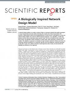
Fig. 1. Eight-legged walking robot SCORPION during a climbing test on the DARPA test site in San Antonio, TX.
During the development of biologically inspired robots, there are completely different levels, on which biology can be regarded as source of ideas. Three of these levels are treated in this paper: Outer shape and mechanical design Control of basic and more complex motions Analysis and modeling of 8-legged running The structure of this paper follows the sequence of these three topics. Finally, in the outlook further developments in motion control are briefly discussed.
The most challenging parts of a walking robot are the legs. From investigation of real scorpions we see that they walk and run with high skill on legs, each of which consists of six joints. Not all of these are active but nevertheless such a number of degrees-of-freedom is too large to handle for a robotic construction. Hence we had to reduce this number without losing too much freedom for motions. The leg presented here provides 3 degrees of freedom.
2.
3.
Mechanical design of Scorpion
In the DARPA funded project Scorpion we developed a biomimetic eight-legged walking robot (see Fig. 1). Since our ambulation control approach is also suitable for the more widely studied hexapods, we also built up a six-legged robot which is equipped with the same electronic and mechanical parts as the eight-legged version. The length of the eight-legged robot is 65 cm and the six-legged one is 52 cm long. The weight of the fully equipped robots (including 3.8 Ah rechargable batteries, communication equipment and sensors) is 9.8 kg for the
The biomimetic control approach
Our ambulation control approach combines two biological inspired concepts, which seems to be contradictory at first sight. These are the Central Pattern Generator (CPG) and the Reflex. A Central Pattern Generator is a set of biological neurons which is able to produce rhythmic motion patterns without the need of sensory feedback [2]. To model the functionality of a CPG we use Basic Motion Patterns (BMPs) and Posture Control Patterns (PCPs) to configure the output of our CPG model.
576
A BMP describes a rhythmic motion, for instance a forward movement, whereas a PCP describes a change in the posture of the system, for example to tilt forward. Because no sensory feedback is used in our current model to alter the motion produced by an active BMP, this approach would only enable the robot to walk on smooth ground without obstacles, which would disturb the motion.
4.
Modeling and Simulation
The mechanical model of the walking robot SCORPION in ADAMS(TM) consists of 43 rigid parts which are coupled by 42 joints (rotational and fixed ones). The legs of the robot are significantly different from its living prototype. Especially the number of leg segments and their joints is reduced. Nevertheless similar demands must be met regarding joint coordination and body control. During each stance the lateral distance between body and foot and the height of the body above the ground should remain constant as for the scorpion Hadrurus arizonensis [14] to avoid disturbing rolling and shaking. A mathematical solution is presented in [12].
To deal with obstacles we also included a model for reflex based control in parallel to the CPG model in our approach. Reflexes rely heavily on the sensor-motor-feedback and are in the biological archetype like CPGs provided by evolution. A widely studied and only on reflexes based locomotion approach is the “Walk Net” [1]. An example for a robot controller only based on a CPG model is the ambulation controller [3]. To control the CPGs they use a command neuron [4] like approach. The motions for lateral left, lateral right, forward and backward walking are implemented as finite state machines. The control to execute one of these finite state machines is done by a command neuron like structure.
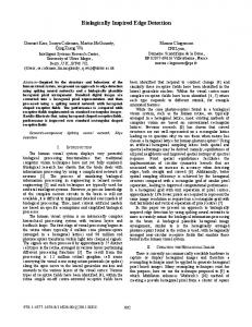
4.1 Motion patterns for real scorpions The gait of living scorpions is almost always an alternating tetrapod wave scheme (Fig. 2, left). Legs within a tetrapod, beginning with the posterior leg, step in an anteriorly directed order, with each leg lagging the preceding one by about 10% of the total cycle (phase). The other tetrapod commences the wave of promotions when the first one is half way through its cycle [11]. A cycle consists of a leg promotion period (swing) and a leg remotion period (stance). Phase, swing, stance ( Fig. 2, right), and stride length are the parameters of the robot's motion pattern.
In contrast to this our CPG model allows to be controlled by more than one entity. This means that the overall behavior of an CPG is the result of the influence of all active BMPs and PCPs on this CPG. Therefore we are using the term of combinable “Basic Motion Patterns” and “Posture Control Primitives”. This has certain implications for the control of the system. For example, it allows to move omnidirectional by activating an forward BMP and an lateral BMP with the same strength the robot would walk diagonal. It is also possible to activate an PCP to outstretch the legs, while walking and thereby changing the height of the robot. This together with the in parallel reflex system result in a walking system suitable for rough outdoor environments.
Fig. 2. Tetrapod walking gait of real scorpions (left) and an according motion pattern beginning from the start position
The approach was successfully tested in real world environment with different terrain covered with crops, sand, rocks. The system is able to overcome steps, pipes and rocks up to 30cm and can walk up 35% slopes.
(right). Vertical lines reveal how many legs are touching the ground at given times.
For scorpions, phases within a tetrapod group and between the two tetrapod groups vary around a mean value in contrast to fixed phases for the robot and its model. The intra phase increases with the slope of the ground [5]. The typical ipsilateral pattern 4-2-3-1 is replaced several times by a 4-1-2-3 pattern (Fig 3). It should be noted, that both
More detailed information and data about the implementation of the control idea, the performed tests and the SCORPION robot can be found in [16,17].
577
pattern emerge from the same gait and are just consequences of an increased phase.
p = 0.0
p = 0.1
p = 0.125
p = 0.2
remains always the same fraction of a motion cycle regardless of its duration. Important for the stability of the movement is how many feet are in contact with the ground (stance phase). A consequence of fig. 4 is their decreasing number with increased leg frequency respectively shorter motion cycles. The stability can be expressed by the swing to stance ratio Q (Fig. 5) Q = (mP P + bP ) / ((1 – mP ) P – bP ) (4) the lower the ratio, the more stable the movement. Hadrurus arizonensis at its highest speed achived about Q=1.2 which is equal to about 8 Hz. The low speed end is determined by the ratio mP /mR .
Fig. 3. Ipsilateral motion pattern for different intra phases and a phase of 0.5 between both tetrapod groups. Legs 1 and 3 belong to one tetrapod group, legs 2 and 4 to the other group.
4.2 Coupling of Swing and Stance Bowerman reports a linear change of both the promotion period TP (swing) and the remotion period TR (stance) with the time P (period) for one motion cycle [11] (Fig. 4). This relation allows us to express one variable by the other:
TP (P) = mP P + bP = mP (TP + TR ) + b P TR (P) = mR P + b R = mR (TP + TR ) + b R TR = (mR /mP )(TP – b P ) + b R
(1) (2) (3)
Since (TP +TR )=P, the parameters are dependant in the following way: mP +mR =1 and b P +bR =0ms. As a consequence a set of five parameters (e.g. TP , mP , bP , φ, and stride length) is sufficient to describe all potential states of motion. For Bowerman’s examination objectHadrurus arizonensis the mean values of the parameters are approximately mP = 0.2, b P = +45ms, mR = 0.8, b R = - 45ms. For motion control it is important to understand that swing and stance are coupled and their duration cannot change independently. Their ratio is a function of the motion cycle time. If b P = b R = 0ms, the swing/stance ratio would remain constant and the walking pattern could not change. The coupling allows smooth transitions in velocity without a loss of coordination or a change of the gait (Fig. 4).
Fig. 4. swing and stance phase duration are both linear dependent of the duration of an entire motion cycle.
To pursue the biomimetic approach the patterns are transferred to the model of the robot and the parameters are scaled appropriately [13]. According to the previous paragraph the phase φ between the legs of a tetrapod group
Fig. 5: Swing to Stance ratio Q as function of the duration of a motion cycle (curved line) and the low frequency asymptote for the parameter set of Hadrurus arizonensis
578
A “natural” candidate is fP (t) = a sin( b t ) with derivative fP ’(t) = a b cos( b t ) . Here we have two equations for the two unknowns a and b . Since the coupling is nonlinear, it can be quickly solved for a and b with Newton’s method. Alternatively (if this computation must be performed on-board with a limited micro controller) it can be simplified either by using a two-dimensional table model or by Hermite interpolation, which replaces the sinusoidal fP by a polynomial fitting curve of third degree or even of fifth degree with improved fitting of the derivatives of fP .
4.3 Optimized Swing and Stance Fitting So far the timing for swing and stance at constant speed is clear but one may observe that at each point of contact (where a foot touches the ground) the angular velocity of the horizontal joint (= upper joint for horizontal motions) is zero. That conflicts with the body’s velocity over ground and leads to undesired sliding effects of feet along the ground (see fig. 6).
Such a polynomial curve needs no iterative solving and has no principal disadvantages compared to the sine curve. We just regarded the sinusoidal approach to be more “animal-like”. The resulting swing of a leg stops its promotion in the air and moves backward w.r.t. the body until it compensates exactly the body velocity. Therefore the touchdown takes place with zero horizontal velocity w.r.t. the ground. It should be noted that a similar behaviour was observed for real scorpions [14].
Fig. 6. The robots trace while walking on a plane
To avoid sliding feet we derived a fitting technique for swing and stance to adapt to the robot’s velocity: fP and fR denote swing and stance parts of joint angle f(t). Stance: Assuming that the body is moving straight forward at a certain speed, the horizontal joint must move according to a “tangens law”: fR (t) = - arctan( c t ) with t from [-TR /2, TR /2]. The joint should always support exactly the current motion of the robot without acceleration or deacceleration. The coefficient c can be easily determined from this equation if the ext reme values for fR are known. Hence we know value and first derivative of fR for the “point of losing ground contact”, where fP must be fitted to fR . Swing: We have to build a function fP that starts with the given value and derivative from the extreme values of fR and performs a swing motion as shown in the diagram:
In the resulting simulations the effect of sliding feet was significantly reduced after inserting the optimized gait using fP and fR . Nevertheless on the real robot the sliding of feet cannot be totally avoided and therefore a feedback for direction control has, of course, to be imple mented.
4.4 Eight-legged-walking with different speeds Now an interesting question is whether the walking speed of scorpions is correlated to their stride frequency respectively to the duration of one cycle (of promotion and remotion). Bowerman analyzed a dozen walking sequences and concluded: “The two parameters (walking speed and duration of a cycle) are negatively correlated in an a pproximately linear manner. Consequently, the shorter the interval duration, the higher the rate of forward velocity.” [11]. The walking speed v is the product of stride length l and stride frequency (v = l x f) . The stride frequency is inversely proportional to the duration of a cycle (f = l / (TP +TR) ). Bowe rman’s linear approach (fig. 8, straight line) v =m(TP +TR ) + b with m