Hindawi Publishing Corporation International Journal of Distributed Sensor Networks Volume 2016, Article ID 8242497, 17 pages http://dx.doi.org/10.1155/2016/8242497
Research Article Bionic Optimization Based Stability and Congestion Aware Routing Algorithm for Airborne Highly Dynamic Network Yunlong Yu, Le Ru, Sheng Mao, Kangning Sun, Qiangqiang Yu, and Kun Fang Aeronautics and Astronautics Engineering College, Air Force Engineering University, Xi’an 710038, China Correspondence should be addressed to Yunlong Yu;
[email protected] Received 9 September 2015; Revised 18 January 2016; Accepted 19 January 2016 Academic Editor: Pascal Lorenz Copyright © 2016 Yunlong Yu et al. This is an open access article distributed under the Creative Commons Attribution License, which permits unrestricted use, distribution, and reproduction in any medium, provided the original work is properly cited. Airborne highly dynamic ad hoc UAV network has features of high node mobility, fast changing network topology, and complex application environment. The performance of traditional routing algorithms is so poor over aspects such as end to end delay, data packet delivery ratio, and routing overhead that they cannot provide efficient communication for multi-UAVs carrying out missions synergistically. A bionic optimization based stability and congestion aware routing algorithm—BSCAR algorithm—is proposed to solve these problems. This algorithm integrates biological behavior and dynamic source routing algorithm, which can sense the congestion level of routes and the stability of routes. Ant colony optimization algorithm and the mathematical model of Physarum’s behavior exert effort in the process of route discovery and maintenance. The level of pheromone in routes is chosen as a standard to choose route and calculated by the mathematical model of Physarum’s behavior. A new volatilization mechanism of pheromone is also introduced into the algorithm. Meanwhile, the algorithm can make adjustment to the variance of UAV formation to prevent the compromise of the network performance. The simulation results show that the BSCAR algorithm has superiority over traditional algorithms and it is dependable in battlefield environment.
1. Introduction The recent years have witnessed a wider application of UAVs, covering many fields for military and civilian purpose. UAVs also play a significant role in modern warfare, implementing a variety of missions including reconnaissance, surveillance, information gathering, communication relay, and fast attacking. The modern warfare is characterized by fierce conflicting, wide coverage, and large amount of information, and a single UAV would be unable to meet the demands of it; thus multi-UAVs cooperative combat becomes a focus of current researches. Flight formations are usually designed for multiUAVs to implement missions cooperatively. An ad hoc UAV network can be applied to interchange data concerning mission planning, flight status, and information when multi-UAVs perform tasks in flight formation, which improves the situation awareness of the UAV formations, making multi-UAVs cooperatively implementing missions possible. The ad hoc UAV network is a branch of aeronautical ad hoc network, which is a classic application of MANET in aviation field. The network ensures UAVs log
in and out fast during war time; every UAV is designed to withhold an equal status in the network to enhance its robustness. In ad hoc UAV network, each UAV is regarded as a node. However, ad hoc UAV network has the features of greater node mobility, faster network topology variance, more complicated appliance situations, and more frequent data interaction than mobile ad hoc network. These features have brought big challenges for the design of routing algorithm in ad hoc UAV network. Traditional routing algorithms are unable to satisfy the demands of multi-UAVs carrying out missions cooperatively in this situation, and the routing algorithms based on QoS can only be applied under certain circumstances, so in order to meet the demands of multiUAVs carrying out missions cooperatively in complicated communication situations, a routing algorithm which is appropriate for ad hoc UAV network is required. We believe that the routing algorithm for ad hoc UAV network is supposed to obtain such properties: (1) low end to end delay; (2) low data packet loss probability; (3) high reliability; (4) no congestion; (5) low routing overhead;
2
International Journal of Distributed Sensor Networks
Nest
Food
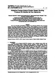
Figure 1: The schematic diagram of ACO algorithm.
and (6) maintaining of the network performance by adjusting the routing algorithm for the variance of formation. Traditional routing algorithms are unable to meet the above requirements. We summarized the three keys to designing the algorithm: the route length, the congestion level of a route, and the stability of a route. They should be taken into comprehensive consideration to design the routing algorithm for ad hoc UAV network. Meanwhile, we assume that every node has enough energy in ad hoc UAV network, so the energy is not the factor which can influence the performance of routing. The ant colony optimization (ACO) algorithm was proposed by the Italian scholar Dorigo in 1992; it is a heuristic algorithm, which imitates the nature process of ants searching for food [1]. The ant colony is able to determine the shortest route between their nest and the food source, and the following ants can find the route by a chemical material (pheromone) to find food [2]. As is shown in Figure 1, each ant comes out of the nest in a random direction in the searching stage, and different ants get to the food source in different routes; when returning, all ants followed their original routes and release pheromone, which is in negative correlation with route length. With the passage of time, the pheromone in the optimal route is accumulated because of constant passage of ants, while the pheromone in other routes is volatilized or diluted because of the rare number of ants passing them. A series of combinatory optimization problems can be solved by ACO algorithm [3], and it is applied to wireless network routing in various ways. There exist examples to prove that the routing algorithms which are based on ACO algorithm have an advantage over traditional routings in terms of network performance [4]. For dynamic source routing (DSR) algorithm [5], when the source node sends data package to destination node, the source node needs to determine whether there exist routes qualified to complete the transmission at first; if not, the source node broadcasts the RREQ message in the network through the way of flooding until the destination node receives the message; during this process, the intermediate nodes are recorded in RREQ message in order. After receiving the RREQ message, the destination node would send RREP message along the original route. The shortest route would be used to transmit data. In route maintaining phase, when an intermediate route is disconnected, the current node would send the route failure message to the source node through the upstream node, and the source node would update accessible routes. However, the DSR algorithm has many disadvantages: firstly, the mobility of nodes leads to obvious link breakage, which significantly increases the package loss rate; secondly,
the flooding mechanism adopted in this algorithm increases the routing overhead and end to end delay. In recent years, the Physarum has become a new focus of Physarum-inspired method. Physarum polycephalum is composed of tubular form and flowing fluid. The flowing fluid can transport nutrition and transmit signal for each of the several parts of Physarum polycephalum; at the same time, it also can adjust the change of tubular form [6, 7]. The mathematical model of Physarum’s behavior can help us select appropriate routes. We integrate the DSR algorithm and biological behavior and propose a bionic optimization based stability and congestion aware routing algorithm—BSCAR algorithm— after making many improvements. This routing algorithm basically reaches the proposed requirements and is able to satisfy the needs of sharing information when multi-UAVs implement missions cooperatively. The contributions of this paper are concluded as follows: (1) A route stability measurement method is proposed and a long-acting supervision mechanism is established, which greatly improves the measurement accuracy. (2) A method measuring congestion level of a route is proposed, which is followed by a nonlinear processing to enable the results to be fit for real situations. (3) The route discovery and choosing process of DSR algorithm are improved based on ACO algorithm and the mathematical model of Physarum’s behavior, which significantly improves its performance and makes it possible to adjust to the changing formation of UAVs. (4) We improve the mechanism of pheromone volatilization through different routes using different decay coefficients, which decreases the routing overhead. (5) In the simulation environment, the BSCAR algorithm has superiority over other main routing algorithms. The rest of the paper is organized as follows: Section 2 is about the related works. So, we select and summarize some papers which have the same issue. We describe the data structure of two control packets in Section 3. The proposed mechanism to estimate the stability of a route is detailed in Section 4. The proposed mechanism to estimate the congestion level of a route is described in Section 5. Section 6 is about the BSCAR algorithm. The performance evaluation of the proposed algorithm is included in Section 7. Finally, we conclude our work in Section 8.
2. Related Works In recent years, the routing protocols of aeronautical ad hoc network have been diversified. The protocols can be put into three categories based on the different routing information renewal mechanisms: (1) table driven (proactive) routing protocols, such as DSDV [8], FSR [9], STAR [10], OLSR [11], WRP [12], and TBRPF [13]. In proactive routing protocols, every node is required to maintain one or several
International Journal of Distributed Sensor Networks routing tables, which contain the consistent and latest routing information in relation to other nodes in the network. To maintain such routing tables, each node needs to broadcast renewal routing information periodically, thus maintaining and memorizing the network topology and the node routing information. The table driven routing protocols have the advantage of low end to end delay and superior service quality during the network transmitting process. However, the protocols are costly, and a large number of routing control packages would greatly increase the routing overhead and the congestion level of nodes; (2) demands based (reactive) routing protocols, such as AODV [14], DSR [5], TORA [15], and SSR [16]. In reactive routing protocols, new routes are searched only when demand for communication exists. The routing overhead is relatively low and the network resource is saved due to the lack of necessity to broadcast renewal routing information; however, if there exist no available routes connecting the target node when the source node demands communication, a new search process is forced to be created and the data transmission could be delayed; (3) hybrid routing protocols, such as ZRP [17]. This kind of protocols integrates the previous two kinds but still could not solve the problem of overlarge routing overhead. With the development of ant colony optimization algorithm, it is increasingly adopted to solve the routing problems in mobile ad hoc network. According to [18], the routing protocols based on ACO algorithm can be put into three categories. We illustrate the protocols which are representative and related to our work. In Ant-DSR algorithm [19], unicast ant agent is used to establish and update routings; the other ant agents are used to detect neighbors. The method is a proactive routing algorithm; it can shorten the data transmitting delay but still cannot avoid the increase of routing overhead, which leads to congestion in the network. The Ant-Based Control (ABC) [20] algorithm is proactive and it can adapt to highly dynamic MANETs due to its high robustness to node failure. In this algorithm, the link with the most pheromone in the column corresponding to the destination can be selected by exploratory ants. But the best route is easy to get congested. The probabilistic ant routing (PAR) algorithm [21] has two kinds of agents—forward and backward ants. The forward ant explores the network to collect the traffic information. When the forward ant reaches the destination, it is deallocated and the backward ant inherits the stack contained in the forward ant. Each node is assigned a probability of 1/𝑁, where 𝑁 is the number of neighbors of a node. However, it cannot adapt to large network. In ADSR algorithm [22], the forward ant and backward ant are used in routing discovery phase, and it belongs to reactive routing algorithms. ADSR takes into consideration three QoS parameters, namely, delay, jitter, and energy. However, the reliability of routes is not evaluated in the ADSR algorithm, and intermediate link breakage tends to frequently occur in high mobility ad hoc UAV network; thus the data packet delivery ratio is decreased. The probabilistic emergent routing algorithm (PERA) [23] has the routing table which stores the probability distribution for the neighbors. This probability associated with a neighbor reflects the likelihood
3 of that neighbor forwarding and delivering the packet to the destination node. This scheme can be seen as the integration of the DSR and ACO algorithms. The drawback of this algorithm is that there is no result from passing packets, that is, no caching. The improvised ant colony optimization algorithm for MANETs (PACONET) [24] has two kinds of mobile agents. FANTs are transmitted to determine new routes. BANTs establish the path based on the information gathered by FANTs. These mobile agents leave certain amount of pheromone at the time they depart from the node. The data packets are routed stochastically on the path that has the highest pheromone value along the path to destination. But its overhead is too high. HOPNET algorithm [25] and HRAZHLS algorithm [26] are both hybrid routing algorithms; four kinds of ants are included in the algorithms: intrazone forward ant, intrazone backward ant, interzone forward ant, and interzone backward ant. But the HOPNET algorithm lacks the expansibility for large-scale networks and is only adapted to small ones. The routing overhead of HRAZHLS algorithm is relatively large. More overhead is also AntHocNet’s [27] main drawback. Ant routing algorithm for MANETs based on adaptive improvement (ARAAI) [28] has two tables. One contains initial node, last node, and heuristic value. The other contains the information of neighbors which represents the connection between the current node and other nodes. The FANT chooses next hop after considering both pheromone value and local heuristic value of the link. However, the route discovery delay is too high. In summary, whether integrated with ACO algorithm or not, the proactive routing protocol, the reactive routing protocol, and the hybrid routing protocol cannot meet the demands for ad hoc UAV network. Meanwhile, the above routing algorithms cannot efficiently avoid the common problems in mobile ad hoc network, such as node congestion and link breakage, which could greatly increase package loss rate. In order to measure the stability of a route, the stability of links in the route must be measured at first. There mainly exist two kinds of methods determining the link stability. Firstly, for the methods based on distance [29, 30], they are set up upon the criterion that the closer the distance is, the better the stability would be, and the distance is calculated by the GPS or the signal-power of received “Hello” message. This method is single in form and is unable to establish a long-effective supervisory mechanism. If adopting this method, it would be inevitable to bring positioning error and external GPS interfering signal, which leads to failure in determination. Secondly, for the methods based on mobility of nodes, they consist of two branches. One is to calculate the movement direction and velocity of nodes through the positioning information [31] or the Doppler frequency shift of “Hello” message; thus the link stability can be evaluated; however, the computing cost is relatively large, and GPS error is easy to be brought in the network if using the positioning information. The other is to evaluate the stability based on probabilistic methods; the method adopted in [32] is too complicated with large computing cost; [33] evaluates the link stability through
4 the variation of neighbor nodes’ numbers, which is inaccurate with big error; the computing method in [34] is relatively easy, but the generated links with high stability could locate in the margin of communication range, which are prone to disconnection. The literatures addressing the network congestion proposed many solutions, but there still exist some inadequacy. In [35], the traffic load is represented by the ratio of the interface queue length in the MAC layer to the total length of interface queue, thus avoiding the heavy load node from being an intermediate node and causing network congestion; however, the process of measuring the congestion level of a route is insufficient. In [36], the evaluation of the route congestion level is based on buffer occupancy, channel load measurement, and package drop rate, but it puts the low energy cost in the first place, leading to inaccurate measurement of route congestion level. The papers above consider the stability of a route or the congestion level of a route separately and never combine them. In [37], the measurement of route stability is combined with the evaluation of route congestion, which avoids the common problems in mobile ad hoc network; however, the method in this paper needs to be improved. Tero et al. [6, 7] proposed a mathematical model for the behavior of Physarum polycephalum. Zhang et al. [38, 39] introduced the mathematical model of Physarum polycephalum’s foraging behavior into the field of wireless sensor network and then used the modified model to select node as the next hop. At present, no literature uses this model in airborne highly dynamic ad hoc UAV network. We propose a routing algorithm for ad hoc UAV network, which can fulfill the requirements, such as low end to end delay, high package delivery ratio, and low routing overhead. It also can avoid some common problems, such as link breakage and node congestion. Meanwhile, the routing algorithm can adapt the variance of UAV formation. Eventually, the routing algorithm we proposed overcomes all the deficiencies of the traditional routing algorithms.
3. Definition of the Control Packet Format There mainly exist two kinds of routing control packets in mobile ad hoc network (RREQ and RREP). RREQ (Route Request) control packet consists of the address and serial number of destination node, the serial number of broadcast, the address and serial number of source node, the address of the previous hop in route and the number of hops, and so forth. RREP (Route Reply) control packet consists of the address of source node, the address and serial number of the destination node, the number of hops, survival time, and so forth. Many improvements have been made based on the integration of biological behavior and DSR algorithm, and the data structure of RREQ and RREP must be modified to be fit for the proposed routing algorithm, which is shown in Figure 2. The two kinds of modified routing control packets are named after RREQ.Ant, RREP.Ant; they are also referred to as the forward ant and backward ant. The modified data structure is shown in Figure 2.
International Journal of Distributed Sensor Networks
Source node address Destination node address HC
RC
a
RS
Type
Intermediate node address Intermediate node 1 Intermediate node 2 .. .
Figure 2: The format of the control packet.
The addresses of the source node and destination node are MAC address instead of IP address, which prevents the case when nodes disconnect from the network and IP address cannot be assigned to them. HC stands for the number of hops in the route connecting source node and the destination node in RREQ.Ant, and the value of HC is initially set as 0. However, HC is set as a constant in RREP.Ant. RC and RS are referred to as congestion level and stability of the route connecting source node and destination node, and the value of “a” is effective only in RREP.Ant, which is used to determine the transmitting route of backward ant. “Type” represents the type of routing control packets, which is set to be RREQ.Ant when Type = 1 and RREP.Ant when Type = 0. The last part is used to store the addresses of intermediate nodes in the route connecting the source node and destination node.
4. Sensing the Stability of a Route In ad hoc UAV network, the link breakage is a common phenomenon because of the changing network topology, which is the result of the high speed and different missions of UAVs. A method evaluating the stability of links is proposed in this paper to avoid the compromise of the network performance caused by network disconnection. This method is established upon the signal strength of the received “Hello” message and the corresponding supervisory mechanism. The method can improve the performance of network by predicting and deleting the possible disconnecting links after comprehensively evaluating the stability of a certain link. Meanwhile, the positioning information is not adopted in this paper to avoid the possible influence caused by GPS positioning error or external GPS interfering signal. When implementing reconnaissance mission under warfare environment, the UAV formation is composed of different kinds of aircrafts for the requirements of different missions; therefore, the velocity, the antenna gain, and the maximum transmitting power of each platform are different. The data packet format of “Hello” message is improved in this paper, which includes the address of source node, node congestion level, antenna gain, transmitting power, and speed. According to the free space attenuation model [40], the received signal strength 𝑃𝑟𝑖 of the “Hello” message in current
International Journal of Distributed Sensor Networks
5
node transmitted from the neighbor node 𝑖 in a distance 𝑑 is 𝑃𝑟𝑖 = 𝑃𝑡 𝐺𝑡 𝐺𝑟 (
𝜆 2 ) , 4𝜋𝑑
(1)
where 𝜆 is the length of radio wave, 𝐺𝑟 is the receiving antenna gain, 𝐺𝑡 is the transmitting antenna gain, and 𝑃𝑡 is the transmitting power of “Hello” message from neighbor node. We assume that the covering range of antenna is a circular region whose radius is 𝑅. The average distance between two moving nodes in a circular region with radius of 𝑅 is 0.9054R according to [41]. Hence the threshold value of received “Hello” message signal strength from neighbor node is defined as 𝑃threshold 𝑖 = 𝑃𝑡 𝐺𝑡 𝐺𝑟 (
2 𝜆 ) . 4𝜋 × 0.9054𝑅
(2)
The threshold value of received signal strength can be calculated based on the known information of current node and the information included in the “Hello” message transmitted from neighbor node, and the initial judgment of link stability can be made after comparing the threshold value with the measured signal strength. The processes are as follows: 0, if 𝑃𝑟𝑖 ≤ 𝑃threshold 𝑖 , { { LS𝑖 = { {1 − 𝑃threshold 𝑖 , if 𝑃𝑟𝑖 ≥ 𝑃threshold 𝑖 . 𝑃𝑟𝑖 {
(3)
The value of LS𝑖 represents the current stability of the link 𝑖; the greater the value is, the better the stability of the link would be, but the value cannot exceed 1. A link would be deleted from the cache if the LS𝑖 value of it is 0 and considered as an unstable link. Constant updates are needed to keep the instantaneity of LS𝑖 , and the interval (the period of broadcasting “Hello” message) 𝑡 is 𝑡=
𝑅 − 0.9054𝑅 , 𝑉1 + 𝑉2
(4)
where 𝑉1 refers to the maximum movement velocity of current node and 𝑉2 refers to the maximum movement velocity of the neighbor nodes. The corresponding 𝑡 differ from each other because of the different types of neighbor nodes. Renewing the value of LS𝑖 by adopting the time interval guarantees the fact that the neighbor nodes in cache locate in the communication range during time span 𝑡, thus effectively taking advantage of the storage space and providing reliable options for the route discovery phase. This process effectively solves the deficiency of the fixed period of “Hello” message. The above process only evaluates the stability of links at a certain moment, which lacks a long effective mechanism for comprehensively evaluating the stability of links. Therefore, the mobility of neighbor nodes is estimated and the nodes in cache with high mobility are deleted according to the signal strength variation of “Hello” message at different moments in our work.
The Bienayme-Chebyshev inequality [42] is as follows: 𝑃 {|𝑋 − 𝐸 (𝑋)| < 𝜀} ≥ 1 −
var (𝑋) , 𝜀2
(5)
where 𝑋 is a discrete variable, 𝐸(𝑋) is the expectation value of 𝑋, var(𝑋) is the variance of 𝑋, and 𝜀 is an arbitrary positive number. If var(𝑋) = 0, then 𝑃{|𝑋 − 𝐸(𝑋)| < 𝜀} = 1, which means that the variable 𝑋 is equal to its expected value, which also means that the smaller the variance of 𝑋 is, the closer 𝑋 would be to its expected value and the smaller the varied quantity of 𝑋 would be. According to multiple measurements of 𝑋, the variance var(𝑋) is 2
var (𝑋) = (∑ 𝑘
𝑋𝑘 2 𝑋 ) − (∑ 𝑘 ) . 𝑛 𝑛 𝑘
(6)
Take the values of LS𝑖 at different moments as the multiple measured values of 𝑋 and substitute them into (6): 𝑛
2
2
𝑛 LS𝑖 (𝑡𝑚 ) LS (𝑡 ) ) − (∑ 𝑖 𝑚 ) . 𝑛 𝑛 𝑚=1 𝑚=1
var (LS𝑖 ) = ( ∑
(7)
The mobility of a neighbor node can be gained according to (7), and the smaller the var(LS𝑖 ) is, the less mobility of the node shows and the more stable the link 𝑖 would be. This method only applies for determining the mobility of the neighbor nodes in the cache of the current node. In summary, the procedures to determine the stability of a link are as follows: encode all nodes within the range of 0.9054𝑅 as number for each node, write them into the cache, and calculate the current stability LS𝑖 of each link according to (3) at set interval. Delete the links from the cache whose value of LS𝑖 is 0. Determine the mobility of a link when it gains two nonzero LS𝑖 in a row and conduct constant judgment for a link as long as LS𝑖 is not zero. If the var(LS𝑖 ) of a certain link exceeds the previously set threshold value varthreshold third cumulatively, it means that the mobility of its neighbor nodes is high and the link is unstable; thus the link would be deleted from the cache of the current node. Meanwhile, for the sake of saving storage space, only five recent measured values of LS𝑖 can be stored in the cache. The number of nodes which is written into the cache is not limited. In route discovery phase, the most stable route is usually chosen to transmit data, and the stability of the current link is supposed to be quantified comprehensively. A comprehensive quantifying method for measuring the stability of the current link is proposed as follows: CLS𝑖 (𝑡𝑚 ) =
LS𝑖 (𝑡𝑚 ) , 𝑒var𝑚 (LS𝑖 )
(8)
where CLS𝑖 (𝑡𝑚 ) is the comprehensive stability of the link 𝑖 at moment 𝑡𝑚 ; LS𝑖 (𝑡𝑚 ) is the value of LS𝑖 at moment 𝑡𝑚 ; var𝑚 (LS𝑖 ) is the value of var(LS𝑖 ) at moment 𝑡𝑚 . The value of var(LS𝑖 ) is set to be empty when a neighbor node enters the cache for the first time at the moment,
6
International Journal of Distributed Sensor Networks
and we set var𝑚 (LS𝑖 ) = 1 at the moment. And the bigger the value of CLS𝑖 (𝑡𝑚 ) is, the higher the comprehensive stability of the link would be. In our work, each route control packet includes a RS value, which is calculated by route request control packet in the route discovery process. A forward ant departs from the source node and the initial value of RS is set as 1. When the forward ant moves in the network, the RS value would be renewed by the product of the current value of RS and the link stability CLS𝑖 between the intermediate node and the previous node. When the forward ant arrives at the destination node, the stability of the route between the source node and the destination node can be gained: RS =
𝑛
𝑗 ∏CLS𝑖 , 𝑗=1
(9)
𝑗 where CLS𝑖
is the stability for each link passed by the forward ant in route discovery phase and 𝑛 represents the number of passed nodes.
Busy
MAC layer to the total length of interface queue in MAC layer is bigger than 65% [43], so we adopt nonlinear to process Ave BO𝑖 (𝑡), making it fit for practical needs: 5
NBO𝑖 = 1 − (1 − Ave BO𝑖 (𝑡)) ,
BO𝑖 =
𝑄𝑖 , 𝑄max
(10)
where 𝑄𝑖 is the interface queue length in MAC layer of node 𝑁𝑖 and 𝑄max is the total length of interface queue in MAC layer. The value of BO𝑖 in node 𝑁𝑖 is measured periodically to calculate the average buffer occupancy Ave BO𝑖 (𝑡) during a certain period of time. 𝑁 times of measurement are assumed to be carried out during time 𝑡: Ave BO𝑖 (𝑡) =
∑𝑁 𝑗=1 BO𝑖 (𝑗) 𝑁
,
(11)
where BO𝑖 (𝑗) is the 𝑗th measurement result of BO𝑖 for node 𝑁𝑖 . In general, a node is determined to be in high buffer occupancy when the ratio of the interface queue length in
(12)
where NBO𝑖 is the nonlinearized average buffer occupancy of node 𝑁𝑖 . 5.2. Channel Load. According to [37], the channel load CL𝑖 can be obtained after channel sampling over certain time span periodically. The sampling process is shown in Figure 3:
5. Sensing the Congestion Level of a Route
5.1. Buffer Occupancy. The ratio of the interface queue length in MAC layer to the total length of interface queue in MAC layer represents the current buffer occupancy (BO𝑖 ) of node 𝑁𝑖 , which can be calculated as follows:
Idle
Figure 3: The sampling process for channel load measurement.
CL𝑖 = When multiple UAVs implement surveillance mission to hot spot areas in formation, much target data need to be shared and transmitted to the base station. Network congestion would frequently occur if traditional routing algorithms are adopted to construct routes transmitting data. The network transmission performance would be compromised if network congestion occurs in ad hoc UAV network, such as increasing packets loss rate or average end to end delay. We propose a method measuring the congestion level of a route, and it is measured based on buffer occupancy and channel load; the nonlinear processing is adopted to make the results fit for real situations.
Busy
Idle
𝑁busy 𝑁busy + 𝑁idle
,
(13)
where 𝑁busy represents the times when the channel is busy during the span, while 𝑁idle represents the times when idle. With the increase of channel load CL𝑖 , the congestion is getting worse. We conducted many consecutive measurements for CL𝑖 and obtained the average channel load during time 𝑡: Ave CL𝑖 (𝑡) =
∑𝑁 𝑗=1 CL (𝑗) 𝑁
(14)
,
where CL𝑖 (𝑗) is the measurement result of CL𝑖 in the 𝑗th time and 𝑁 is the measuring times during time 𝑡. In most cases, the value of 𝑡 is set to be 30 s, and the measurement time is 5 to 10 s. The results of channel load require nonlinear processing, which is similar to that of buffer occupancy. We believe that the channel load is high when it is greater than 0.7. The nonlinear processing is as follows: 4
NCL𝑖 = 1 − (1 − Ave CL𝑖 (𝑡)) .
(15)
The following equations are defined to comprehensively evaluate the congestion level of a certain node: 𝑀𝑖 (𝑡) =
NBO𝑖 + NCL𝑖 , 2
(16)
CNC𝑖 (𝑡) = ] × 𝑀𝑖 (𝑡 − 1) + (1 − ]) × 𝑀𝑖 (𝑡) , where 𝑀𝑖 (𝑡) is the node congestion level during current time window, ], (1−]) are the node congestion level weight factors assigned to the previous and current time windows, and CNC𝑖 (𝑡) represents the comprehensive value of current node congestion level. Each route control packet has a RC value, which is calculated and obtained during the route discovery process. A forward ant departs from the source node and establishes
International Journal of Distributed Sensor Networks
7
the route from the source node to the destination node; when the forward ant arrives at the destination node, the maximum node congestion level CNC𝑖 (𝑡) of all nodes in the route is defined as the congestion level RC of the route: RC = max (CNC𝑖 𝑗 ) ; ∀𝑗 = 1 . . . 𝑛,
(17)
where CNC𝑖 𝑗 represents the congestion level of each node passed by forward ant during route discovery process and 𝑛 represents the number of nodes passed by the forward ant.
6. Bionic Optimization Based Stability and Congestion Aware Routing Algorithm 6.1. Route Discovery Process. There exist multiple kinds of formation for UAVs based on different missions. This paper focuses on how the density of UAVs in formation affects the routing of ad hoc UAV network. Therefore, this paper proposes two kinds of route discovery algorithm according to the density of nodes in ad hoc UAV network. According to [44], we consider that the UAV formation is concentrated when ANP (Average Network Partitioning) is fewer than 3%, or it is considered as sparse formation. The difference of the two algorithms lies in the broadcasting scheme of RREQ.Ant, and the remaining aspects are the same. 6.1.1. RREQ.Ant Delivery (1) Sparse Formation. When a UAV acquires the target information and needs to share the information to other UAVs, the current node firstly makes comparison among the existing routes in cache; if there exist routes which are able to accomplish the information transmission, the optimal route would be chosen to transmit the target information according to the route choosing process; if there does not exist qualified routes to transmit target information, the route discovery process would be started, thus sending forward ants to all stable nodes in its neighborhood. Compared with the flooding method proposed in [45], the method proposed in this paper can overcome the disadvantage (such as no directivity and blindness) of flooding method, which can improve the dependability of the discovered routes. When an intermediate node receives the forward ant from the previous node, the hop number HC in the control packet is first to be determined. The maximum value of HC is 127 with the limit of storage space; once the maximum value of HC is discovered, the intermediate node would delete the packet to prevent the distance measuring error. Secondly, a preventive mechanism is proposed in this paper to avoid the unfavorable effect caused by route circle to the ad hoc UAV network. When an intermediate node discovers the node address of itself in the INA, the route discovery process is considered to be in circular status. Firstly, the RREQ.Ant is modified and the nodes entering the circle would be deleted; subsequently, stable nodes from the neighborhood which would not enter a circle can be chosen, and RREQ.Ant would be transmitted to them.
Finally, if there is not circular problem, the current intermediate node will look for qualified routes which can arrive at destination node in its cache, if there exist such routes, the corresponding information in the forward ant needs to be renewed (the number of hops, the stability, the congestion level, etc.) and route reply process would be started; this method can decrease the end to end delay and route overhead; if there do not exist such qualified routes, the current intermediate node would renew the current forward ants and broadcast them to the stable neighbor nodes. For destination node, if receiving RREQ.Ant, it needs to be renewed. Meanwhile, the route reply process is started. (2) Concentrated Formation. For concentrated formation, if adopting the same routing algorithm as sparse formation, with the increase of node density, the broadcasting number of RREQ.Ant would significantly increase, thus tending to cause broadcast storm and compromise the performance of network. Hence, two modifications are made in the routing algorithm of concentrated formation. The first is to attach the list of stable neighbor nodes of the current node to previous Hello message; the second is to modify the broadcasting scheme of forward ant. Inspired by [44], a probabilistic broadcasting scheme is proposed to reduce the number of RREQ.Ant and decrease probability of occurring of the broadcast storm. Meanwhile, this scheme guarantees the redundancy of discovered routes, which can be reliable in battlefield environment. The probabilistic broadcasting scheme can be only applied to intermediate nodes, and the forward ant broadcasting scheme of sparse formation is still applied to source node to ensure the redundancy of discovered routes. When an intermediate node 𝐷 receives the forward ant from the previous node 𝐹, a comparison would be made between the list in Hello message of node 𝐹 and the current list, thus calculating the broadcasting probability 𝑝 of forward ant; and the node 𝐷 would broadcast the renewed forward ant to stable neighbor nodes under probability 𝑝. The equation calculating the broadcasting probability is as follows: 𝑝=
𝑛+𝑞 , 𝑚+𝑛+𝑞
(18)
where 𝑚 is the number of mutual stable neighbor nodes of the two nodes; 𝑛 means the number of stable neighbor nodes belonging to node 𝐹 while not belonging to node 𝐷; and 𝑞 means the number of stable neighbor nodes belonging to node 𝐷 while not belonging to node 𝐹. Although the modification made to Hello message in this section increases the occupied time of wireless media, the probabilistic broadcasting scheme can significantly decrease the number of forward ants, thus decreasing the routing overhead and guaranteeing the dependability of the discovered routes. Above all, it does more good than harm. The pseudocode of the RREQ.Ant delivery algorithm is shown in Algorithm 1. 6.1.2. RREP.Ant Delivery. When the destination node receives RREQ.Ant, it transforms the type of route control packet
8
International Journal of Distributed Sensor Networks
RREQ.Ant Delivery () { To Source Node: % Source node 𝐴 sending data packet 𝐵 to destination node 𝐶. 𝑋 ← 0; If there are feasible paths found between 𝐴 and 𝐶 { 𝑋 ← route selection(); 𝐵 is sent through path[𝑋]; } If (𝑋 = 0) { Broadcast RREQ.Ant; } To Intermediate Node: % Intermediate node 𝐷 receiving a packet 𝐸 from node 𝐹. If receives packet { If (𝐷 ≠ destination address) { If (type = 1) { loop ← 0; If (HC = 127) { Discard the packet; } For 𝑖 = 1 to end { If (INA[𝑖] = 𝐷) { loop ← 1; break; } Else Continue; } If (loop = 1) { For 𝑗 = 𝑖 + 1 to end { 𝐴[𝑘] ← INA[𝑗]; INA[𝑗] ← 0; } 𝑖 ← 0; For 𝑛 = 1 to end { For 𝑘 = 1 to end { If (link[𝑛] ≠ 𝐴[𝑘]) 𝑖++; } If (𝐼 = 𝑘max ) RREQ.Ant is forward to link[𝑛]; } } If (loop = 0) { If there are feasible paths to 𝐶 Algorithm 1: Continued.
International Journal of Distributed Sensor Networks
{
9
𝑋 ← route selection (); RC ← max {RC[𝑋], RC, CNC[𝐹]}; RS ← RS ∗ RS[𝑋] ∗ CLS[𝐹]; a ← HC; HC ← HC + HC[𝑋] + 1; INA ← path[𝑋]; RREP.Ant Delivery ();
} If no route is found { HC ← HC + 1; RS ← RS ∗ CLS[𝐹]; RC ← max {RC, CNC[𝐹]}; Broadcast RREQ.Ant; } } }
} } To Destination Node: % Destination node 𝐶 receiving a packet 𝐻 from node 𝐼. If receives packet { If (destination address = 𝐶) { If (type = 1) { HC ← HC + 1; RS ← RS ∗ CLS[𝐼]; RC ← max {RC, CNC[𝐼]}; RREP.Ant Delivery (); } } } } Algorithm 1: The pseudocode of the RREQ.Ant delivery algorithm.
into RREP.Ant and returns to the source node along the previous routes. For intermediate nodes, when receiving RREP.Ant, they only need to transmit it along the route; when receiving RREQ.Ant and finding the route connecting the destination node, they need to transform the type of route control packet into RREP.Ant and return to the source node along the previous routes, too. When the source node receives RREP.Ant, it starts the route choosing process, and the optimal route would be chosen to transmit target data. The pseudocode of the RREP.Ant delivery algorithm is shown in Algorithm 2. 6.1.3. Route Selection. On the basis of the literature [6], we can get the foraging model of Physarum polycephalum: 𝑄𝑖𝑗 =
𝜋𝑟𝑖𝑗4 (𝑃𝑖 − 𝑃𝑗 ) 8𝜂𝐿 𝑖𝑗
=
𝐷𝑖𝑗 (𝑃𝑖 − 𝑃𝑗 ) 𝐿 𝑖𝑗
=
𝐷𝑖𝑗 Δ𝑃𝑖𝑗 𝐿 𝑖𝑗
,
(19)
where 𝑄𝑖𝑗 is the flux through the tube, Δ𝑃𝑖𝑗 = 𝑃𝑖 − 𝑃𝑗 is the difference of pressures, 𝑟𝑖𝑗 is the radius of the tube, 𝜂 is
the viscosity of the fluid, 𝐷𝑖𝑗 = 𝜋𝑟𝑖𝑗4 /8𝜂 is a measure of the conductivity of the tube, and 𝐿 𝑖𝑗 is the length of the tube. In [38, 39], the mathematical model of Physarum polycephalum can select the appropriate routes which is used for data transmission. We improve this model, which can make it conduct route selection in ad hoc UAV network. We replace 𝐷𝑖𝑗 by the link quality Φ. Δ𝑃𝑖𝑗 is replaced by RS and RC. 𝐿 𝑖𝑗 is ̂ 𝑄𝑖𝑗 is replaced by replaced by the normalized hop count HC. the pheromone level of a route. For each backward ant which is received by the source node, the source node would extract value of HC, RC, and RS to calculate the pheromone level of the route, which is calculated as follows: Pheromone level of a route =
Φ × (𝑘 × RS + (1 − 𝑘) × (1 − RC)) , ̂ HC
(20)
where 𝑘 is a coefficient satisfying 0 < 𝑘 < 1. The value of Φ is usually set as 1.
10
International Journal of Distributed Sensor Networks
RREP.Ant Delivery () { To Destination Node: If receives RREQ.Ant { a ← HC − 1; type ← 0; 𝐴 ← Destination address; Destination address ← Source address; Source address ← 𝐴; Send the RREP.Ant to INA[a]; } To Intermediate Node: If (receives RREQ.Ant; loop = 0; feasible paths to destination node) { type ← 0; 𝐴 ← Destination address; Destination address ← Source address; Source address ← 𝐴; Send the RREP.Ant to INA[a]; } If (receives packet; type = 0) { a ← a − 1; If (a = 0) Send the RREP.Ant to destination address; Else Send the RREP.Ant to INA[a]; } To Source Node: If (receives packets; type = 0) { Route selection (); } } Algorithm 2: The pseudocode of the RREP.Ant delivery algorithm.
The source node would calculate the pheromone level for each route and choose the route with maximum pheromone level to transmit information. The route used for transmitting information has the characteristic of small hop counts, high stability, and low congestion level. The source node usually preserves multiple available routes in case that the optimal route is disrupted. Meanwhile, a mechanism is defined to decrease end to end delay: when the source node receives the first RREP.Ant, it starts to transmit target information along the route which is provided by the backward ant; when receiving the second RREP.Ant, the source node would choose the route with the highest level of pheromone to transmit information; the same case goes for the following situations until the last RREP.Ant. Owing to the fact that the pheromone volatilization mechanism is introduced in this paper, for each received backward ant, all known routes are required to be chosen for it once again, and the previous level of pheromone for each route cannot be used. The pseudocode of the route selection algorithm is shown in Algorithm 3.
6.1.4. Target Information Delivery. Before transmitting target information, the addresses of selected route’s intermediate nodes are required to be written into the target information, which enables the target information to arrive at destination node along the route. When the destination node receives the target information, ACK message would be sent to the source node to show the successful transmission of this time. If the source node does not receive ACK message during a certain period of time, the backup route would be used to transmit target information; if there exists no available route, the route discovery process would be reinitialized. 6.2. Route Maintenance. In ad hoc UAV network, the node mobility and the dynamic change of network topology make the route maintenance extremely important. Route disconnection and route dead circle are two major problems in route maintenance. According to ACO algorithm, when ants look for food, different paths would be used for arriving at food source. Pheromone would be left in the returning process, and the
International Journal of Distributed Sensor Networks
Route selection () { 𝑘 ← 0; To Source Node: If receive the RREP.Ant { 𝐾++; Path[𝑘] ← INA; Pheromone[𝑘] ← (𝑘 ∗ RS + (1 − 𝑘) ∗ (1 − RC))/HC; } a ← 0; For 𝑖 = 1 to end { If (Pheromone[𝑖] > a) { a ← Pheromone[𝑖]; b ← 𝑖; } } 𝐵 is send through path[b]; } Algorithm 3: The pseudocode of the route selection algorithm.
value of pheromone represents the available degree of the route. If a route is constantly used by returning ants, the value of pheromone will be accumulated; when the food source has been run out and there exist no returning ants, the level of pheromone would be gradually volatilized to zero. Inspired by the food searching process of ants and [46], the volatilization mechanism is improved in this paper to meet the demands of our algorithm. The level of pheromone of a certain route can be expressed as follows:
11 affecting the level of pheromone; the higher the velocity is, the route disconnection is more likely to occur; hence, the attenuation degree of pheromone is in positive correlation with the velocity of node. In route maintenance section, the values of 𝛼 and 𝛽 can be adjusted under different demands. In general, the 𝛼 value in adopted route which is used to transmit data is higher than the idle ones. The reason is that the pheromone level in the chosen route which is used to transmit data is the highest; if the route is disconnected due to the disruption of a certain node, the pheromone level will dramatically decrease and in a rate which is the same as those idle routes (if the 𝛼 values of all routes are the same). A route is considered to be failed when its value of pheromone is less than 𝛽, but all backup routes have been determined to be failed, and the route discovery process is required to be reinitialized, thus increasing routing overhead. As a consequence, we distinguish the attenuation degree of routes’ pheromone; the attenuation degree of pheromone is large for the route being used; once the route is destroyed, the pheromone level of the route will dramatically decrease to be invalid; the alternate route can be used to transmit data when the main route is invalid because the attenuation degree of pheromone of the alternate route is small; thus the route discovery process is not required to be reinitialized which decreases the routing overhead. The route circle problem has been solved in the route discovery phase. The addresses of all intermediate nodes passed by forward ant are added to the ant information; the ant documents it and only passes the nodes that have not been visited. Therefore, the algorithm itself efficiently avoids the route circle.
7. Simulation Results
Ph [𝑘]𝑡 −𝛼(𝑡×Vmax /𝑛)
{Ph [𝑘]𝑡−1 × 𝑒 ={ 0, {
, Ph [𝑘]𝑡−1 × 𝑒−𝛼(𝑡×Vmax /𝑛) > 𝛽, (21) Ph [𝑘]𝑡−1 × 𝑒−𝛼(𝑡×Vmax /𝑛) ≤ 𝛽,
where Ph[𝑘]𝑡 is the value of pheromone of a certain route at 𝑡 moment; 𝛼 is the attenuation coefficient, which is used to alter the attenuation amplitude and can be tuned based on practical needs; Vmax is the maximum moving velocity of all nodes; and 𝑛 is the number of received ACK messages of the source node. The route maintenance process is started once a certain route receives a backward ant. During this process, the backward ant functions the same as ACK message, and 𝑛 = 1 when 𝑡 = 0. The value of pheromone of the route would constantly “increase” when the route transmits data properly; of course, the “increase” is determined compared with the situation when no data is transmitted. In general, the level of pheromone tends to decrease even in routes transmitting data properly, but at a relatively low speed; when the route is not used or disconnected, the level of pheromone decreases dramatically, and it would be removed out of source node cache when the level is lower than 𝛽. Meanwhile, the maximum node moving velocity is also an important factor
In simulation environment, some comparisons are made between BSCAR algorithm and several mainstream algorithms, which include DSR algorithm [5], Ant-DSR algorithm [19], and HOPNET algorithm [25]. The simulation software is NS-2 (Network Simulator v2.34). In order to make the contributions of the proposed algorithm more sufficient and reasonable, we evaluate the routing performance with varying maximum movement speed and varying maximum communication range. 7.1. Routing Performance Metrics versus Maximum Movement Speed. First of all, we evaluate the routing performance with varying maximum movement speed. The simulation parameters are given in Table 1. In this paper, two routing strategies aiming at the sparse formation and concentrated formation are proposed, and two scenarios are needed to test their performance. The difference of two scenarios is the number of the UAVs. To simulate the warfare and show the superiority of proposed BSCAR algorithm, some nodes are randomly closed to show that the ad hoc UAV network is damaged to a certain degree in war time. Meanwhile, in order to reduce the random
12
International Journal of Distributed Sensor Networks 1
Table 1: Simulation parameters. Values
Environment size Number of UAVs Transmitter range Simulation time Traffic model Mobility model Maximum speed limit of an UAV MAC protocol Propagation model UAV placement strategy
0.95
1000 m ∗ 1000 m 30 (sparse formation) 200 (concentrated formation) 250 m 600 s Constant Bit Rate Random Way Point 10 m/s–60 m/s IEEE 802.11 Two-ray ground Random
Data packet delivery ratio
Parameters
0.9 0.85 0.8 0.75 0.7 0.65 0.6 10
30
40
50
60
Maximum movement speed (m/s)
1
HOPNET BSCAR
DSR Ant-DSR
0.95
Figure 5: Data packet delivery ratio versus maximum movement speed in concentrated formation.
0.9 0.85
1000
0.8
900
0.75 0.7 0.65 0.6 10
20
30
40
50
60
Maximum movement speed (m/s) DSR Ant-DSR
HOPNET BSCAR
Figure 4: Data packet delivery ratio versus maximum movement speed in sparse formation.
Average end to end delay (ms)
Data packet delivery ratio
20
800 700 600 500 400 300 200 100 0 10
20
30
40
50
60
Maximum movement speed (m/s)
error, the simulation results have been presented by taking average of 30 runs of each simulation setting. Figures 4 and 5 show the data packet delivery ratio versus maximum movement speed for different algorithms in sparse and concentrated formation. When the maximum movement speed increases, the data packet delivery ratio of all algorithms in two scenarios decreases gradually. That is because the increase of the movement speed aggravates the instability of links between UAVs, and then it can result in frequent link breakage; the packet loss ratio increases gradually. However, the BSCAR algorithm can predict the state of links and avoid using unstable links, which can reduce the adverse effect produced by speed increase. Therefore, the descent rate of BSCAR’s data packet delivery ratio is slower than other algorithms. On the whole, no matter how the maximum movement speed changes, the BSCAR algorithm keeps a higher data packet delivery ratio in both scenarios. The possibility of connecting nodes in concentrated formation is
DSR Ant-DSR
HOPNET BSCAR
Figure 6: Average end to end delay versus maximum movement speed in sparse formation.
higher, which lead to higher data packet delivery ratio when adopting BSCAR algorithm in concentrated formation. Figures 6 and 7 show the average end to end delay versus maximum movement speed for different algorithms in sparse and concentrated formation. The average end to end delay of all algorithms in both scenarios increases with the increase of the movement speed. The increase ratio of the proposed algorithm is slower than the other three algorithms, which indicates that movement speed cannot affect this algorithm obviously. The BSCAR algorithm can still keep a lower end to end delay with high speed. On the whole, no matter how
13
1000
1
900
0.9
800
0.8
700
0.7 Routing overhead
Average end to end delay (ms)
International Journal of Distributed Sensor Networks
600 500 400
0.5 0.4
300
0.3
200
0.2
100
0.1
0 10
20
30
40
50
60
Maximum movement speed (m/s)
0 10
20
30
40
50
60
Maximum movement speed (m/s)
HOPNET BSCAR
DSR Ant-DSR
DSR Ant-DSR
Figure 7: Average end to end delay versus maximum movement speed in concentrated formation.
1
HOPNET BSCAR
Figure 9: Routing overhead versus maximum movement speed in concentrated formation.
Table 2: The changed simulation parameters.
0.9
Parameters Environment size Transmitter range Maximum speed limit of an UAV
0.8 0.7 Routing overhead
0.6
0.6
Values 3000 m ∗ 3000 m 250 m–500 m 20 m/s
0.5 0.4 0.3 0.2 0.1 0 10
20
30
40
50
60
that of the other three algorithms. The BSCAR algorithm can provide lower routing overhead in both scenarios no matter how the movement speed increases, which decreases the energy cost in the network to a certain degree. Meanwhile, the routing overhead of DSR algorithm is relatively large because it adopts flooding mechanism in routing discovery process.
Maximum movement speed (m/s) DSR Ant-DSR
HOPNET BSCAR
Figure 8: Routing overhead versus maximum movement speed in sparse formation.
the movement speed changes, the BSCAR algorithm can keep a lower end to end delay in both scenarios. The performance is mainly attributed to the routing discovery process and routing maintaining process of BSCAR algorithm. Figures 8 and 9 show the routing overhead versus maximum movement speed for different algorithms in sparse and concentrated formation. The increase of maximum movement speed results in more frequent link breakage; therefore it needs more routing packets to maintain links, so the routing overhead of all algorithms increases in both scenarios. The BSCAR algorithm has the link prediction mechanism; as a result, the increase rate of its routing overhead is lower than
7.2. Routing Performance Metrics versus Maximum Communication Range. We also test the routing performance of the four algorithms with varying maximum communication range. Some simulation parameters are changed. The changed simulation parameters are given in Table 2. Other parameters are the same as in Section 7.1. Figures 10 and 11 show the data packet delivery ratio versus maximum communication range for different algorithms in sparse and concentrated formation. The increase of communication range can reduce the effect of high mobility; the stability of routes used for transmitting data increases; as a result, the data packet delivery ratio of all these algorithms increases in both scenarios. No matter how the maximum communication range changes, the BSCAR algorithm can always provide a higher data packet delivery ratio than the other three algorithms in both scenarios. That is because the proposed algorithm can get the more stable and uncongested routes.
International Journal of Distributed Sensor Networks 1
900
0.9
800
0.8
700
Average end to end delay (ms)
Data packet delivery ratio
14
0.7 0.6 0.5 0.4 0.3 0.2
500 400 300 200 100
0.1 0 250
600
300
350
400
450
0 250
500
300
Communication range (m) HOPNET BSCAR
DSR Ant-DSR
450
500
Figure 12: Average end to end delay versus maximum communication range in sparse formation.
1
900
0.9
800
0.8
700
Average end to end delay (ms)
Data packet delivery ratio
400
HOPNET BSCAR
DSR Ant-DSR
Figure 10: Data packet delivery ratio versus maximum communication range in sparse formation.
0.7 0.6 0.5 0.4 0.3 0.2
600 500 400 300 200 100
0.1 0 250
350
Communication range (m)
300
350
400
450
500
0 250
300
DSR Ant-DSR
HOPNET BSCAR
350
400
450
500
Communication range (m)
Communication range (m) DSR Ant-DSR
HOPNET BSCAR
Figure 11: Data packet delivery ratio versus maximum communication range in concentrated formation.
Figure 13: Average end to end delay versus maximum communication range in concentrated formation.
Figures 12 and 13 show the average end to end delay versus maximum communication range for different algorithms in sparse and concentrated formation. The BSCAR algorithm shows lower delay in both scenarios than the other three algorithms with the increase of communication range. The BSCAR algorithm can provide lower data transmission delay for different communication range. Figures 14 and 15 show the routing overhead versus maximum communication range for different algorithms in sparse and concentrated formation. With the increase of communication range, the links become more stable and the current routes are less likely to be disabled. As a result,
the routing algorithm does not need to conduct routing discovery frequently, which can reduce the number of routing packets. Therefore, the routing overhead of all algorithms decreases in both scenarios with the increase of communication range. It is clearly shown that the routing overhead has been significantly decreased by adopting the proposed BSCAR algorithm.
8. Conclusion If traditional routing algorithms are adopted in ad hoc UAV network, the performances would be so low that they are
International Journal of Distributed Sensor Networks
15 from being compromised. Simulated performance comparisons have been made among BSCAR algorithm and DSR, Ant-DSR, and HOPNET algorithms; the results show that BSCAR algorithm can ensure lower average end to end delay, routing overhead, and higher data packet delivery ratio in both sparse and concentrated formation in battlefield environment, so it can meet the demands of UAVs carrying out missions in formation.
1 0.9 0.8 Routing overhead
0.7 0.6 0.5 0.4
Conflict of Interests
0.3
The authors declare that there is no conflict of interests regarding the publication of this paper.
0.2 0.1 0 250
300
350
400
450
500
Communication range (m) HOPNET BSCAR
DSR Ant-DSR
Figure 14: Routing overhead versus maximum communication range in sparse formation. 1 0.9 0.8 Routing overhead
0.7 0.6 0.5 0.4 0.3 0.2 0.1 0 250
300
350
400
450
500
Communication range (m) DSR Ant-DSR
HOPNET BSCAR
Figure 15: Routing overhead versus maximum communication range in concentrated formation.
unable to meet the demands for the information sharing of multiple UAVs carrying out missions in formation. We propose a bionic optimization based stability and congestion aware routing algorithm, BSCAR algorithm, which is inspired by the movements of ant colony and the foraging model of Physarum polycephalum and is integrated with dynamic source routing algorithm. This algorithm effectively avoids congestion and link breakage by sensing the stability of a route and the congestion level of a route. Meanwhile, the algorithm can adjust the routing strategies to the varied UAV formation and prevent the corresponding performance
References [1] M. Dorigo, Optimization, Learning and Natural Algorithms, Politecnico di Milano—Dipartimento di Elettronica, Informazione e Bioingegneria, Milan, Itlay, 1992. [2] P. Appavoo, “Using swarm intelligence to optimize caching techniques for ad hoc network,” International Journal of Computer Science and Telecommunications, vol. 2, no. 6, pp. 15–19, 2011. [3] M. Dorigo, V. Maniezzo, and A. Colorni, “Ant system: optimization by a colony of cooperating agents,” IEEE Transactions on Systems, Man, and Cybernetics, vol. 26, no. 1, pp. 29–41, 1996. [4] M. Heissenbilttel and T. Braun, “Ants-based routing in large scale mobile ad-hoc networks,” in Kommunikation in Verteilten Systemen (KiVS ’03), pp. 181–190, Leipzig, Germany, March 2003. [5] D. B. Johnson, A. D. Maltz, and J. Broch, “DSR: the dynamic source routing protocol for multi-hop wireless ad hoc networks,” in Ad Hoc Networking, C. E. Perkins, Ed., chapter 5, pp. 139–172, Addison-Wesley, 2001. [6] A. Tero, S. Takagi, T. Saigusa et al., “Rules for biologically inspired adaptive network design,” Science, vol. 327, no. 5964, pp. 439–442, 2010. [7] A. Tero, R. Kobayashi, and T. Nakagaki, “A mathematical model for adaptive transport network in path finding by true slime mold,” Journal of Theoretical Biology, vol. 244, no. 4, pp. 553– 564, 2007. [8] C. E. Perkins and T. J. Watson, “Highly dynamic destination sequenced distance vector routing (DSDV) for mobile computers,” in Proceedings of the Conference on Communications Architectures, Protocols and Applications (SIGCOMM ’94), pp. 234–255, London, UK, 1994. [9] G. Pei, M. Gerla, and T.-W. Chen, “Fisheye state routing: a routing scheme for ad hoc wireless networks,” in Proceedings of the IEEE International Conference on Communications (ICC ’00), pp. 70–74, New Orleans, La, USA, June 2000. [10] J. J. Garcia-Luna-Aceves and M. Spohn, “Source-tree routing in wireless networks,” in Proceedings of the 7th International Conference on Network Protocols (ICNP ’99), pp. 273–282, IEEE, Toronto, Canada, October-November 1999. [11] P. Jacquet, P. Muhlethalar, and A. Qayyum, “Optimized link state routing protocol,” IETF Internet Draft draft-ietf-manetolsr-10.txt, IETF, 2002. [12] S. Murthy and J. J. Garcia-Luna-Aceves, “A routing protocol for packet radio networks,” in Proceedings of the 1st Annual International Conference on Mobile Computing and Networking, pp. 86–95, ACM, Berkeley, Calif, USA, November 1995.
16 [13] B. Bellur, “Topology Dissemination Based on Reverse-Path Forwarding (TBRPF),” IETF Internet Draft, draft-ietf-manettbrpf-08.txt, 2003. [14] C. E. Perkins and E. M. Royer, “Ad-hoc on-demand distance vector routing,” in Proceedings of the 2nd IEEE Workshop on Mobile Computing Systems and Applications (WMCSA ’99), pp. 90–100, IEEE, New Orleans, La, USA, February 1999. [15] G. Pei, M. Gerla, X. Hong, and C.-C. Chiang, “A wireless hierarchical routing protocol with group mobility,” in Proceedings of the IEEE Wireless Communications and Networking Conference, pp. 1538–1542, IEEE, New Orleans, La, USA, September 1999. [16] R. Dube, C. D. Rais, K.-Y. Wang, and S. K. Tripathi, “Signal stability-based adaptive routing (SSA) for ad hoc mobile networks,” IEEE Personal Communications, vol. 4, no. 1, pp. 36–45, 1997. [17] L. Barolli, Y. Honma, A. Koyama, A. Durresi, and J. Arai, “A selective border-casting zone routing protocol for ad-hoc networks,” in Proceedings of the 15th International Workshop on Database and Expert Systems Applications, pp. 326–330, September 2004. [18] G. Singh, N. Kumar, and A. K. Verma, “Ant colony algorithms in MANETs: a review,” Journal of Network and Computer Applications, vol. 35, no. 6, pp. 1964–1972, 2012. [19] M. Aissani, M. Fenouche, H. Sadour, and A. Mellouk, “AntDSR: cache maintenance based routing protocol for mobile adhoc networks,” in Proceedings of the 3rd Advanced International Conference on Telecommunications (AICT ’07), p. 35, IEEE, May 2007. [20] B. Biskupski, J. Dowling, and J. Sacha, “Properties and mechanisms of self-organizing MANET and P2P systems,” ACM Transactions on Autonomous and Adaptive Systems, vol. 2, no. 1, article 1, 2007. [21] S. Prasad, Y. P. Singh, and C. S. Rai, “Swarm based intelligent routing for MANETs,” International Journal of Recent Trends in Engineering, vol. 1, no. 1, pp. 153–158, 2009. [22] R. Asokan, A. M. Natarajan, and C. Venkatesh, “Ant based dynamic source routing protocol to support multiple quality of service (QoS) metrics in mobile ad hoc networks,” International Journal of Computer Science and Security, vol. 2, no. 3, pp. 48–56, 2008. [23] K. Arun and S. Rajeshwar, “Mobile ad hoc networks routing optimization techniques using swarm intelligence,” International Journal of Research in IT and Management, vol. 1, no. 4, pp. 2231–4334, 2011. [24] P. Manjula and B. Renuka, “Ant colony optimization routing to mobile ad hoc networks in urban environments,” International Journal of Computer Science and Information Technologies, vol. 2, no. 6, pp. 2776–2779, 2011. [25] J. Wang, E. Osagie, P. Thulasiraman, and R. K. Thulasiram, “HOPNET: a hybrid ant colony optimization routing algorithm for mobile ad hoc network,” Ad Hoc Networks, vol. 7, no. 4, pp. 690–705, 2009. [26] R. M. Kuchaki, A. Sanaz, and P. Farzaneh, “A hybrid routing algorithm based on ant colony and ZHLS routing protocol for MANET,” in Communication and Networking, pp. 112–122, Springer, Berlin, Germany, 2010. [27] M. Sailaja, R. Kiran Kumar, P. Sita Rama Murty, and P. E. S. N. Krishna Prasad, “A study on routing algorithms derived from the nature for MANETs,” International Magazine on Advances in Computer Science and Telecommunications, vol. 2, no. 1, pp. 31–37, 2011.
International Journal of Distributed Sensor Networks [28] Y.-Y. Zeng and Y.-X. He, “Ant routing algorithm for mobile adhoc networks based on adaptive improvement,” in Proceedings of the International Conference on Wireless Communications, Networking and Mobile Computing, pp. 678–681, IEEE, September 2005. [29] W. Zhu, M. Song, and S. Olariu, “Integrating stability estimation into quality of service routing in mobile ad-hoc networks,” in Proceedings of the 14th IEEE International Workshop on Quality of Service (IWQoS ’06), pp. 122–129, IEEE, New Haven, Conn, USA, June 2006. [30] N. Sarma and S. Nandi, “Route stability based QoS routing in mobile ad hoc networks,” Wireless Personal Communications, vol. 54, no. 1, pp. 203–224, 2010. [31] X. Hu, J.-K. Wang, and C.-R. Wang, “Stability-enhanced routing for mobile ad hoc networks,” in Proceedings of the International Conference on Computer Design and Applications (ICCDA ’10), pp. V4-553–V4-556, IEEE, Qinhuangdao, China, June 2010. [32] L. T. Dung and B. An, “The analysis of route availability and route stability in mobile ad-hoc wireless networks,” in Proceedings of the 10th IEEE International Conference on Ubiquitous Intelligence and Computing and 10th International Conference on Autonomic and Trusted Computing (UIC-ATC ’13), pp. 607–612, IEEE, Vietri sul Mare, Italy, December 2013. [33] Q. Li, L. Qilong, Z. Jian, and Z. Qianyu, “A state-aware routing protocol based on energy and stability for mobile ad hoc networks,” in Proceedings of the International Conference on Communication Systems Networks and Applications (ICCSNA ’10), vol. 1, pp. 329–332, Hong Kong, June 2010. [34] A. Moussaoui, F. Semchedine, and A. Boukerram, “A link-state QoS routing protocol based on link stability for mobile ad hoc networks,” Journal of Network and Computer Applications, vol. 39, no. 1, pp. 117–125, 2014. [35] J.-Y. Kim, G. S. Tomar, L. Shrivastava, S. S. Bhadauria, and W.H. Lee, “Load balanced congestion adaptive routing for mobile ad hoc networks,” International Journal of Distributed Sensor Networks, vol. 2014, Article ID 532043, 10 pages, 2014. [36] J. Kang, Y. Zhang, and B. Nath, “Accurate and energy-efficient congestion level measurement in ad hoc networks,” in Proceedings of the IEEE Wireless Communications and Networking Conference, vol. 4, pp. 2258–2263, New Orleans, La, USA, March 2005. [37] P. I. Basarkod and S. S. Manvi, “Node movement stability and congestion aware anycast routing in mobile ad hoc networks,” in Proceedings of the IEEE International Advance Computing Conference (IACC ’14), vol. 1, pp. 124–131, IEEE, February 2014. [38] M. Zhang, C. Xu, J. Guan, R. Zheng, Q. Wu, and H. Zhang, “P-iRP: physarum-inspired routing protocol for wireless sensor networks,” in Proceedings of the 78th IEEE Vehicular Technology Conference (VTC Fall ’13), pp. 1–6, Las Vegas, Nev, USA, September 2013. [39] M. Zhang, C. Xu, J. Guan, R. Zheng, Q. Wu, and H. Zhang, “A novel Physarum-inspired routing protocol for wireless sensor networks,” International Journal of Distributed Sensor Networks, vol. 2013, Article ID 483581, 12 pages, 2013. [40] G. Andrea, Wireless Communication, Cambridge University Press, Cambridge, UK, 2005. [41] C. Bettstetter, H. Hartenstein, and X. Perez-Costa, “Stochastic properties of the random waypoint mobility model,” Wireless Networks, vol. 10, no. 5, pp. 555–567, 2004. [42] V. Csisz´ar and T. F. M´ori, “A Bienaym´e-Chebyshev inequality for scale mixtures of the multivariate normal distribution,”
International Journal of Distributed Sensor Networks
[43]
[44]
[45]
[46]
Mathematical Inequalities & Applications, vol. 12, no. 4, pp. 839– 844, 2009. H. Qiong, Y. Pengfei, C. Qianbin, G. Pu, and Y. Xiaolong, “A bioinspired adaptive congestion-avoidance routing for mobile ad hoc networks,” Mathematical Problems in Engineering, vol. 2014, Article ID 431013, 9 pages, 2014. D. G. Reina, S. L. Toral, P. Johnson, and F. Barrero, “Improving discovery phase of reactive ad hoc routing protocols using Jaccard distance,” The Journal of Supercomputing, vol. 67, no. 1, pp. 131–152, 2014. T. A. Ramrekha, E. Panaousis, and C. Politis, “Standardisation advancements in the area of routing for mobile ad-hoc networks,” Journal of Supercomputing, vol. 64, no. 2, pp. 409–434, 2013. M. Stojmenovic, “Swarm intelligence for routing in ad hoc wireless networks,” in Security and Routing in Wireless Networks, Y. Xiao, J. Li, and Y. Pan, Eds., pp. 167–188, Nova Science, 2005.
17
International Journal of
Rotating Machinery
Engineering Journal of
Hindawi Publishing Corporation http://www.hindawi.com
Volume 2014
The Scientific World Journal Hindawi Publishing Corporation http://www.hindawi.com
Volume 2014
International Journal of
Distributed Sensor Networks
Journal of
Sensors Hindawi Publishing Corporation http://www.hindawi.com
Volume 2014
Hindawi Publishing Corporation http://www.hindawi.com
Volume 2014
Hindawi Publishing Corporation http://www.hindawi.com
Volume 2014
Journal of
Control Science and Engineering
Advances in
Civil Engineering Hindawi Publishing Corporation http://www.hindawi.com
Hindawi Publishing Corporation http://www.hindawi.com
Volume 2014
Volume 2014
Submit your manuscripts at http://www.hindawi.com Journal of
Journal of
Electrical and Computer Engineering
Robotics Hindawi Publishing Corporation http://www.hindawi.com
Hindawi Publishing Corporation http://www.hindawi.com
Volume 2014
Volume 2014
VLSI Design Advances in OptoElectronics
International Journal of
Navigation and Observation Hindawi Publishing Corporation http://www.hindawi.com
Volume 2014
Hindawi Publishing Corporation http://www.hindawi.com
Hindawi Publishing Corporation http://www.hindawi.com
Chemical Engineering Hindawi Publishing Corporation http://www.hindawi.com
Volume 2014
Volume 2014
Active and Passive Electronic Components
Antennas and Propagation Hindawi Publishing Corporation http://www.hindawi.com
Aerospace Engineering
Hindawi Publishing Corporation http://www.hindawi.com
Volume 2014
Hindawi Publishing Corporation http://www.hindawi.com
Volume 2014
Volume 2014
International Journal of
International Journal of
International Journal of
Modelling & Simulation in Engineering
Volume 2014
Hindawi Publishing Corporation http://www.hindawi.com
Volume 2014
Shock and Vibration Hindawi Publishing Corporation http://www.hindawi.com
Volume 2014
Advances in
Acoustics and Vibration Hindawi Publishing Corporation http://www.hindawi.com
Volume 2014