correct functionality to measuring performance. In this paper, we are ... In this paper, we propose a new testing framework for real-time systems, based on timed ...
Black-box Conformance Testing for Real-Time Systems? Moez Krichen and Stavros Tripakis VERIMAG Centre Equation, 2, avenue de Vignate, 38610 Gi`eres, France. www-verimag.imag.fr.
Abstract. We propose a new framework for black-box conformance testing of real-time systems, where specifications are modeled as nondeterministic and partially-observable timed automata. We argue that such a model is essential for ease of modeling and expressiveness of specifications. The conformance relation is a timed extension of the inputoutput conformance relation of [29]. We argue that it is better suited for testing than previously considered relations such as bisimulation, must/may preorder or trace inclusion. We propose algorithms to generate two types of tests for this setting: analog-clock tests which measure dense time precisely and digital-clock tests which measure time with a periodic clock. The latter are essential for implementability, since only finite-precision clocks are available in practice. We report on a prototype tool and a small case study.
1
Introduction
Testing is a fundamental step in any development process. It consists in applying a set of experiments to a prototype system, with multiple aims, from checking correct functionality to measuring performance. In this paper, we are interested in so-called black-box conformance testing, where the aim is to check conformance of a system to a given specification. The system under test is “black-box” in the sense that we do not have a model of it, thus, can only rely on its observable input/output behavior. Formal testing frameworks have been proposed (e.g., see [10]), where specifications are described in models with precise semantics and mathematical relations between such models define conformance. Then, under the assumption that the system under test (or implementation) can be modeled in the given framework, a set of tests can be automatically derived from the specification to test conformance of the (unknown) model. A number of issues arise, regarding the appropriateness of the models and conformance relation, the correctness of the testing process, its adequacy, its efficiency, and so on. Tools for test generation have been developed for various languages and models, both untimed (e.g., see [17, 3, 13]) and timed (e.g., see [8, 15, 12, 20, 25, 26, 19]). ?
Work partially supported by European IST projects “Next TTA” under project No IST-2001-32111 and “RISE” under project No IST-2001-38117, and by CNRS STIC project “CORTOS”.
In this paper, we propose a new testing framework for real-time systems, based on timed automata [1]. Existing works based on similar models (e.g., [14, 16, 25, 28, 11, 23, 19]) present two major limitations. First, only restricted subclasses of timed automata are considered. This is problematic, since it limits the class of specifications that can be expressed. For example, [28, 19] consider timed automata where outputs are isolated and urgent. The first condition states that, at any given state, the automaton can only output a single action. Therefore, a specification such as “when input a is received, output either b or c” cannot be expressed in this model. Worse, the second condition states that, at any given state, if an output is possible, then time cannot elapse. This essentially means that outputs must be emitted at precise points in time. Therefore, a specification such as “when input a is received, output b must be emitted within at most 10 time units” cannot be expressed. Most other works consider deterministic or determinizable subclasses of timed automata. For instance, [25] use event-recording automata [2] and [23] use a determinizable timed automata model with restricted clock resets. It is also typically assumed that specifications are fully-observable, meaning that all events can be observed by the tester. The second limitation concerns implementability of tests. Only analog-clock tests are considered in the works above. These are tests which can observe the time of inputs precisely and can also react by emitting outputs in precise points in time. For example, a test like “emit output a at time 1; if at time 5 input b is received, announce PASS and stop, otherwise, announce FAIL” is an analogclock test. Analog-clock tests are problematic, since they are difficult, if not impossible, to implement with finite-precision clocks. The tester which implements the test of the example above must be able to emit a precisely at time 1 and check whether b occurred precisely at time 5. However, the tester will typically sample its inputs periodically, say, every 0.1 time units, thus, it cannot distinguish between b arriving anywhere in the interval (4.9, 5.1). In this paper, we lift the above limitations. Our main contributions are the following. First, we develop a framework which can fully handle non-deterministic and partially observable specifications. Such specifications arise often in practice: when the model is built compositionally, component interactions are typically non-observable to the external world; abstraction from low-level details often results in non-determinism. In general, timed-automata cannot be determinized [1] and non-observable actions cannot be removed [5]. It can be argued that in practice many models will be determinizable. However, checking this (and performing the determinization) is undecidable [32]. Thus, it is important to offer a modeling framework which is general enough to relief the user from the burden of performing determinization “manually”. Second, we propose a conformance relation, called timed input-output conformance or tioco, inspired from the “untimed” conformance relation ioco of [29]. According to ioco, A conforms to B if for each observable behavior specified in B, the possible outputs of A after this behavior is a subset of the possible outputs
of B. tioco is simply defined by including time delays in the set of observable outputs. This permits to capture the fact that an implementation producing an output too early or too late (or never, whereas it should) is non-conforming. A number of different conformance relations have been considered in previous works. [28] use bisimulation (which in that case reduces to trace equivalence, because of determinism). Bisimulation is also used in [12]. [25] use a must/may preorder. A must/may testing criterion is also considered in [20]. [19] use trace inclusion. [23] use an adaptation of ioco which, under the hypotheses of the model, is shown to be equivalent to trace inclusion. We argue that tioco is more appropriate for conformance testing than the above conformance relations, because it leaves more design freedom to potential implementations (see Section 3). Finally, we consider both analog-clock and digital-clock (or periodic-sampling) tests. Analog-clock tests can measure precisely the delay between two events, whereas digital-clock tests can only count how many “ticks” of a periodic clock have occurred between the two events. Digital-clock tests are clearly more realistic to implement. Analog-clock tests can still be useful, however. For instance, when the implementation is discrete-time but its time step is not known a-priori. The issue of determinization arises during test generation, since most algorithms rely on an implicit determinization of the specification. This presents problems for analog-clock test generation, due to the fact that timed automata are not determinizable in general, as mentioned above. To deal with the problem, we follow the idea of [31]: the automaton is “determinized” on-the-fly, during test generation and execution. The algorithm uses standard symbolic reachability techniques for timed automata. With a simple modification of the specification model, similar techniques can be used to generate digital-clock tests. The latter can be generated either on-the-fly or off-line, in which case they are represented as finite trees. We discuss a simple heuristic to reduce the size of these trees by eliminating chains of ticks. We also briefly discuss coverage, proposing a heuristic to generate a test suite which covers the edges of the specification automaton. We have implemented our test-generation algorithms in a prototype tool, called TTG. The tool is built on top of the IF environment [7] and uses the modeling language of the latter. This language allows to specify systems of many processes communicating through message passing or shared variables and also includes features such as hierarchy, priorities, dynamic creation and complex data types. We have applied TTG to a small case study, presented in Section 6. We have also applied TTG to test behaviors of the K9 Martian Rover executive of NASA [9]. The results of TTG on this case study are reported in [4]. The rest of this paper is organized as follows. Section 2 reviews timed automata and timed automata with inputs and outputs. Section 3 introduces the testing framework. Section 4 defines analog and digital-clock tests. Section 5 presents the test generation methods for the two types of tests. Section 6 discusses a prototype implementation and illustrates the method on a small case study. Section 7 presents the conclusions and future work plans.
2
Timed Automata
Let R be the set of non-negative reals. Given a finite set of actions Act, the set (Act ∪ R)∗ of all finite-length real-time sequences over Act will be denoted RT(Act). � ∈ RT(Act) is the empty sequence. Given Act0 ⊆ Act and ρ ∈ RT(Act), PAct0 (ρ) denotes the projection of ρ to Act0 , obtained by “erasing” from ρ all actions not in Act0 . For example, if Act = {a, b}, Act0 = {a} and ρ = a 1 b 2 a 3, then PAct0 (ρ) = a 3 a 3. The time spent in a sequence ρ, denoted time(ρ) is the sum of all delays in ρ, for example, time(�) = 0 and time(a 1 b 0.5) = 1.5. We use timed automata [1] with deadlines to model urgency [27, 6]. A timed automaton over Act is a tuple A = (Q, q0 , X, Act, E) where: Q is a finite set of locations; q0 ∈ Q is the initial location; X is a finite set of clocks; E is a finite set of edges. Each edge is a tuple (q, q 0 , ψ, r , d , a), where q, q 0 ∈ Q are the source and destination locations; ψ is the guard, a conjunction of constraints of the form x#c, where x ∈ X, c is an integer constant and # ∈ {}; r ⊆ X is a set of clocks to reset to zero; d ∈ {lazy, delayable, eager} is the deadline; and a ∈ Act is the action. We will not allow eager edges with guards of the form x > c. A timed automaton A defines an infinite labeled transition system (LTS). Its states are pairs s = (q, v), where q ∈ Q and v : X → R is a clock valuation. 0 is the valuation assigning 0 to every clock of A. SA is the set of all states and sA 0 = (q0 , 0) is the initial state. There are two types of transitions. Discrete a transitions of the form (q, v) → (q 0 , v 0 ), where a ∈ Act and there is an edge (q, q 0 , ψ, r , d , a), such that v satisfies ψ and v 0 is obtained by resetting to zero all clocks in r and leaving the others unchanged. Timed transitions of the form t (q, v) → (q, v + t), where t ∈ R, t > 0 and there is no edge (q, q 00 , ψ, r , d , a), such that: either d = delayable, v |= ψ and v + t 6|= ψ; or d = eager and v |= ψ. We use a a a notation such as s →, s →, 6 ..., to denote that there exists s0 such that s → s0 , there is no such s0 , and so on. This notation extends to timed sequences, in the usual way. A state s ∈ SA is reachable if there exists ρ ∈ RT(Act) such that ρ sA 0 → s. The set of reachable states of A is denoted Reach(A). Timed Automata with Inputs and Outputs: In the rest of the paper, we assume given a set of actions Act, partitioned in two disjoint sets: a set of input actions Actin and a set of output actions Actout . We also assume there is an unobservable action τ 6∈ Act. Let Actτ = Act ∪ {τ }. A timed automaton with inputs and outputs (TAIO) is a timed automaton over Actτ . A TAIO is called observable if none of its edges is labeled by τ . A TAIO A is called input-complete if it can accept any input at any state: ∀s ∈ a Reach(A) . ∀a ∈ Actin . s →. It is called deterministic if ∀s, s0 , s00 ∈ Reach(A) . ∀a ∈ a 0 a 00 Actτ . s → s ∧ s → s ⇒ s0 = s00 . It is called non-blocking if ρ
∀s ∈ Reach(A) . ∀t ∈ R . ∃ρ ∈ RT(Actout ∪ {τ }) . time(ρ) = t ∧ s → . This condition guarantees that A will not block time in any environment.
(1)
The set of observable timed traces of a TAIO A is defined to be ρ
Traces(A) = {PAct (ρ) | ρ ∈ RT(Actτ ) ∧ sA 0 →}.
3
(2)
Specifications, Implementations and Conformance
We now describe our testing framework. We assume that the specification of the system to be tested is given as a non-blocking TAIO AS . We assume that the implementation (i.e., the system to be tested) can be modeled as a non-blocking, input-complete TAIO AI . Notice that we do not assume that AI is known, simply that it exists. Input-completeness is required so that the implementation can accept inputs from the tester at any state (possibly ignoring them or moving to an error state, in case of illegal inputs). In order to define the conformance relation, we define a number of operators. Given a TAIO A and σ ∈ RT(Act), A after σ is the set of all states of A that can be reached by some timed sequence ρ whose projection to observable actions is σ. Formally: ρ
A after σ = {s ∈ SA | ∃ρ ∈ RT(Actτ ) . sA 0 → s ∧ PAct (ρ) = σ}.
(3)
Given state s ∈ SA , elapse(s) is the set of all delays which can elapse from s without A making any observable action. Formally: ρ
elapse(s) = {t > 0 | ∃ρ ∈ RT({τ }) . time(ρ) = t ∧ s →}.
(4)
Given state s ∈ SA , out(s) is the set of all observable “events” (outputs or the passage of time) that can occur when the system is at state s. The definition naturally extends to a set of states S. Formally: [ a out(s) = {a ∈ Actout | s →} ∪ elapse(s), out(S) = out(s). (5) s∈S
The timed input-output conformance relation, denoted tioco, is defined as AI tioco AS ≡ ∀σ ∈ Traces(AS ) . out(AI after σ) ⊆ out(AS after σ).
(6)
Due to the fact that implementations are assumed to be input-complete, it can be easily shown that tioco is a transitive relation, that is, if A tioco B and B tioco C then A tioco C. It can be also shown that checking tioco is undecidable. This is not a problem for black-box testing: since AI is unknown, we cannot check conformance directly, anyway. Examples: Before we proceed to define tests, we give some examples that illustrate the meaning of our testing framework. In the examples, input actions are denoted a?, b?, etc, and output actions are denoted a!, b!, etc. Unless otherwise mentioned, deadlines of output edges are delayable and deadlines of input edges
? e
? e a? x := 0
a? x := 0
? e
? e b! 2 ≤ x ≤ 8
b! x = 5
? e a? x := 0
? e b! 4 ≤ x ≤ 5
? e
? e a? x := 0
? e
a?
? e
b! 1 ≤ x ≤ 5
? e
? e
? e
? e
Spec1
Impl1
Impl2
Impl3
Impl4
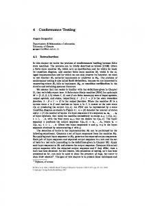
Fig. 1. Examples of specifications and implementations.
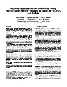
are lazy. In order not to overload the figures, we do not always draw inputcomplete automata. We assume that implementations ignore the missing inputs (this can be modeled by adding self-loop edges covering these inputs). Consider the specification Spec1 shown in Figure 1. Spec1 could be expressed in English as follows: “after the first a received, the system must output b no earlier than 2 and no later than 8 time units”. Implementations Impl1 and Impl2 conform to Spec1 . Impl1 produces b exactly 5 time units after reception of a. Impl2 produces b within 4 to 5 time units. Impl3 and Impl4 do not conform to Spec1 . Impl3 may produce a b after 1 time unit, which is too early. Impl4 fails to produce a b at all. Formally, out(Impl3 after a 1) = (0, 4] ∪ {b} and out(Impl4 after a 1) = (0, ∞), whereas out(Spec1 after a 1) = (0, 7]. Now consider specification Spec2 shown in Figure 2. This specification could be written down as: “if the first input is a then the system should output b within 10 time units; if the first input is c then the system should either output d within 5 time units or, failing to do that, output e within 7 time units”. The second branch of Spec2 is a typical specification of a timeout. If the “normal” result d does not appear for some time, the system itself should recognize the error and output an error message not much later. None of the four implementations of Figure 1 conform to Spec2 , as they do not react to input c (they ignore it). On the other hand, Impl5 and Impl6 of Figure 2 are conforming. It is worth noticing that Impl6 may output a b some time after receiving input f . The fact that input f does not appear in Spec2 does not affect the conformance of Impl6 . (In fact, Impl5 and Impl6 conform not only to Spec2 but also to Spec1 .) This example illustrates another property of tioco, namely, that an implementation is free to accept inputs not mentioned in the specification and behave as it wishes afterwards. This property is essential for capturing assumptions on the inputs (i.e., on the environment) in the specification. This is why we do not require specifications to be input-complete. Comparison: [28] define conformance as timed bisimulation (TB), which in their case reduces to timed trace equivalence (TTE), since determinism is assumed. [25] define conformance using a must/may preorder (MMP). None of Impl1 , Impl2
? e
a? � A c? x := 0� Ax := 0 � Ue τ - e A e� x = 5 e! x ≤ 10 b! d! x ≤ 5 x≤7
? e
? e
Spec2
? e
? e
a? � A c? x := 0� A x := 0
AU e
e��
x = 5 b!
d! 1 ≤ x ≤ 2
? e Impl5
? e
? e
a? � A c? � x := 0 x := 0� � f ? AAU � � e e b! x=5
��e
b!
? e ? e
e! x=6
? e
Impl6
Fig. 2. More examples of specifications and implementations.
conform to Spec1 w.r.t. TB, TTE or MMP. We believe that this is too strict.1 [23, 19] define conformance as timed trace inclusion (TTI). TTI is generally stricter than tioco: tioco allows an implementation to accept inputs not accepted by the specification, whereas TTI does not. When the specification is inputcomplete, tioco and TTI are equivalent. A deterministic (and fully observable) specification can be made input-complete without changing its conformance semantics by adding edges covering the missing inputs and leading to a “don’t care” location where all inputs and outputs are accepted. This transformation is not always possible for non-deterministic specifications. Moreover, if the transformation is performed, care must be taken to instruct the test generation algorithm not to explore the “don’t care” location, so that it does not generate useless tests. We opt for tioco, which avoids these complications in a simple way. For an extensive discussion of various untimed conformance relations, see [30].
4
Tests
A test (or test case) is an experiment performed on the implementation by an agent (the tester). There are different types of tests, depending on the capabilities of the tester to observe and react to events. Here, we consider two types of tests (the terminology is borrowed from [18]). Analog-clock tests can measure precisely the delay between two observed actions and can emit an input2 at any point in time. Digital-clock (or periodic-sampling) tests can only count how many “ticks” of a periodic clock have occurred between two actions and emit an input immediately after observing an action or tick. For simplicity, we assume that the tester and the implementation are started precisely at the same time. 1
2
It should be noted, however, that the issue does not arise in [28] because outputs are assumed to be urgent, thus, Spec1 cannot be expressed. We always use terms “input” and “output” to mean input/output of the implementation. Thus, we write “the test emits an input” rather than “emits an output”. We follow the same convention when drawing test automata. For example, the edge labeled a? in the TAIO of Figure 3 corresponds to the tester emitting a, upon execution of the test.
In practice, this can be achieved by having the tester issuing the start command to the implementation. It should be noted that we consider adaptive tests (following the terminology of [24]), where the action the tester takes depends on the observation history. Adaptive tests can be seen as trees representing the strategy of the tester in a game against the implementation. Due to restrictions in the specification model, which essentially remove non-determinism from the implementation strategy, some existing methods [28, 19] generate non-adaptive test sequences. 4.1
Analog-clock tests
An analog-clock test for a specification AS over Actτ is a total function T : RT(Act) → Actin ∪ {⊥, pass, fail}.
(7)
T (ρ) specifies the action the tester must take once it observes ρ. If T (ρ) = a ∈ Actin then the tester emits input a. If T (ρ) = ⊥ then the tester waits (lets time elapse). If T (ρ) ∈ {pass, fail} then the tester produces a verdict (and stops). To represent a valid test, T must satisfy a number of conditions: ∃t ∈ R . ∀ρ ∈ RT(Act) . time(ρ) > t ⇒ T (ρ) ∈ {pass, fail} ∀ρ ∈ RT(Act) . T (ρ) ∈ {pass, fail} ⇒ ∀ρ0 ∈ RT(Act) . T (ρ · ρ0 ) = T (ρ)
(8) (9)
Condition (8) states that the test reaches a verdict in bounded time t (called the completion time of the test). Condition (9) is a “suffix-closure” property ensuring that the test does not recall a verdict. We also need to ensure that the test does not block time, for instance, by emitting an infinite number of inputs in a bounded amount of time. This can be done by specifying certain conditions on the LTS defined by T . The states of this LTS are sequences ρ ∈ RT(Act). a The initial state is �. For every a ∈ Actout there is a transition ρ → ρ · a. There t is also a transition ρ → ρ · t for every t ∈ R, provided ∀t0 ≤ t.T (ρ) = ⊥. If b
T (ρ) = b ∈ Actin then there is a transition ρ → ρ · b. As a convention, all states ρ such that T (ρ) = pass are “collapsed” into a single sink state pass, and similarly with fail. We require that states of this LTS are non-blocking as in Condition (1), unless pass or fail is reached.
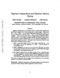
b! - pass 2≤y≤8 - e a? - e b! - fail y := 0 y8
T (�) T (a?) T (a? t) T (a? t) T (a? t b!) T (a? t b!)
= = = = = =
a? ⊥ ⊥, fail, fail, pass,
∀t ≤ 8 ∀t > 8 ∀t < 2 ∀t ∈ [2, 8]
Fig. 3. Analog-clock test represented as a TAIO or a function.
Analog-clock tests can sometimes be represented as TAIO.3 For example, the test defined in the right part of Figure 3 can be equivalently represented by the TAIO shown in the left part. Function T is partially defined in the figure. The remaining cases are covered by the suffix-closure property of pass/fail − Condition (9). For instance, T (a? 9 b!) = fail, because T (a? 9) = fail. Execution of the test T on the implementation AI can be defined as the parallel composition of the LTSs defined by T and AI , with the usual synchronization rules for transitions carrying the same label. We will denote the product LTS by AI kT . The execution of the test reaches a pass/fail verdict after bounded time. However, since the implementation can be non-deterministic or non-observable, the verdict need not be the same in all experiments (i.e., runs of the product). To declare that the implementation passes the test, we require that all possible experiments lead to a pass verdict. This implies that in order to gain confidence in pass verdicts, the same test must be executed multiple times, unless the implementation is known to be deterministic. Formally, we say that AI passes the test, denoted AI passes T , if state fail is not reachable in the product AI kT . We say that an implementation passes (resp. fails) a set of tests (or test suite) T if it passes all tests (resp. fails at least one test) in T . We say that T is sound with respect to AS if ∀AI . AI tioco AS ⇒ AI passes T . We say that T is complete with respect to AS if ∀AI . AI passes T ⇒ AI tioco AS . Soundness is a minimal correctness requirement. Is is rather weak, since many tests can be sound and useless (by always announcing pass). Completeness, on the other hand, is usually impossible to achieve with a finite test suite (see Section 5.3). We are thus motivated to define another notion. We say that a test T is strict with respect to AS if ∀AI . AI passes T ⇒ AI kT tioco AS . What the above definition says is that a strict test must not announce pass when the implementation has behaved in a non-conforming manner during the execution of the test. In the untimed setting, a similar notion of lax tests is proposed in [22]. The test shown in Figure 3 is sound and strict w.r.t. Spec1 of Figure 1. Changing the fail state of the test into pass would yield a test which is still sound, but no longer strict. 4.2
Digital-clock tests
Consider a specification AS over Actτ and let tick be a new output action, not in Actτ . A digital-clock test (or periodic sampling test) for AS is a total function D : (Act ∪ {tick})∗ → Actin ∪ {⊥, pass, fail}.
(10)
The digital-clock test can observe all input and output actions, plus the action tick which is assumed to be the output of the tester’s digital clock. We assume 3
But not always: the test which moves to pass once it observes a sequence of a’s such that the time distance between two a’s is 1 cannot be captured by a timed automaton with a bounded number of clocks. This is related to the fact that timed automata are not determinizable whereas a test is by definition deterministic.
that the initial phase of the clock is 0 and its period is 1. We further assume that the clock is never reset, and that ticks have priority over other observable actions (i.e., if tick and a occur at the same time, tick will be always observed before a). With these assumptions, if action a is observed after the i-th and before the (i + 1)-st tick, then the tester knows that a occurred at some time in the interval [n, n + 1). Validity conditions similar to those for analog-clock apply to digital-clock tests as well. Due to lack of space, we omit the formal definitions. A digital-clock test D defines a LTS with states in (Act ∪ {tick})∗ and labels in Act ∪ {tick} ∪ R. Given state π, if D(π) 6∈ Actin then π has a self-loop transition labeled with t, for all t ∈ R. The reason such transitions are missing from states such that D(π) = a ∈ Actin is that we assume that the digital-clock test emits a immediately after the last event in π is observed. Execution of a digital-clock test is defined by forming the parallel product of three LTSs, namely, the ones of tick! the test D, the implementation AI , and the Tick automax = 1 C eager ton shown to the left. Tick implicitly synchronizes with C -CW e x := 0 AI through time. Tick explicitly synchronizes with D on transitions labeled tick. The parallel product is built so Tick automaton. that tick transitions have priority over other observable tick transitions. Thus, if s is a state of the product and s →, then s has no other outgoing transition. The definition of passes for digital-clock tests is similar to the one for analog-clock tests, with AI kT being replaced by AI kTickkD. The definitions of soundness, completeness and strictness also carry over in the natural way.
5
Test generation
We adapt the untimed test generation algorithm of [29]. Roughly speaking, the algorithm ? c? �ai ! - Sl 0 builds a test in the form of a tree. A node in fail � · · · Sl aj ! � A the tree is a set of states S of the specification bi ! � � · · · AU bj ! and represents the “knowledge” of the tester at Sl Sl i j the current test state. The algorithm extends the test by adding successors to a leaf node, as Generic test-generation scheme. illustrated in the figure to the left. For all illegal outputs ai (outputs which cannot occur from any state in S) the test leads to fail. For each legal output bi , the test proceeds to node Si , which is the set of states the specification can be in after emitting bi (and possibly performing unobservable actions). If there exists an input c which can be accepted by the specification at some state in S, then the test may decide to emit this input (dashed arrow from S to S 0 ). At any node, the algorithm may decide to stop the test and label this node as pass. Two features of the above algorithm are worth noting. First, the algorithm is only partially specified. Indeed, a number of decisions need to be made at each
node: (1) whether to stop the test or continue, (2) whether to wait or emit an input if possible, (3) which input, in case there are many possible inputs. Some of these choices can be made according to user-defined parameters, such as the desired depth of the test. They can also be made randomly or systematically using some book-keeping, in order to generate a test suite, rather than a single test. We discuss this option in more detail in Section 5.3. The second feature of the algorithm is that it implicitly determinizes the specification automaton. Indeed, building Si , Sj and so on corresponds to a classical subset construction. The latter can be performed either off-line, that is, before the test generation, or on-line, that is, during the test generation or even during the test execution. Test generation during test execution has been termed on-the-fly and is supported by the tool Torx [3].
5.1
Generating analog-clock tests
Analog-clock tests cannot be represented as a finite tree, because there is an apriori infinite set of possible observable delays at a given node. To remedy this, we use the idea of [31]. We represent an analog-clock test as an algorithm. The latter essentially performs subset construction on the specification automaton, during the execution of the test. Thus, our analog-clock testing method can be classified as on-the-fly. More precisely, the test will maintain a set of states S of the specification TAIO, AS . S will be updated every time an action is observed or some time delay elapses. Since the time delay is not known a-priori, it must be an input to the update function. We define the following operators: a
dsucc(S, a) = {s0 | ∃s ∈ S . s → s0 } 0
(11) ρ
0
tsucc(S, t) = {s | ∃s ∈ S . ∃ρ ∈ RT({τ }) . time(ρ) = t ∧ s → s }
(12)
where a ∈ Act and t ∈ R. dsucc(S, a) contains all states which can be reached by some state in S performing action a. tsucc(S, t) contains all states which can be reached by some state in S via a sequence ρ which contains no observable actions and takes exactly t time units. The two operators can be implemented using standard data structures for symbolic representation of the state space and simple modifications of reachability algorithms for timed automata [31]. S The test operates as follows. It starts at state S0 = tsucc({sA 0 }, 0). Given current state S, if output a is received t time units after entering S, then S is updated to dsucc(tsucc(S, t), a). If no event is received until, say, 10 time units later, then the test can update its state to tsucc(S, 10). If ever the set S becomes empty, the test announces fail. At any point, for an input b, if dsucc(S, b) 6= ∅, the test may decide to emit b and update its state accordingly. At any point, the test may decide to stop, announcing pass. It can be shown that the test defined above is both sound and strict.
5.2
Generating digital-clock (periodic-sampling) tests
Since its set of observable events is finite (Act∪{tick}), a digital-clock test can be represented as a finite tree. In this case, we can decide whether to generate tests on-the-fly or off-line. This is a matter of a space/time trade-off. The on-the-fly method does not require space to store the generated tests. On the other hand, a test computed on-the-fly has a longer reaction time than a test which has been computed off-line. Independently of which option we choose, we proceed as follows. We first form the product A0S = AS kTick. We then define the following operator on A0S : ρ
usucc(S) = {s0 | ∃s ∈ S . ∃ρ ∈ RT({τ }) . s → s0 }.
(13)
usucc(S) contains all states which can be reached by some state in S via a sequence ρ which contains no observable actions. Notice that, by construction of A0S , the duration of ρ is bounded: since tick is observable and has to occur after at most 1 time unit, time(ρ) ≤ 1. b!
- ea? - etick - etick - etick - etick - etick - etick - etick - etick - etick b! b! - pass 2≤i≤8 - e a? - e b! - fail i := 0
�C i≤1 6
C tick tick i = 8 i≤7 i := i + 1
?
fail - pass
b!
- pass
- e a? - e2 tick- e 7 tick - fail b!
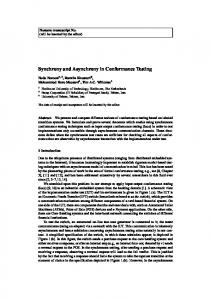
Fig. 4. A digital-clock test (top) and two alternative representations (bottom).
Finally, we apply the generic test-generation scheme presented above. The S root of the test tree is defined to be S0 = {sA 0 }. Successors of a node S are a computed as follows. For each a ∈ Actout ∪ {tick}, there is an edge S → S 0 with a S 0 = dsucc(usucc(S), a), provided S 0 6= ∅, otherwise there is an edge S → fail. If there exists b ∈ Actin such that S 00 = dsucc(tsucc(S, 0), b) 6= ∅, then the test b
generation algorithm may decide to emit b at S, adding an edge S → S 00 . Notice the asymmetry in the ways S 0 and S 00 are computed. The reason is that the tester is assumed to emit an input b immediately upon entering S. Thus, S 00 should only contain the immediate successors of S by b. The tests generated in this way are guaranteed to be sound. However, they are not strict in general. This is expected, since the tester cannot distinguish
between outputs being produced exactly at time 1 or, say, at time 1.5. A sound (but not strict) digital-clock test for Spec1 of Figure 1 is shown in the top of Figure 4. Reducing the size of digital-clock tests: Digital-clock tests can sometimes grow large because they contain a number of “chains” of ticks. On the other hand, standard test description languages such as TTCN [21] permit the use of variables and richer data structures. We would like to use such features to make the representation of digital-clock tests more “compact”. For example, the test shown in the top of Figure 4 can be equivalently represented as the automaton with counter i, shown in the bottom-left of the figure. Reducing the size of test representations is a non-trivial problem in general, related to compression and algorithmic complexity theory. In our context, we only use a heuristic which attempts to eliminate tick chains as much as possible. To this purpose, we generalize the labels of the digital-clock test to labels of the form k tick, where k is a positive integer constant. A transition labeled with k tick is taken when the k-th tick is received, counting from the time the source node is entered. Naturally, tick is equivalent to 1 tick. Now, consider two nodes tick S and S 0 such that: (1) S → S 0 , (2) for all a ∈ Act, the successors of S and S 0 k tick
are identical, (3) S 0 → S 00 . In this case, we remove node S 0 (and corresponding (k+1) tick
edges) and add the edge S → S 00 . We repeat the process until no more nodes can be removed. The result of applying this heuristic to the test in the top of Figure 4 is shown in the bottom-right of the figure. 5.3
Coverage
It is generally impossible to generate a finite test suite which is complete, in particular when the specification has loops, which define an infinite set of possible behaviors. This is because implementations can have an arbitrary number of states, while a finite test suite can only explore a bounded number of states. But an implementation could be conforming up to a certain point and not conforming afterwards. To remedy this fact, test generation methods usually make a compromise: instead of generating a complete test suite, generate a test suite which covers the specification.4 Different coverage criteria have been proposed for untimed systems, such as state coverage (every state of the specification must be “explored” by at least one test), transition coverage (every transition must be explored), and so on. A survey of coverage criteria and their relationships, in the context of software testing, can be found in [33]. In the case of timed automata the state space is infinite, thus, existing methods attempt to cover: either finite abstractions of the state space, e.g., the region graph in [28, 16], a time-abstracting partition graph in [25]; or the structural elements of the specification, e.g., [19] propose 4
Some methods [28, 12] generate a suite which is complete w.r.t. a given upper bound on the number of states of the implementation.
techniques for edge, location, or definition-use pair coverage and [8] consider various criteria in the context of timed Petri nets. In the spirit of [19], we propose a heuristic for generating a digital-clock test suite covering the edges of the specification automaton. Notice that we cannot use the technique of [19], which is based on formulating coverage as a reachability problem. Indeed, this technique relies on the assumption that outputs in the specification are urgent and isolated, which results in tests being sequences, rather than trees. Our method aims at covering edges labeled with an input action. Then, edges labeled with outputs will also be covered, since a test must be able to accept a any output at any state. Let T be a test suite and S → S 0 be an edge in some test of T , with a ∈ Actin . If e is an edge of AS labeled with a and enabled at some state in S, then we say that e is covered by T . We say that T covers AS if all input edges of AS are covered by T . Then, the test generation algorithm can stop once it has generated a test suite covering AS .
6
Tool and case study
We have built a prototype test-generation tool, called TTG, on top of the IF environment [7]. The IF modeling language allows to specify systems consisting of many processes communicating through message passing or shared variables and includes features such as hierarchy, priorities, dynamic creation and complex data types. The IF tool-suite includes a simulator, a model checker and a connection to the untimed test generator TGV [17]. TTG is implemented independently from TGV. It is written in C++ and uses the basic libraries of IF for parsing and symbolic reachability of timed automata with deadlines. TTG takes as main input the specification automaton, written in IF language, and can generate two types of tests: (1) analog-clock tests under the assumption that the implementation is discrete-time and has a time step of 1; (2) digital-clock tests with respect to a given Tick automaton. By modifying the Tick automaton, the user can implement different sampling rates, model jitter in the sampling period, and so on. TTG can be executed in an interactive mode, where the user guides the test generation by resolving decision points. TTG can also be asked to generate a single test randomly or the exhaustive test suite, up to a user-defined depth. The depth of a test is the longest path from the initial state to a pass or fail state. The tests are output in IF language. We have applied TTG to a small case study, which is a modification of the light switch example presented in [19]. The (modified) specification is shown in Figure 5. It models a lighting device, consisting of two modules: the “Button” module which handles the user interface through a touch-sensitive pad and the “Lamp” module which lights the lamp to intensity levels “dim” or “bright”, or turns the light off. The user interface logic is as follows: a “single” touch means “one level higher”, whereas a “double” touch (two quick consecutive touches) means “one level lower”. It is assumed that higher and lower is modulo three, thus, a single touch while the light is bright turns it off.
Lamp
Button x=D eager single! touch -
d? *BM Q single? � � � � QQy := 0 single � � B Q d� double? sd � B off! Q 6 Bd d� dim! single? I @ bright! m≤y≤M double? @ delayable 1 dXX @ � double �� XX@ � ? double? z X d dim! d� Y H � H � HH single? bright! H d �� � � off!
- d?touch?- d x := 0 K
touch? x = DA eager A
x < D double! A d �
� touch?
x