top-down or a bottom-up approach to design; ignoring the requirements for both abstraction and ... specialized to a particular application domain, or have focused on tools for engineering .... Along with name, the user describes the design.
Presented at the 7th Annual Industrial Engineering Research Conference, May 9-10, 1998, Banff, Alberta, Canada. CD-ROM (track 07 su 03)
Blending Top-Down and Bottom-Up Approaches in Conceptual Design Janis P. Terpenny Department of Industrial and Systems Engineering Virginia Polytechnic Institute and State University Blacksburg, Virginia 24061 Bartholomew O. Nnaji Department of Industrial Engineering University of Pittsburgh Pittsburgh, Pennsylvania 15260
Jan Helge Bøhn Department of Mechanical Engineering Virginia Polytechnic Institute and State University Blacksburg, Virginia 24061
Abstract In recent years, there has been significant attention given to improved methods and tools for engineering design. While advances for the latter stages of design have been impressive, this has not been the case for the early stages of design. In general, advances have provided for either a top-down or a bottom-up approach to design; ignoring the requirements for both abstraction and detail in a concurrently engineered development process. This paper describes an integrated conceptual modeling framework for a blended methodology. The utility and extensibility of this framework are considered in discussion and by way of examples. Keywords Conceptual Design, Functional Modeling, Concurrent Engineering, Configuration
1. Introduction Today, it has become apparent that the impacts, and therefore responsibilities, of designers go well beyond designing solutions to satisfy customer needs. Designers are challenged to complete their tasks quicker, at reduced costs, and push the edge of technology with innovation. In addition, designers are challenged to actively incorporate the objectives of company strategies in their decision processes. Consideration must be given to costs and cycle time of other life-cycle processes. Confirmed by estimates indicating 60-75% of life-cycle costs committed by the completion of conceptual design, there is a direct relationship between abstraction and detail. Abstractions (concepts, models) necessarily narrow the means available to configure feasible solutions. Further, improved efficiencies (cycle time and costs) and effectiveness (innovation and quality), simply cannot occur without sufficient detail for making informed decisions in early design. To date, advances for engineering design have predominantly focused on tasks that are well into the latter stages of development. Advances for early design still remain largely investigational, specialized to a particular application domain, or have focused on tools for engineering analysis. Rarely has there been consideration given to the requirements for functional abstraction (modeling) and the detailed information necessary for a concurrently engineered development process.
The inability of previous research to adequately address the early stages of conceptual design becomes evident when one considers the apparent dichotomy in current methodologies. In general, advances for early design have taken either a top-down or a bottom-up approach to design. In the top-down approach, characteristic of a systems engineering process, design is driven from functional requirements toward solution alternatives. While design solutions using this approach are likely to meet functional requirements, there is no guarantee that solutions are realizable in terms of physical manifestations. Frustrated with the time consuming and perhaps fruitless efforts of this approach, designers frequently abandon the effort seeking solutions in the combinatoric domain of detail. In contrast, using the bottom-up approach, characteristic of traditional engineering design practices, designs are built from known components (embodiments) in anticipation of satisfying functional requirements. In this scenario, physical realizability is guaranteed, but there is no immediate assurance that functional requirements are met. The bottom-up approach is known to be highly iterative. In the case of large or complex designs, the problem quickly leads to combinatorial explosion, inefficiency in the design process, and difficulties assessing the effectiveness and merits of design alternatives. This paper describes an integrated conceptual modeling framework that supports a blending of top-down and bottom-up approaches; one that provides for the frequent iterations between abstraction and detail that are needed in early design processes. A functional overview of the framework is provided first. This is followed with a top-level description of the associated architecture defining the modeling environment. The utility of the framework and its extensibility are then considered in discussion and by way of examples. Selected screens from a prototype system defined to illustrate and demonstrate the framework are included and support this discussion.
2. Integrated Conceptual Modeling Framework Engineering design is often characterized as an information-based process [1], [2]. From the earliest recognition of need, proceeding through to the completion of finalized design and documentation, information is gathered, manipulated, transformed, and generated. It is only logical, therefore, that any enabling technology which purports to support design processes must embrace the information needs of this process. Design processes require information for model representation, model analysis, solution synthesis, and evaluation. Information requirements can include model specific data as well as information sources external to the model. The integrated conceptual modeling framework uses three primary mechanisms to support the information requirements and processes of early design. Listed here these mechanisms include: a functional modeling environment, a components knowledge-base, and an integrated design domain. Each of these mechanisms is discussed in the sections that follow. An overview of the framework architecture is then provided. 2.1 Functional Modeling Environment The functional modeling environment serves as the focal point for the conceptual design process. The environment provides for concept modeling, knowledge collection/classification, and access to an integrated design domain. A building-block approach to modeling makes use of function objects. These objects are reflective of purpose (design intent), can be defined using the 'language' for a given application domain, and can be low-level or higher-level (decomposable)
2
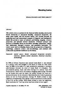
functions. Designers can create, save, and use these function building blocks within the modeling environment. Further, when placed within the context of a conceptual model, function objects can be connected through meaningful relationships (e.g., supports, cools, protects). In a manner similar to function object building blocks, relationships are created and maintained from selections within the modeling environment user interface. To summarize, the modeling environment permits the creation of conceptual models from a variety of levels of abstraction, enables knowledge capture, promotes reuse, and adds consistency to design practices. Further, the representation of concept models in terms of function objects provides a rich model for solution synthesis. 2.2 Components Knowledge-Base The components knowledge-base, referred to as the Engineering Model in the architectural description of the framework, provides an important link between the function objects of the conceptual model and the low-level rules and details required for solution synthesis. High-level function objects are decomposed during solution; terminating at the lowest level (component level). At this lowest level, component knowledge is characterized with attributes and engineering rules for decision processes. Rules may, for example, aid sizing, selection, material specification, or enforce company standards. 2.3 Integrated Design Domain As discussed previously, the impacts and requirements of early design processes are many. Conceptual designers naturally need to alternate between steps of reasoning in which detail is initially ignored to focus on high level functional abstractions (modeling), and steps in which the addition of detail is necessary for evaluation, design representation, and synthesis [3], [4]. Providing for these needs requires support for not only model creation, but also requires access to and/or the integration of many information resources. The integrated conceptual modeling framework provides for the interconnection of tools, analysis routines, and sources of data relevant to recording and making decisions in design. These sources are accessible from the functional modeling environment. In this manner, the modeling environment serves as a focal point for the conceptual design process. Figure 1 provides one possible definition of the integrated design domain. As shown, the modeling environment is central to the framework and is surrounded by a variety of knowledge, information, and analysis sources. In this particular instance, the domain has been setup to support the design of power conversion systems. Interconnections that support design include electrical schematics, bridge rating programs (analysis), simulation programs (evaluation), cost models, links to requirements as documented by marketing, and a variety of other sources. Clearly, developing all of the necessary relationships and connects with information and tools that may support the design process could be a challenging problem. At this point in time, the framework includes a windows-based user interface and the architectural constructs required for modeling, knowledge collection, and solution synthesis. Other applications and data existing beyond the immediate modeling environment are currently accessed by way of menu selection and/or window manipulation. Integration (rather than interface) will be considered in the future.
3
Graphical User
Marketing Requirements
Interface (GUI)
Schematic
Conceptual Modeling
CAD
Apprentice System System (CMS)
Conceptual Modeling System (CMS)
Other Analysis Modules
3D parametric models of devices, subassemblies, assemblies
Engineering Model
Conceptual Model
Expert Model
Presentation Model (Components Knowledge-Base)
(Functional Knowledge-Base)
Costs Model Bridge Rating Program Simulation Programs
Parts Database
Other Company Databases
Company Parts Database
Figure 1. Integrated design domain
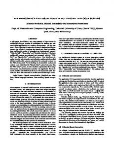
Figure 2. Top-level class category diagram
3. Framework Architecture Discussion of the architecture for the integrated conceptual design system will be limited in this presentation to the top-level class category diagram shown above in Figure 2. Seemingly uncomplex, each class category in the diagram is in reality a subset, or collection, of classes collaborating to provide a set of services. As shown, the categories are arranged in layers with several connections indicating “uses” relationships between categories. (Refer to Booch [5] or Jacobson [6] for details related to object-oriented analysis and design methods.) The sections that follow provide an overview of the class categories of Figure 2. In each case, an overview is provided describing the role, or service, that the category contributes to the overall system. Examples and discussion are then provided. 3.1 Graphical User Interface The graphical user interface (GUI) is at the highest level of abstraction in the top-level diagram. The role of the GUI is to provide the interface between the user and the conceptual modeling system. Microsoft Visual Basic [7] provided the application programming environment used to build over 20 interfaces for this application. 3.2 Conceptual Modeling System The conceptual modeling system, as shown in the class category diagram, is central to the architecture for integrated conceptual design. The purpose of this category in the diagram is to represent the functional partitioning of the system as well as its relationship to other systems. As implemented, the graphical user interface manages the interactions with class categories shown in “uses” relationships with the conceptual modeling system. Details of the participating components in the system are described in the class categories that follow. 3.3 Conceptual Model The conceptual model class category is concerned with the model that is current in the work area. The primary role of this category is to manage the conceptual model as it is constructed. The conceptual model also provides input for configuration processes and input for updates to the Expert Model (Functional Knowledge-Base).
4
3.4 Expert Model (Functional Knowledge-Base) The expert model provides two primary services to the conceptual modeling system. First, it provides the foundation for knowledge capture and reuse. Second, the expert model is integral in functional decomposition and solution synthesis procedures. 3.5 Engineering Model (Components Knowledge-Base) and Company Parts Database The engineering model category is concerned with the low-level functions (components) of design. The primary role of this class category is to support configuration processes of the system. The engineering model is used to specify components and interface with company databases in the part selection process. 3.6 Apprentice System and Presentation Model The Apprentice System is a commercially available knowledge-based engineering tool. As shown in the class category diagram, Apprentice System works directly with the conceptual modeling system. Its purpose is to provide the reasoning mechanism (inferencing) for solution synthesis (configuration). At this point, Apprentice handles the presentation of solution synthesis results to the user.
4. Examples and Discussion Figures 3 and 4 provide a limited sample of screens from the user interface for the integrated modeling environment. In its entirety, the prototyped system is comprised of over twenty (20) user screens. Collectively, these screens serve to define and implement the framework for integrated conceptual modeling. In Figure 3, the screen shown in full-view is illustrating a small portion of a design (one leg of a heatsink assembly within a power conversion system). The screen work-area provides the graphical palette for the building-block approach to conceptual modeling. Design objects (functions) are placed, connected, related, and constrained. As depicted in the screen that is partially hidden, the designer may locate function objects for modeling from function categories. Once a category has been selected, the designer is free to model with a specific solution type, or alternatively, may choose to use the generic function block (e.g., Semiconductor versus a particular type of semiconductor such as Thyristor).
Figure 3. Integrated modeling environment 5
Figure 4 illustrates the ease of maintaining system knowledge as well as model specific information within the system environment. The screen shown in full-view is the interface used to define a new function category to the system. Along with name, the user describes the design goal of the category, selects the relations that are associated with this category, and any attributes that are common to members of this group. As shown in the screen that is partially hidden, requirements specifications are readily defined for a given conceptual model. Further, attributes available in the system can be added or deleted to the specification list as needed. As one would expect, the requirements specification data provides the constraints required at the time of solution synthesis.
Figure 4. Maintaining domain knowledge and model data
5. Summary and Conclusions This paper has described an integrated design environment capable of enabling a blending of topdown and bottom-up approaches. Three primary mechanisms defining the integrated design environment were described including: functional modeling, a components knowledge-base, and an integrated design domain. An overview of the framework architecture has been provided along with examples serving to illustrate the use and utility of the framework. Although the examples included in this presentation have been a limited view of the overall framework, they provide the basis for the discussion of several key points. First, the framework provides the flexibility for blending top-down and bottom-up approaches to design. Designers are free to create concept models using high-level function objects, low-level function objects, or any combination thereof. This flexibility provides the choices and control over the design process that are often necessary in early stages. Few would question that it is good practice to reuse knowledge and quality solutions when available, yet one must also provide for novel discovery and invention. The framework provides for both of these capabilities with access to previously collected knowledge, the ability to capture and reuse new knowledge, and the ability to interface with other sources of information, knowledge, and/or tools during the design process.
6
Further, the framework is generalizable. Although shown in relation to the design of power conversion systems, the framework can be customized to a wide range of application domains. In each case, one would need to identify and capture the ‘language’ of the domain within the functions, categories, relations, and attributes defining the framework. For example, consider the utility of the framework and modeling approach for the design of manufacturing systems. Highlevel function objects used in modeling could generalize the concept model to reflect desired capabilities. Specific machines, tools, and processes would emerge with the solution synthesis of the model. Flexibility in modeling is possible when external conditions or preference dictates. Designers may create a concept model that is a combination of general building-blocks and building-blocks that are of a specific solution type. In addition to investigating the utility for other application domains, numerous other areas of future work exist for the framework, including: the concurrent design of product and life-cycle processes, mechanisms for the integration (rather than interface) of tools/data external to the system, spatial consideration of models and solutions, multiple model views, and generalized methods to assist knowledge and organization. In conclusion, the future for enabling technologies for engineering design remains a bright one; one with numerous possibilities. Technologies that are capable of blending top-down and bottom-up approaches in an integrated modeling environment represent one promising avenue for these future advancements.
Acknowledgements The authors gratefully acknowledge the sponsors of this work: General Electric Motors and Industrial Systems (GEMIS) located in Salem, Virginia and Virginia’s Center for Innovative Technology (Virginia’s CIT).
References 1. Colton, J.S. and Pun, R.C. “Information Frameworks for Conceptual Engineering Design,” Engineering with Computers, v 10, n1, 1994, pp. 22-32. 2. Ullman, D.G. “Issues Critical to the Development of Design History, Design Rationale and Design Intent Systems,” Proceedings - 6th International Conference on Design Theory and Methodology, 1994 ASME Design Technical Conferences, Minneapolis, Minnesota, Sept. 1994, DE v 68, pp. 249-258. 3. Paz-Soldan, J.P. and Rinderle, J.R. “The Alternate Use of Abstraction and Refinement in Conceptual Mechanical Design,” Proceedings of the ASME Winter Annual Meeting, ASME, San Francisco, CA, December 1989. 4. Szykman, S., and Cagan, J. “A Computational Framework to Support Design Abstraction,” Proceedings - 4th International Conference on Design Theory and Methodology, 1992 ASME Design Technical Conferences, Scottsdale, Arizona, Sept. 1992, DE v 42, pp. 27-39. 5. Jacobson, I. Object-Oriented Software Engineering, A Use Case Driven Approach. New York, Addison-Wesley, 1994. 6. Booch, Grady, Object-Oriented Analysis and Design with Applications, 2nd Edition, Benjamin/Cummings Publishing Company, Inc., Redwood City, California, 1994. 7. Microsoft Corporation. Microsoft Visual Basic Programming System for Windows, Version 4.0, United States, 1995.
7