In general, there is no specific range limit of the quality factor; a larger ..... [1] T. Fusio, âTwo-dimensional processing of TV signal,â NHK Tech. Res. Lab. J., vol.
IEEE TRANSACTIONS ON CIRCUITS AND SYSTEMS FOR VIDEO TECHNOLOGY, VOL. 8, NO. 3, JUNE 1998
345
Blocking Artifacts Reduction in Image Compression with Block Boundary Discontinuity Criterion Byeungwoo Jeon, Member, IEEE, and Jechang Jeong
Abstract— This paper proposes a novel blocking artifacts reduction method based on the notion that the blocking artifacts are caused by heavy accuracy loss of transform coefficients in the quantization process. We define the block boundary discontinuity measure as the sum of the squared differences of pixel values along the block boundary. The proposed method compensates for selected transform coefficients so that the resultant image has a minimum block boundary discontinuity. The proposed method does not require a particular transform domain where the compensation should take place; therefore, an appropriate transform domain can be selected at the user’s discretion. In the experiments, the scheme is applied to DCT-based compressed images to show its performance. Index Terms— Block boundary discontinuity, blocking artifacts, postprocessing, transform coding.
I. INTRODUCTION
T
RANSFORM coding has been widely used in many image compression applications. Recently, the discrete cosine transform (DCT) was adopted in the international standards of MPEG, JPEG, H.261, and others. The blockbased transform coding may cause blocking artifacts (or tiling effects) visible along block boundaries. They are caused by accuracy loss of transform coefficients in the process of independent quantization of each block. The artifacts are particularly annoying when transform coefficients are subjected to a coarse quantization. Since the quantization takes place in the transform domain, the effect of the quantization error is spread over all of the spatial locations within the block. The artifacts are noticeable particularly in the plain, or slowly varying parts of an image. Their reduction is very useful since noises with a geometric pattern with a strong vertical correlation are about ten times more perceptible than uncorrelated ones [1]. The blocking artifact caused by a block-based transform is an exemplar having geometric patterns. Subjective picture quality can be significantly improved by decreasing the artifacts with even a slight increase of random noise as a consequence. However, one should be careful not to destroy edges to which the human perception is sensitive. Therefore, the objective of the blocking artifact reduction is to maximally remove the extraneous noise introduced by the quantization process without sacrificing the Manuscript received July 15, 1996; revised March 15, 1997. This paper was recommended by Associate Editor R. Lancini. B. Jeon is with the School of Electrical and Computer Engineering, Sung Kyun Kwan University, Suwon, Korea. J. Jeong is with the Department of Electronic Communication Engineering, Hanyang University, 17 Hangdang Sungdong, Seoul, Korea. Publisher Item Identifier S 1051-8215(98)03978-0.
image sharpness. For this purpose, the characteristics of the human visual system (HVS) deserve to be thoroughly analyzed [2], [3]. A great deal of research has been carried out to reduce the artifacts. One approach is to allow blocks to overlap so that the adjacent ones can be dependent to some degree [4], [5]; the lapped orthogonal transform (LOT) [5] is particularly attractive in that it permits adjacent blocks to overlap without an additional increase in bit budget, i.e., it is critically sampled. Considering the fact that the artifacts are visible due to spatially high-frequency components produced by the block discontinuity, many kinds of low-pass filters were proposed [2], [4], [6], [7]. Jarske et al. [6] applied several filters to observe that the Gaussian low-pass filter with a highfrequency emphasis gave the best performance. With lowpass filtering images, special care should be taken not to smooth out image details. In this respect, Reeves and Lim 3 Gaussian low-pass filter only to those [4] applied the 3 pixels along block boundaries. Ramamurthi and Gersho [2] proposed a nonlinear space-variant filtering to reduce both so-called “staircase noise” and “grid effects”; based on the characteristics of the human visual system, a two-dimensional 3 3 FIR filter was employed to reduce the blocking artifacts in monotone areas, and a one-dimensional FIR filter was applied in the direction parallel to the edges so that the staircase noise in the areas containing edges could be reduced. Hsu and Chen [7], on the other hand, reported an adaptive scheme transforming the median filter progressively to the low pass filter as the filter approached the block boundaries. Recently, there have been approaches formulating the blocking artifacts reduction problem in the context of the regularized image recovery so as to utilize prior knowledge on the smoothness of the original image. Two similar schemes have been proposed: the projections onto convex sets (POCS) method [8] and the constrained least square method [8]–[10]. Yang et al. [8] used prior knowledge on the smoothness of the original image, and defined a new convex constraint set conveying the smoothness. The reconstructed image was obtained through iterative projections onto the convex sets. The convergence was reported fast, usually in fewer than ten iterations. In a similar context, Yang et al. [8] also proposed the constrained least square method which sought the reconstructed image by minimizing an objective function reflecting the smoothness property. By noting that the quantization error of the transform coefficients and the pixel differences over block boundaries should be bounded, Zakhor [9] (see also Reeves and Eddins [10]) proposed a solution minimizing
1051–8215/98$10.00 1998 IEEE
346
IEEE TRANSACTIONS ON CIRCUITS AND SYSTEMS FOR VIDEO TECHNOLOGY, VOL. 8, NO. 3, JUNE 1998
frequency-weighted energy of an image while maintaining fidelity to the known quantization constraints. On the other hand, Tien and Hang [11] proposed a method adjusting the quantized transform coefficients of a decoded image. It first decides whether the block is over edge(s) or in a monotone areas. In an edge area, the most similar quantization error pattern is sought by comparing the received quantized coefficients with the clusters of typical quantization patterns which are pre-defined through a training process. Representative quantization errors are preassociated with each cluster. The quantization errors corresponding to the most similar pattern are then added to the received ones. In a monotone area, the dc and the first-order horizontal and vertical DCT coefficients are adjusted to reduce the discontinuity over the block boundary. It is worthwhile to note the approaches to the error concealment problems in ATM network environments which Wang et al. [12] and Park et al. [13] reported. These approaches recover DCT coefficients lost during network transmission by maximally smoothing the transition of pixel values over block boundaries. Note that the blocking artifacts reduction can be similarly considered as an attempt to recover the accuracy loss of quantized transform coefficients. The only difference is that the latter has initial values of blocks, but the former does not. In this context, we propose a postprocessing approach which can achieve minimum discontinuity of pixel values over block boundaries by compensating the loss of a coefficient’s accuracy in the transform domain. To quantify blocking artifacts, the block discontinuity measure is defined as the sum of squared pixel differences over the four block boundaries. The proposed method finds the compensating transform coefficients whose inverse transform can minimize the block discontinuity when added to the dequantized received image. The proposed method can be taken in an arbitrary transform domain, not necessarily in the same one that its compression is based upon. This implies great flexibility in hardware implementation. For example, it can be easily implemented in the Walsh–Hadamard transform domain which is multiplication free. The proposed scheme is distinct from the Tien and Hang’s [11] in several points. First of all, Tien and Hang just modify the dc and first horizontal and vertical DCT coefficients in a rather heuristic way. The modified dc term is a simple weighted average over the center block and its eight neighbors. The gap-adjusted first horizontal (HAC) and vertical (VAC) coefficients are averages of adjacent horizontal and vertical DCT coefficients, respectively. This independent horizontal and vertical interpolation of DCT coefficients turns out to be suboptimal in the minimal block discontinuity sense, as will be explained in Section II. Furthermore, the proposed method can easily choose more than three compensating terms, contrary to [11]. As a matter of fact, it is one conclusion of this paper that there are unique solutions of up to 28 compensating terms when the criterion is minimizing the discontinuity of pixels along block boundaries. Although that many coefficients may be used in a very rare situation, this conclusion provides a theoretical limit of the number of compensating terms in the aforementioned error concealment approach [12], [13].
The rest of this paper is organized as follows. Section II describes the proposed method, and Section III derives the optimal compensation signal minimizing the discontinuity measure. Section IV discusses how the compensating transform coefficients can be selected. To demonstrate the performance of the proposed method in enhancing visual quality, experimental results with the JPEG and the MPEG-2 intracoded images are presented in Section V. Finally, Section VI concludes this paper. II. POSTPROCESSING WITH MINIMUM BLOCK BOUNDARY DISCONTINUITY Let us consider an image which has blocks, each of A pixel value at in size the th block, is denoted by where the blocks are numbered sequentially from 1 beginning at the top left to the bottom right in a raster-scan order. Each block of image, is transformed to where and are coordinate indexes, respectively, in the spatial and transform domains. In JPEG [14], the transformed DCT coefficient is quantized with a quantization step size which is generally determined by the coefficient location and color component being encoded. The quantization process is modeled by [15]
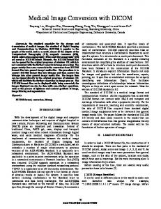
(1a) is a quantized value of with a quanwhere tization step size truncates the fractions off. The ’s, , , are specquantization step sizes ified in a JPEG-compressed file as a part of table specification. Assuming no other noise exists other than that by quantization, the dequantized value at a decoder is and the quantization error is The quantization error is bounded as (1b) Since the quantization process is in a transform domain, the quantization error affects pixel values over all of the spatial locations. Let us denote the decoded image by and its th block by The resultant quantization error in the spatial domain is defined as (1c) Fig. 1 shows how the accuracy loss in a transform domain affects the image look in the spatial domain. Note that the discontinuities along block boundaries in Fig. 1 are prolonged successively in the vertical and horizontal directions, thus producing a highly structured pattern of artifacts. The severe blocking artifacts present a tiling image look, and are perceptually extremely objectionable. To quantify the blocking effects of a given image the block discontinuity of the th block is defined by (2a) as
JEON AND JEONG: BLOCKING ARTIFACTS REDUCTION
347
Fig. 1. Blocking artifact due to quantization. Shown are the pixel values of line 436, columns 224–368 of the dequantized (QF = 4) and original Lena image (for details, see Section IV).
The block discontinuity of a decoded image obtained by
is then
(2c)
Fig. 2. Top, bottom, left, and right adjacent blocks. (The subscript number of blocks in a horizontal direction.)
P
In JPEG, the quantization step size is controlled for a desired compressed file size. One implementation [15] of this such that mechanism is to use the so-called quality factor is the
(3)
the sum of squared pixel differences over block boundaries.
(2a) The subscript is the number of blocks in a horizontal direction; therefore, and refer to pixels in the top and bottom blocks of the th block, respectively, as shown in Fig. 2. and refer to left and right adjacent Similarly, blocks. For the blocks along the image boundaries, the block boundary discontinuity accounts for only the available neighboring blocks. The total block discontinuity is (2b)
is a default quantization step size for DCT where As increases, the compression ratio coefficient at also increases. Fig. 3 shows an average block discontinuity of a decoded Lena image for different quantization levels (i.e., with various ’s). In general, there is no specific range limit of the quality achieves more compression, but worse factor; a larger image quality. Note that the uncompressed original image has some value of the block boundary discontinuity as in Fig. 3. We will investigate the postprocessing method of Fig. 4, in which a compensation signal is added to the dequantized image We define the compensation signal, which so that the resultant signal is to be added to (4) under has the minimum block boundary discontinuity the constraint in (1b). The compensation signal is estimated for each block. This is a constrained least square problem similar to [8]; however, the minimization will be performed in a transform domain. If one can estimate the quantization error ’s in (1c), then using would completely remove blocking artifacts. However, it is impossible to know the quantization error in a decoder; therefore, the best one can do is to add to the decoded image an which can minimize block discontinuity. appropriate
348
IEEE TRANSACTIONS ON CIRCUITS AND SYSTEMS FOR VIDEO TECHNOLOGY, VOL. 8, NO. 3, JUNE 1998
Fig. 3. Average blocking boundary discontinuity [(2c) is normalized by the number of block boundary pixels].
Let us define
and
as
(5a) and obtain cessed image and
Fig. 4. Postprocessing of dequantized image.
the th block discontinuity of a postproin terms of compensation signals ’s, :
(5b) The total block discontinuity of the postprocessed image
Fig. 5. Two subsets of blocks.
f1
sitesg and
f2
sitesg:
is (5c)
blocks are coupled together in (5c) since Note that all needs adjacent postprocessed blocks, i.e., the pixel and values of Instead of dealing with all of the blocks simultaneously in minimizing (5c), which is too complex to be practical by any means, we take an iterative approach by separating the blocks into two subsets as in Fig. 5 such that the minimization can be processed independently in each subset in an iterative way: (6)
The set refers to all sites and refers to all sites in Fig. 5. We call it the alternate optimization. In each step of the iteration, minimization is performed with only one set of sites, assuming that the reconstructed values are available for the other set (the values at the previous iteration are used instead of the postprocessed values). This iteration continues until there are negligible changes after the update. III. MINIMIZATION IN A TRANSFORM DOMAIN In our approach, the minimization of (6) takes place in a transform domain. For this purpose, the compensation signal is written in terms of transform coefficients. The transform coefficients are then estimated so that the discontinuity measure of (6) can be minimized. The transform need not necessarily
JEON AND JEONG: BLOCKING ARTIFACTS REDUCTION
349
be the same one the encoder uses, although the same transform is a natural choice in most cases. Consider a separable transform with a kernel function the normalized kernels in the and direction and For example, in the case are, respectively, of the DCT,
The same matrix operation is performed for the kernel function vector:
(8b) is the vector corresponding to Note which satisfies With that one can always find the selected transform coefficients, the compensation signal is written in a transform domain as (9)
where if and otherwise. The kernel function is represented in a raster-ordered vector as
Substituting this in (5b) results in the discontinuity (10a) where
where denotes Similarly, the transform coefficients of the compensation signal of the th block are written vector, denoted by : as an
(10b) where is the transform coefficient Now, the corresponding to the transform kernel compensation signal of the th block is represented by
(7)
Due to the low-pass characteristics of the human visual system and the nature of the blocking artifacts visibility, it is sufficient to use only a few coefficients, especially low-frequency components, for the purpose of compensation. To indicate explicitly the transform coefficients selected for matrix such compensation, we define a diagonal are zeros and the th diagonal that all off-diagonals of element is one if and only if the th transform coefficient of is selected to be compensated; all deselected the vector diagonals are zeros. transform coefficients are selected for Suppose that only vector which the compensation, and define the consists of only the selected ones. One can define an invertible matrix which, when multiplied by the column from the left, moves the selected coefficients to the matrix top portion of the column matrix so that it can satisfy the following relation:
(10c) Now, the unknown vector can be estimated by minimizing (6) using (10a) under the constraint in (1b). Since (10a) is a there should exist quadratic equation of the vector which minimizes (10a). Note that the matrix is symmetric; therefore, by setting to zero each first-order derivative of (10a) the optimum solution of with respect to the element of can be obtained by solving (11) Any compensation coefficient in not satisfying the constraint in (1b) is projected into the nearest value satisfying is invertible, then the unknown the constraint. Suppose transform coefficients vector is
(8a) (12a)
350
IEEE TRANSACTIONS ON CIRCUITS AND SYSTEMS FOR VIDEO TECHNOLOGY, VOL. 8, NO. 3, JUNE 1998
and the resulting minimum block discontinuity is where (12b) is independent of the actual pixel In (11), the matrix and the transform domain values, that is, once the matrix can be computed. Therefore, it are decided, the matrix (or its inverse, if it exists) can be precalculated in the step is the of designing the proposed method. The vector sum of the transformed pixel difference values over the block boundaries. It is possible to simplify (11) with transforms having properties (13) by dividing transform coefficients into the even and odd parts. Suppose a proper rearrangement is carried out for and the unknown the transform kernel vector so that compensation coefficient vector
will be very efficient from a hardware implementation point of view. It is important to remember that postprocessing with the solution of (12a) can be performed in an arbitrary transform domain. This property allows great flexibility in hardware implementation. The implication of formulating the problem in terms of four subequations is significant. Since the matrix inversion and multiplication can be performed for each of the submaand the compensation trices coefficients can be independently calculated, the computation requirement is greatly reduced. Following is the example of using four lower DCT coefficients for the compensation:
(15a) where the four unknown DCT coefficients can simply be computed using (14):
Note that ’s are scalars. The compensating DCT coefficients are calculated as
(15b)
(15c)
(The first index in refers to the (even) component, and the second index refers to the (odd) components.) From the orthogonality of the transform kernel functions, the computed as in (10b) can be shown block diagonal matrix Therefore, (11) with elements can be divided into four submatrix equations as (14) where, for
and
taking either
(even) or
(15d) (15e) is the th one-dimensional DCT coefficients of where as defined
(odd),
The DCT kernel function satisfies the condition in (13); however, the discrete Fourier transform (DFT) does not. Therefore, when the DFT is taken, (11) cannot be simplified into (14). It is noteworthy that the Walsh–Hadamard transform (WHT) in the sequency order satisfies the relation in (13) and is multiplication free. The proposed scheme based on WHT
It is noteworthy that, although adding a compensating signal in one direction decreases discontinuities in that direction, it may increase discontinuity in the other direction as well. Imagine an example which has a block boundary difference only in the vertical direction. Adding a compensating term to reduce the discontinuity in the vertical direction will produce artificial discontinuity in the horizontal direction. In the example above, the term in (15c) and in (15d) are controlling the tradeoff between reducing the discontinuity in the desired direction and the induced artificial discontinuity in the other direction. However, under the framework of Tien and Hang’s result [11], the artificial discontinuity is not controllable since the compensating coefficient does not have a term accounting for the discontinuity in the other direction. This is because Tien and Hang simply calculated the vertical and horizontal adjustment coefficients independently, only considering the
JEON AND JEONG: BLOCKING ARTIFACTS REDUCTION
351
Fig. 6. Minimization of block boundary discontinuity in the spatial domain.
corresponding directions. In this respect, the proposed method is more general than Tien and Hang’s. In addition, the dc component compensation in Tien and Hang’s is accomplished by substituting the dc value with the weighted average of dc coefficients over the center block and its eight neighbors with a weighting matrix [1 1 1; 1 13 1; 1 1 1], which is not necessarily optimal in the context of minimizing block discontinuity. Note that the dc compensation term in (15b) in a spatial domain corresponds to a simple average of pixel differences over the block boundaries. IV. TRANSFORM COEFFICIENTS SELECTION It is important to note that the existence of the matrix depends on how the compensation coefficients are selected. That is, depending on how coefficients are selected, the rank may not be the same as the number of selected of coefficients. Note that the maximum rank of matrix is even if all of the coefficients are selected for the compensation. This can be understood conceptually in the following way. To minimize the block discontinuity in a spatial domain, it suffices for the block boundary pixels to duplicate the corresponding pixel values of the adjacent blocks as in Fig. 6. In the case of corner pixels, a simple average of the pixel values of the two relevant blocks is used. This means that, no matter what values are used for the boundary pixels, the inner pixels can take arbitrary values without changing the discontinuity. It implies that, also in the transform domain, number of coefficients are unconstrained. Therefore, (11) with the matrix being the identity matrix coefficients are selected) is underdetermined (that is, all with a degree of freedom and the rank of the matrix is In the case of an 8 8 block, this means that one can decide only up to a maximum of 28 coefficients by minimizing the discontinuity measure. It provides a theoretical limit on the number of compensating terms of the error concealment problem in [12], [13]. To investigate the dependency of the rank of the matrix on the selection pattern the rank is computed as a new transform coefficient is sequentially included one by one in the order of a zig-zag scan as in Fig. 7(a). The computed rank is written in the corresponding location in Fig. 7(b). The rank of increases as a new transform coefficient is added until the component at is included. The coefficients corresponding to the lower 6 6
(a)
(b) Fig. 7. Rank (QH ) in zig-zag scan order. (a) Zig-zag scan order. (b) Rank increase of matrix QH :
Fig. 8. Quantization step size.
Fig. 9. Mean-squared quantization error distribution of 8 cients in zig-zag scan order (Lena image).
2 8 DCT coeffi-
submatrix were found to be redundant given the other 28 coefficients. In general, the matrix has the maximum rank if any two rows and two columns of transform coefficients are selected. In practical applications, however, the number of coefficients is often limited by the complexity of
352
IEEE TRANSACTIONS ON CIRCUITS AND SYSTEMS FOR VIDEO TECHNOLOGY, VOL. 8, NO. 3, JUNE 1998
Fig. 10. Image profile of postprocessed Lena image at line 436, QF = 4: (The proposed method uses DCT coefficients at (0,0), (1,0), (0,1), and 3 averaging filter almost coincided with that of 3 3 Gaussian filter for the selected (1,1) with � = 0:5—see Table II. The output of the 3 portion of image, thus invisible.)
2
2
a different would not be very desirable due to hardware complexity, and a certain fixed pattern is most likely to be used. Since the blocking artifacts are seriously annoying in the plain part of the image where there are not many highfrequency components, only a few low-frequency components and are expected to be most (for example, effective. Fig. 11.
Induced artifact due to compensation.
V. EXPERIMENTS postprocessing, and it is very likely to use only a set of lower frequency components of the transform coefficients. When only a few coefficients are selected for compensation, they should be selected considering not only the invertibility of the , but also the effectiveness in reducing the blocking matrix artifacts. The effectiveness of the compensating coefficients surely depends on the actual pattern of block discontinuity. To select coefficients which are more effective in reducing which can minimize (12b) discontinuity, a selection matrix (equivalently, maximizing should be chosen. For an example, suppose there are two choices of coefficient selection as specified by and Then the and are compared to choose the corresponding selection matrix which gives a larger If the block discontinuity in (12b) can be easily calculated since and are scalars. Among different choices of compensating transform coefficients, the one giving a minimum of (12b) is transform coefficients selected. However, choosing optimal in general is impossibly complex. One suboptimal approach is to decide coefficients successively one by one; that is, after choosing the best coefficient maximizing where has only one nonzero diagonal element, select the other best coefficient given the previous selection, and so on. Note that the quantity depends on the block boundary values, which are different from block to block. Therefore, the for each block is, in general, nonidentical optimal matrix for different blocks. In a real application, however, selecting
AND
DISCUSSION
To demonstrate the performance of the proposed method, the Lena and Susie images were compressed using a JPEG [15] and MPEG-2 intrapicture [16], respectively. In JPEG coding, the quantization equation in (1a) was used with the default quantization table in Fig. 8. The block size was 8 8. In JPEG coding, the quality factor in (3) was set to 4, which produced a compression ratio of 33.66, resulting in 0.24 bits/pixel. In the MPEG-2 intracoding of the Susie image (16th frame), the compression ratio was 48.61 (0.16 bits/pixel). The compensation was performed in the DCT domain. Before deciding on the DCT coefficients to be used for the proposed method, spectral distribution of the mean-squared error of (1b) on the DCT domain was checked with different quality factors as in Fig. 9. The DCT coefficients in the horizontal axis were in the order of a zig-zag scan. The error was observed to be dominated by the low-frequency components. Although one can uniquely identify a maximum of 28 DCT coefficients by the proposed artifacts reduction method, we have considered only up to four since the perceplower DCT coefficients tual deterioration of blocking artifacts is mostly caused by the heavy accuracy loss of lower frequency components. With the DCT transform with four compensation coefficients, solving (11) results in the compensating coefficients in (15a)–(15e). To make a comparison with other blocking artifacts reduction methods, the 3 3 Gaussian low-pass filter was applied
JEON AND JEONG: BLOCKING ARTIFACTS REDUCTION
353
TABLE I BLOCK BOUNDARY DISCONTINUITY
BLOCK BOUNDARY DISCONTINUITY
TABLE II AND PSNR
to the pixels along block boundaries, as was proposed by Reeves and Lim [4], however, it still left perceptible block discontinuities. To see the possible degree of blocking artifacts 3 averaging filter with reduction with linear filtering, a 3 1/9[1 1 1; 1 1 1; 1 1 1], which was an extreme case of low-pass filtering, was applied to all pixels. The artifacts were considerably reduced. However, there remained blocking artifacts still noticeable, not to mention severe image blurring. From this test, it was observed that there was a certain limit in reducing blocking artifacts by using linear filters. To understand why the linear filtering approaches still leave noticeable blocking artifacts, an image profile is drawn as in 3 averaging filter is Fig. 10 (the image profile of the 3
OF
AND
PSNR
POSTPROCESSED LENA IMAGE
invisible since its output almost coincides with that of the 3 3 Gaussian filter). The filtering approaches were successful in reducing the jumps in pixel values across the block boundary; that is, the transitions over block boundaries became less abrupt. However, the gaps over boundaries were still too large to be imperceptible, and new discontinuities (tips in the image profile in Fig. 10) caused the tiling effects to be newly perceivable. To distribute the gaps among pixels, a filter with a larger support can be used, but this would blur the image considerably. On the contrary, the proposed method adds to the dequantized signal the compensation term which is the
354
IEEE TRANSACTIONS ON CIRCUITS AND SYSTEMS FOR VIDEO TECHNOLOGY, VOL. 8, NO. 3, JUNE 1998
TABLE III BLOCK BOUNDARY DISCONTINUITY AND PSNR
weighted sum of smooth functions such as DCT kernels which have values intrinsically inside the blocks. Now, the gaps along block boundaries are smoothly scattered inside blocks, and become imperceptible. Table I shows the block boundary discontinuity of (2a) normalized by the number of boundary pixels. In the experiment, two different optimization methods were tested to see their effects. One is to process two subsets of blocks alternately as described in Section II (denoted by Alternate Optimization in Table II), and the other is to process all of the blocks sequentially in the raster scan order (denoted by Raster Scan Optimization in Table II). The alternate optimization needs two passes of image data access per one iteration. In the experiment, only one iteration was performed since the postprocessing is less appealing if it needs much computation. Under the raster scan optimization, the pixel difference over and are substituted simply by the block boundary the difference of the dequantized values to further simplify the processing. In this case, the discontinuity can be overcompensated, thus producing a new discontinuity as in Fig. 11 since block discontinuity is compensated twice independently by two blocks sharing the block boundary. To solve this, Tien and Hang [11] scaled the compensation value by half. In this paper, we introduce a weighting factor which is multiplied to the estimated compensation coefficients
OF
POSTPROCESSED SUSIE IMAGE
to control the degree of compensation. Under the alternate optimization, the weighting factor closer to one is expected to attain minimum discontinuity since alternate optimization and sets assumes that the neighboring blocks over are already compensated when a block is being compensated. However, in the raster scan optimization, a weighting factor value near 0.5 is expected to be appropriate since two independent compensations by two blocks are carried out. Tables II and III list the measured block discontinuity and PSNR of the postprocessed Lena and Susie images, respectively. The block discontinuity was considerably reduced after the postprocessing, and the PSNR was found, in general, slightly lowered. However, the visual look was significantly enhanced after the proposed postprocessing. It is a well-known experimental observation that the PSNR measure does not necessarily predict the visual quality [3], [8] precisely. The pixels near edges were found to lower the PSNR values. In the experiment, it was found that a compensation signal having the firstorder horizontal and vertical DCT coefficients attained very good performance with a relatively small computational burden. Including second-order horizontal and vertical terms was less successful in improving visual quality. This was because the symmetric nature of the second-order terms did not match well with slowly increasing or decreasing image values in a plain area where the blocking artifacts were most perceivable.
JEON AND JEONG: BLOCKING ARTIFACTS REDUCTION
355
(a)
(b)
(c)
(d)
2
2
256 portion of the Lena image is displayed). (a) Before postprocessing. (b) 3 3 Gaussian filter only Fig. 12. Comparison of postprocessing (only 256 3 averaging filter to all pixels. (d) Proposed method. ( a00 ; a10 ; a01 with � = 0:5; alternate optimization). to the boundary pixels. (c) 3
2
As seen in Tables II and III, there was a slight difference between the two optimization methods. As expected, a weighting produced the minimum block discontinuity factor attained under the alternate optimization, and its minimum discontinuity under the raster-scan optimization. The alternate optimization generally produced a slightly larger block discontinuity than the other, but it gave a slightly higher PSNR. This trend was more conspicuous when the weighting factor was large. This is somewhat expected since, as the weighting factor becomes larger, it is more likely that the induced artifacts occur as shown in Fig. 11. For visual assessment, the blocky reconstructed images before and after the postprocessing are shown in Fig. 12 (Lena)
f
g
and Fig. 13 (Susie). For a closer visual comparison, presented 256 portion which could most clearly is the selected 256 show the performance of the proposed method. The images in Figs. 12(d), 13(d) used the compensation coefficient dc, the first horizontal, and vertical DCT coefficients with a weighting factor of 0.5. The discontinuity was alternately optimized. gave good Visually, small weighting factors of results. Before the postprocessing, there was an unacceptable degree of blocking artifacts, especially in the face and shoulder 3 Gaussian filtering leaving portions. Contrary to the 3 many artifacts, the proposed method significantly reduced the 3 averaging artifacts. Note the blurring caused by the 3 filter.
356
IEEE TRANSACTIONS ON CIRCUITS AND SYSTEMS FOR VIDEO TECHNOLOGY, VOL. 8, NO. 3, JUNE 1998
(a)
(b)
(c)
(d)
2
2
Fig. 13. Comparison of postprocessing (only 256 256 portion of the MPEG-2 intracoded Susie image is displayed). (a) Before postprocessing. (b) 3 3 Gaussian filter only to the boundary pixels. (c) 3 3 averaging filter to all pixels. (d) Proposed method ( a00 ; a10 ; a01 with � = 0:5; alternate optimization).
2
One drawback of the proposed method is in the edge areas. In Fig. 13(d), the artifacts near the left chin and telephone edges are distracting. It is noteworthy that one can selectively apply the proposed method based on the image content such as edge/smooth areas. In smooth areas, the degree of compensation can be increased. This can be achieved by using In the area near the larger values of the weighting factor edges, the directional low-pass filtering or some of the edgeenhancing filters can be considered, as suggested in [2]. In those images with severe blocking artifacts, the edges are most likely to be corrupted also; therefore, the edge-enhancing operation would be very desirable. It is also conceivable to use different weighting factors for different frequency components;
f
g
one immediate possibility may be to relate the weighting factor to the human visual sensitivity. This special treatment of the edge area and its detail is currently under investigation. VI. CONCLUSION We have proposed a transform-domain blocking artifacts reduction method based on minimizing the block boundary discontinuity. The proposed method estimates a set of compensating transform coefficients (especially low-frequency components) in the transform domain of the user’s selection. The compensating signal is added to the received blocky image so that the resulting postprocessed image attains minimum block boundary discontinuity.
JEON AND JEONG: BLOCKING ARTIFACTS REDUCTION
The proposed method is very flexible since it does not require a specific transform in which the postprocessing should take place. From a computational viewpoint, the proposed method is simple as well since the solution equation can be decomposed into four subequations when the selected transform satisfies the symmetric and antisymmetric conditions. It block transform, there are is proven also that, for an transform coefficients due unique solutions of up to to the boundary constraints. With images compressed using DCT, the performance was shown to be very effective in enhancing visual quality without sacrificing image sharpness. The proposed method can be easily extended to be selectively applied depending on image activity. REFERENCES [1] T. Fusio, “Two-dimensional processing of TV signal,” NHK Tech. Res. Lab. J., vol. 25, pp. 157–180, Mar. 1973. [2] B. Ramamurthi and A. Gersho, “Nonlinear space-variant post processing of block coded image,” IEEE Trans. Acoust., Speech, Signal Processing, vol. ASSP-34, pp. 1258–1268, Oct. 1986. [3] W. K. Pratt, Digital Image Processing. New York: Wiley, 1978. [4] H. C. Reeves, III and J. S. Lim, “Reduction of blocking effects in image coding,” J. Opt. Eng., vol. 23, pp. 34–37, Jan./Feb. 1984. [5] H. S. Malvar and D. H. Staelin, “The LOT: Transform coding without blocking effects,” IEEE Trans. Acoust., Speech, Signal Processing, vol. 37, pp. 553–559, Apr. 1989. [6] T. Jarske, P. Haavisto, and I. Defe’e, “Post-filtering methods for reducing blocking effects from coded images,” IEEE Trans. Consumer Electron., pp. 521–526, Aug. 1994. [7] Y.-F. Hsu and Y.-C. Chen, “A new adaptive separable median filter for removing blocking effects” IEEE Trans. Consumer Electron., vol. 39, pp. 510–513, Aug. 1993. [8] Y. Yang, N. P. Galatsanos, and A. K. Katsaggelos, “Regularized reconstruction to reduce blocking artifacts of block discrete cosine transform compressed images,” IEEE Trans. Circuits Syst. Video Technol., vol. 3, pp. 421–432, Dec. 1993. [9] A. Zakhor, “Iterative procedures for reduction of blocking effects in transform image coding,” IEEE Trans. Circuits Syst. Video Technol., vol. 2, pp. 91–95, Mar. 1992. [10] S. J. Reeves and S. L. Eddins, “Comments on iterative procedures for reduction of blocking effects in transform image coding,” IEEE Trans. Circuits Syst. Video Technol., vol. 3, pp. 439–440, Dec. 1993. [11] C.-N. Tien and H.-M. Hang, “Transform-domain post processing of DCT-coded images,” Proc. SPIE, Visual Commun. Image Processing, vol. 2094, pp. 1627–1638, Nov. 1993. [12] Y. Wang, Q.-F. Zhu, and L. Shaw, “Maximally smooth image recovery in transform coding,” IEEE Trans. Commun., vol. 41, pp. 1544–1551, Oct. 1993.
357
[13] J. W. Park, D. S. Kim, and S. U. Lee, “On the error concealment techniques for DCT based image coding,” in Proc. ICASSP, vol. 3, 1994, pp. 293–296. [14] G. K Wallace, “The JPEG still picture compression standard,” Commun. ACM, Apr. 1991. [15] Portable Research Video Group’s (PVRG) PVRG-JPEG Software Codec V1.2, ftp://havefun.stanford.edu:/pub/jpeg/JPEGv1.2.tar.Z. [16] ISO/IEC, “MPEG-2 test model 5,” Document AVC-491b, Apr. 1993.
Byeungwoo Jeon (S’88–M’92) received the B.S. degree (magna cum laude) and the M.S. degree from the Department of Electronics Engineering, Seoul National University, Korea, in 1985 and 1987, respectively, and the Ph.D. degree from the School of Electrical Engineering, Purdue University, West Lafayette, IN, in 1992. From 1993 to 1997, he was with the Signal Processing Laboratory, Samsung Electronics Company, Korea, where he was involved in video compression, the development of a digital broadcasting satellite receiver, and other MPEG-related multimedia applications. Since September 1997, he has been with the School of Electrical and Computer Engineering, Sung Kyun Kwan University, Korea, as an Assistant Professor. His research interests include multimedia signal processing, image compression, and statistical pattern classification. Dr. Jeon is a member of Tau Beta Pi and Eta Kappa Nu.
Jechang Jeong received the B.S. degree in electronic engineering from Seoul National University, Korea, in 1980, the M.S. degree in electrical engineering from the Korea Advanced Institute of Science and Technology in 1982, and the Ph.D. degree in electrical engineering from the University of Michigan, Ann Arbor, in 1990. From 1982 to 1986, he was with Korean Broadcasting System, where he helped develop teletext systems. From 1990 to 1991, he was with the University of Michigan, Ann Arbor, as a Postdoctoral Research Associate, where he helped develop various signal processing algorithms. From 1991 to 1995, he was with Samsung Electronics Company, Korea, where he was involved in the development of HDTV, digital broadcasting receivers, and other multimedia systems. Since 1995, he has been with Hanyang University, Seoul, Korea. His research interests include digital signal processing, digital communication, and image/audio compression for HDTV and multimedia applications. He has published over 30 technical papers. Dr. Jeong, during his study at the University of Michigan, received the Rackham Research Partnership Grant in 1987, and the Rackham Predoctoral Fellowship in 1989. He was also nominated for the Distinguished Dissertation Award in 1990.