Apr 28, 1997 - Electrical and Electronics Engineering Department. Birla Institute of Technology & ... IEEE Transactions on Consumer Electronics, Vol. 43, No.
Kumar and Jain: Low Complexity Fractal-Based Image Compression Technique
987
LOW COMPLEXITY FRACTAL-BASED IMAGE COMPRESSION TECHNIQUE Sunil Kumar and R. C. Jain Electrical and Electronics Engineering Department Birla Institute of Technology & Science Pilani - 333 031 - INDIA
ABSTRACT A fast image compression technique as well as its Progressive Image Transmission (PIT) version using fractals is presentedwhich uses a small pool of domains extracted using visually significant patterns. The a&e transformations for an edge block are obtained by using its edge characteristics instead ofminimum mean square error criterion. Simulation studies demonstrate that this method is computationally simple, gives faster encoding speed and achieves good fidelity at relatively higher compression ratios than other fractal based techniques.
I. INTRODUCTION
Use of video and images is becoming increasingly popular for consumer entertainment applications. However, they require large channel bandwidth and storage space. Therefore, use of compression techniques, such as discrete cosine transform, vector quantization and fractal based techniques, for reducing bit-rate is essential. Lately fractal based techniques are gaining popularity on account of very high predicted compression ratios and their suitability for broadcast type applications due to very simple decoder. Fractal objects have ample redundancy as they are made up of transformed copies of either themselves or parts of themselves which is exploited in achieving compression [l-21. Jacquin [3] has proposed a novel fractal based technique for image coding which can achieve reasonably high compression ratios. In this technique, the original image is divided into n, nonoverlapping range blocks and nd overlapping domain blocks, where dunension of latter is greater. Then, for each range block, the most similar domain block is found using minimum mean square error (MMSE) criterion. Therange and the domain blocks are further classified into several perceptual classes: shade, midrange and edge. The encoder in [3], however, requires huge computational efforts (O(n,Xnd)) due to theneed
to find the most similar domain block for each range block, out of a large domain pool. Therefore, several fast fractal techmques have appeared in the literature [4-S], which attempt to reduce the size of domain pool. However, all these techniques use MMSE criterion which does not correlate well with perceptual notions of visual fidelity. Therefore, a low complexity fractal technique using subjective criterion, based on human visual system (HVS), is discussed inthis paper, which is also suitable for progressive image transmission (PIT). In this technique, 4x4 range blocks are classified into perceptually significant shade and edge blocks using a simple and efficient method. For each edge block, the most similar domain block is searched from the fixed small domain pool, having one domain block corresponding to each of 52 edge patterns, using edge characteristics - edge orientation and location, dynamic range, and mean - instead of using MMSE criterion. Besides, correlation present in the neighborhood of a shade block is reduced by predicting its mean intensity. In the next section coding procedure is discussed whlch includes block classification with edge prediction and encodmg of shade and edge blocks. PIT implementation of the proposed technique is discussed in Section 111. Simulation results and conclusions are discussed in Sections IV and V respectively 11. CODING SCHEME
An image can be adequately represented by low-fiequency blocks (shade) and blocks containing visual patterns (edges). The edges are perceptually very significant and their integrity - sharpness, continuity, and orientation - must be preserved. However, a s d b 4x4 block can be assumed to contain only one edge, approximated by a straight
line [9]. Hence, we have chosen a set of 52 image independent and visually meaningful edge patterns, where the adjacent edge orientations are separated by
Contributed Paper Manuscript received April 28, 1997
0098 3063197 $10.00
1997 IEEE
IEEE Transactions on Consumer Electronics, Vol. 43, No. 4, NOVEMBER 1997
988
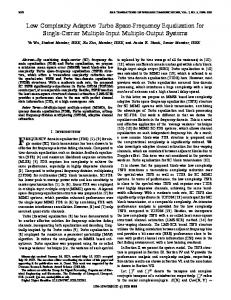
22.5" and all possible edge locations in the block are distinguished for each orientation. Fig. 1 shows the 13 chosen edge patterns, each of which has 4 isometries. The resulting error (< 11.25") in edge orientation is perceptually tolerable although it may result in significant RMS error. The flow diagram of the proposed coding scheme is shown in Fig. 2. The codmg scheme is discussed below in detail. x x x x . . . . .
x x x x x x x x
. . . .
. . . .
x x x x x x x x x x x x
. . . .
. . . .
x x x x
x x x x
x x x . x x . . x . . . . . . .
x x x x x . x . . . . .
. . . .
.
x x x x
0"
x x x x
x x . .
90"
. . . .
x x x x x x . . . . . .
. . . . . . .
x x x x x x x x x x . . .
. . . . . . .
x x x x x x x x .
x x x x x x x . x . . .
.
x x . . x . . .
x x x x
.
x x x .
x . . . . . .
x x . . x x . . X
.
.
~
.
x . . .
180"
270"
lock ~ l a s s i ~ c a ~ i o ~ We have used a simple and efficient method to classify blocks present in an image. In our scheme, the input image is first partitioned into 4x4 nonoverlapping range blocks and 8x8 overlapping domain blocks, where adjacent domain blocks in each direction are shifted by four pixels. The dynamic range D, of each range as well as averaged 4x4 domain block, which is the gray level difference between the bright and dark regions of a block, is computed for each pattern. If the maximum D, of a block, out of the 52 values, is greater than the Weber's threshold (Te), the block is assigned to the corresponding edge class, otherwise it is treated as a shade block. The value of Te is taken as 12 if mean intensity of the block lies between 36 and 220, and 18 otherwise. Since, in natural images many edges are continuous, the edge pattern present in a block can be predicted by checkmg for certain edge patterns in the appropriate neighboring blocks, as discussed in [lo]. For example, in Fig.3 if block B1 has edge pattern index 1, it can be predicted that block B, will have the same edge pattern. Since blocks B1 and I33 are closest to B,, the edge pattern is predicted by checking the neighboring blocks B1, B3, Bz and B4, in that order. The prediction process is terminated once an edge pattern is found in one of h e neighboring blocks in the order mentioned above. The status of pattern prediction is represented by a 1-bit id-code. Codmg of range blocks is &scussed in the next subsection.
Fig 1 : (a) 13 basic edge patterns (b) 4 isometries
A
Error c o d e
AV dom
Code Table formation
Fig 2: Block diagram of the proposed coding scheme.
Kumar and Jain: Low Complexity Fractal-Based Image Compression Technique
ii) Encoding of Shade Blocks We encode a shade block by using a novel and simple method which effectively reduces the intcrblock correlation present in its neighborhood. In our method (see Fig. 2), the error mean of a block is computed by subtracting the predicted mean from actual mean, where predicted mean is determined using neighboring shade blocks shown in Fig. 3, as described below.
Fig. 3 : Neighbouring blocks If B1 and B3 are shade blocks, the predicted mean would be the average of their coded (quantised) mean intensities. Otherwise, depending on the availability, the coded mean intensity of B1, B3, and B2, in this order, is taken to be the predicted mean. A 2-bit id is used to code the error mean Table I : Id Code for Error Mean
patterns are given in Fig. l(a). However, all the 52 edge patterns can be visualized by these 13 patterns with the help of 4 isometries (see Fig. I@)) for 'each given edge pattern. Only thirteen domain blocks are, therefore, finally retained out of 52 using maximum dynamic range criterion and their parameters mean, dynamic range, isometry and position information - are stored in the Code Table, where the position (x & y) of a domain block in the given image is represented by a 4-bit address. For each range block R,,a domain block D,, having the same edge pattern, is chosen from the Code Table. The complexity of this operation is O(n,). The affine transformation (TI) of the domain block DJ to the range block R, is found as shown below,
where, S is an operator that averages an 8x8 domain block to 4x4 and I, represents four isometries (i.e., 0", 90°, -90", 180"). a, (contrast scaling) and Ag, (luminance shift) are given
as, Reconstructed value
I Error mean I