Abstract. This paper describes a method to detect, measure the speed, and extract statistics of boats moving on a wide water surface using a single image ...
Boat Speed Monitoring using Artificial Vision Alberto Broggi, Pietro Cerri, Paolo Grisleri and Marco Paterlini VisLab - Dipartimento di Ingegneria dell’Informazione Universit` a degli Studi di Parma 43100 Parma, Italy {broggi, cerri, grisleri, paterli}@ce.unipr.it, web page www.vislab.it
Abstract. This paper describes a method to detect, measure the speed, and extract statistics of boats moving on a wide water surface using a single image stream taken from grayscale camera. The approach is based on a background subtraction technique combined with classification and tracking to improve robustness; it provides a stable detection even with sea waves and strong light reflections. The method returns correct speed values within the range ±5% in the 97% of use cases. The algorithm has been integrated in a speed warning prototype system on the Burano island in Venice, monitoring a 250 m wide channel slice. Images are captured by a high resolution camera and processed on site in real-time. Processing results can be accessed remotely for monitoring purposes. The system has been up and running for more than two years.
1
INTRODUCTION
The city of Venice has a naval traffic made by an almost unique concentration of different types of boats whose length varies from few meters to more than one hundred meters, and their shape can heavily change from one type to another. Many vessels cross water channels navigating too fast and generating huge sea waves. Waves are a critical problem for the city: they can damage both the buildings and also the ecosystem that lives on the natural coasts and has the property to contrasts the lowering of ground’s level. In order to solve this problem, a system to notify the boat drivers of their speed has been created with the aim of discouraging vessels driving too fast and therefore reducing the waves impact. Large speed panels are placed on the coast showing the current speed of boats passing through the channel. From the data collected during more than two years of continuous operation, it can be observed that boats reduce their speed after entering the measurement area. The goal of monitoring vessel speeds can be reached also by analyzing data provided by a radar, but in this case the system would be much more expensive than using a single camera. An example of this application has been presented by Blake in [1] but unfortunately, like described in [2] and [3] using a radar-based
method, it is difficult to recognize small boats, because their doppler spectrum is similar to sea waves’ spectrum. Vision based detectors offer great advantages since the classification capabilities are more precise than a radar (in a complex scene objects can be better distinguished and further classifications are possible).
(a)
(b)
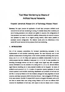
Fig. 1. The camera installed on Burano (Venice) island, a black arrow highlights the camera location (a), and channel to monitor with indication of distance and field of view (b).
Another system described in [10] has been realized in the city of Venice to monitor the traffic activity in the Grand Canal. The ARGOS system has a distributed structure, based on cells. Each cell has a vision sensor, a local processing unit, a Pan-Tilt-Zoom (PTZ) camera, and a wireless connection to a central server. The system proposed in this work has been designed to work with a single camera. It can deal with different target lengths, from small boats to big vessels: it has been tested successfully with ferries more than 100 meters long (longer than the framed area). A single camera, covering about 7500 square meters is placed on the channel side, fixed on a 10 meters tall pole, as shown in figure 1.a. In figure 1.b: point A shows the camera location, B and C represent points with well-known GPS coordinates; the yellow area depicts the camera field of view. Notice that the camera is installed about 40 m far from the beginning of the detection area. The camera is connected to a computer for local data processing. The system is connected through a standard ADSL line and can be monitored via browser thanks to a dedicated and integrated web server. The system collects statistics about the observed traffic and for each target it logs the speed of boats when entering the monitored area, when leaving it, the average speed, and the time of observation.
2
BOATS DETECTION
This section describes the various phases of the detection algorithm. The system, from a high level point of view, is organized into a three stages pipeline: the first stage takes a 256-levels grayscale image acquired from the camera as input and produces a 2 levels image representing pixels belonging to the background and pixels belonging to features of moving objects; the second section analyzes these 2-level images in the time domain to detect boats in the scene, tracking them, and calculating their speed, using camera calibration data. The assessment of determining the boat speed with a good accuracy requires the determination of the target position with high precision. A tide compensation procedure has also been introduced into the system to reduce errors due to incorrect positioning of the boat baseline. The third level carries over all other service tasks such as supervising the log composition and, publishing the output image on the web page. 2.1
Improving Background Subtraction
This section describes how to improve the well-known background subtraction technique to detect moving objects for this very specific application. The main issue consists in creating a suitable reference frame that is able to filter sea waves. In the literature different approaches are presented which describe how to detect moving object in indoor or structured outdoor scenes, but in this case we had to consider outdoor scenes, in which the background changes very quickly like water background. Different statistical approaches has been proposed such as [4] and [5]. The algorithm described in this article draws on Alsaqre’s[6] method to calculate a reference frame as the union between the current frame and the previous reference frame. Other more recent approaches like [11] are based on saliency. In the proposed system raw images are processed to obtain the reference frame using equation (1), where r represents a pixel of the reference frame and, c a pixel of the current frame. r = (1 − 0.25) ∗ r + 0.25c
(1)
By using equation (1), pixels representing sea and sea waves become similar. This is a useful result since waves disturb the detection of moving objects. The reference frame is shown in figure 2.b. Now, background subtraction is applied between the current frame and the reference frame, obtaining the image shown, with inverted colors, in figure 2.c. After binarization some noise may still be present, as shown in inverted colors, in figure 2.d, mainly due to non completely filtered waves. To reduce and possibly remove it, the algorithm searches for connected regions larger than a fixed threshold and removes smaller regions. Although the background subtraction method used here is simple and well known quite old it has been chosen over newest approaches available in literature
(a)
(b)
(c)
(d)
(e)
(f )
Fig. 2. Raw frame (a) and reference frame (b). With inverted colors: difference frame (c) and binarized difference frame (d). Connected regions (e) and bounding boxes (f )
thanks to its simplicity, the possibility to be executed in a short time, and eventually implemented in hardware. Figure 2.e shows, in inverted colors, the resulting image after the filter application, with a strong noise reduction compared with the image shown in figure 2.d. Each connected region is then labeled using a unique bounding box that has a numeric identifier as shown in figure 2.f. 2.2
Tracking
This section explains how the tracking process is realized. The algorithm analyzes each connected region (i.e moving objects’ features) searching for its movement from the previous frame to the current one. In particular, each feature in the current frame is compared to all those in the previous frame, in order to locate and match the very same feature. Similarity rules are used to evaluate the matching between two features are similar. Three parameters are used: – Aspect ratio match, – Area match, – Content match. Each comparison returns a floating point match value. These values are then filtered using a triangular fuzzy function to normalize the results. The function slope has been adjusted during the in-lab development on pre-recorded sequences. After that, all these outputs are multiplied together, so that a single comparison match value equal to zero causes a null final match value. The algorithm compares every bounding box of the current frame with every bounding box of the past frames. The average among the three match values was also considered, but it can lead to errors in some cases, so a new match value has been defined to be the final one. The comparison process between bounding boxes has been extended up to the last five frames in the past, in order to reach a more robust result. All match values are accumulated together to obtain a unique match value for each feature in the current frame. When possible, every feature in the current frame is linked to one feature only of the previous frame. For each feature in the current frame, it is now possible to determine the correspondent motion vector, which links two bounding boxes’ centers (figure 3) and which also has a weight, given by the features’ characteristics. Vectors are clustered using similarity rules, depending on module and phase. The time analysis of the motion vectors associated to each feature is the basis of the next high level processing step. 2.3
High level processing
The algorithm evaluates the motion vectors for each feature, looking for affinity in contiguous time steps. A new target is created when the algorithm finds similar
Fig. 3. Moving object features and corresponding motion vectors represented by red arrows.
vectors in contiguous time steps, meaning that two or more features are moving in the same fashion and are therefore clustered together. This event implies a new target creation, which is identified by a bounding box and which has some distinctive features such as: unique identifier, geometric qualities, position coordinates, motion vector. When new target features are identified, the target geometry changes. The main purpose of the system is to measure the boat speed; this problem is directly mapped into measuring the speed of the boat features. The system provides a correct detection even if the silhouette of the boat is not completely visible, such as boats longer than 100 m which do not fit into the camera field of view. The target base line, represented by the lower bound of the target’s bounding box, is used to evaluate the target speed value. It is the only available means to estimate the distance between the target and the camera, since the system is based on monocular vision. The baseline detection uses as features the wavelets at the boat base. This effects increase with the boat speed.
3
SPEED ESTIMATION
The module of the target’s motion vector represents the speed value, measured in pixel/f rame. Using camera calibration, frame rate, and the target’s base line, it is possible to estimate the actual boat speed value measured in km/h. Wrong estimations may occur when the algorithm is not able to correctly detect the target’s base line. The use of a camera resolution of 1024 × 768 pixel makes it possible to decrease the probability of this kind of errors by hooking as features the small and regular wavelets the water shapes at the base of the
boat. In figure 4.a, the x-axis plots the base line errors, measured in pixel; the y-axis represents the corresponding speed errors. Many functions are plotted on the graph, depending on the current target’s speed. For example when a target is moving at 45 km/h, a +30 pixels base line error (vertical) introduces a speed error of 4.9 km/h, about 5% of the actual speed. After a number of experimental tests carried over 3 months of tests it is possible to state that the maximum base line error is not higher than 5 pixels, corresponding to a 2% maximum speed error.
(a)
(b)
Fig. 4. Error produced by a wrong detection of the target’s base line (a). Error produced by the tide level (b).
3.1
The influence of tide
A further source of errors is the tide level, that changes many times during the day, and that behaves differently depending on atmospheric conditions and season. In the gulf of Venice, the maximum tide range can reach 2 m [−1 m, +1 m] under particular conditions. The water level acts as the reference plane: changing the water level is like changing the plane where targets are moving or changing the camera height. Errors due to tide level are described in figure 4.b: the x-axis plots the tide level, measured in meters; the y-axis indicates the corresponding speed errors. Many functions are plotted, depending on the target speed. For example, when a target is moving at 20 km/h, and the tide level is 70 cm, the error on the estimated speed for a boat 200 m far from the camera will be 4.8 km/h, comparable to 24% of its actual speed. It is clear therefore that the tide’s level can not be ignored. As mentioned, the tide level is given by the composition of two effects: astronomical effect (given by the specific position
of the moon and the sun, which is predictable) and weather (especially wind blowing from south to north, which is unpredictable but measurable). In this work the tide level is provided by astronomical considerations, which represents a reasonable first order approximation. This is the easiest way to estimate the tide, because it does not imply any other tool installation, like for example a float sensor.
4
RESULTS
Results tightly depend on the type of vessel entering the camera view, on vessels’ shape and color, and lighting conditions; so it is therefore difficult to provide absolute results. Quantitative performance analysis has been carried out on different video sequences totaling about 1.5 hours which showed 87 correctly detected targets and only 2 missed over. The system returns correct results with a very limited number of false positives; false negatives events are generally due to low lighting conditions. Results are good even when more then one target enter the camera view shot. In case of adverse weather conditions, the algorithm also returns correct results, as shown in figure 5.a which was recorded during a snow storm with high winds blowing, generating both waves and a sensible camera pitch vibration. When the boats direction is not orthogonal to the projection of the camera optical axis on the sea surface, boats can be seen as moving diagonally in the framed image, as that depicted in figure 5. In these cases, the speed measurement still remains below 5% boundary since the lower side of the bounding box surrounding the target has a corner belonging to the boat baseline. Despite this, the geometry allows to correctly estimate the vessel speed. In correspondence to situations in which two vessels move in opposite directions, the algorithm returns two separate speed estimates which are displayed on two different panels. Figure 5.b shows two additional windows indicating the output values displayed on the hardware panels. At the end of the development, the system was tested with motorboat equipped with a differential GPS. 8 hours of continuous tests with different speeds, distance from the camera, different scenario configurations (single boat, multiple boats with same and different directions), different illumination conditions have been concluded successfully. The error was measured to remain under the 5% of the GPS measurement.
5
CONCLUSION and FUTURE WORK
The system has been operational at the test site for more than two years and during this period the whole system has proven to be effective. From the logs analysis, the boats speed tends to be reduced as long as they pass in the monitored area. A further step of this work is the porting of the whole detection algorithm on an embedded architecture like a smart camera integrating both the sensor and an embedded processing system. This integration would allow to
(a)
(b)
Fig. 5. Successful operations during bad weather conditions (a). A double vessel transition (b) in opposite directions: both speeds are reported.
cut on price and simplify the system installation phase. Even if the proposed system has already reached significant results, some useful improvements can be made. First, automatic camera gain control process is needed to correct false negatives generated by low light conditions. The use of a second camera into the system may provide a number of improvements, solving for example errors generated by the tide level. In fact, stereo vision would make it possible to compute, the distance between the target and the camera with higher precision than a monocular-based system. On the other side, in order to detect targets placed 200 m far away from the camera system, it would be necessary to place the two cameras at a distance of about 2 m from each other. This implies to realize a tough infrastructure able to resist to adverse weather conditions, like high winds.
6
ACKNOWLEDGMENTS
This work was funded by Ministry of Infrastructures and Transports - Magistrato delle acque through its concessionary “Consorzio Venezia Nuova” in the framework of the project ”Interventi di protezione di margini barenali in erosione nell’area del canale di Burano. Progetto esecutivo Monitoraggio delle opere. Sperimentazione di un dissuasore di velocit`a natanti”. The authors also gratefully acknowledge the grant provided by Tattile and Thetis as a support to this research.
References 1. T.M.Blake. Ship Detection and Tracking using High Frequency Surface Wave Radar. In HF Radio Systems and Techniques, pp. 291–295. Nottingham, UK, lug. 1997. 2. Herselman, P. L.; de Wind, H. J. Improved covariance matrix estimation in spectrally inhomogeneous sea clutter with application to adaptive small boat detection. In 2008 International Conference on Radar , pp. 94-99. Adelaide, Australia, 2-5 Sept. 2008
3. P. L. Herselman and C. J. Baker, Analysis of calibrated sea clutter and boat reectivity data at c- and x-band in south African coastal waters In RADAR 2007 , 2007. 4. S. Muller-Schneiders, T. Jager, H. S.Loos, W. Niem e R. B. GmbH. Performance Evaluation of a Real Time Video Surveillance System. In 2nd Joint IEEE International Workshop on VS-PETS , pp. 137–141. Beijing, China, Oct. 2005. 5. N. Ohta. A Statistical Approach to Background Subtraction for Surveillance Systems. In IEEE International Conference of Computer Vision, pp. 481–486. 2001. 6. F. E. Alsaqre e Y. Baozong. Multiple Moving Objects Tracking for Video Surveillance Systems. In the 7th International Conference on Signal Processing (ICSP04), pp. 1301–1305. Beijing, China, 2004. 7. M. Seki, H. Fujiwara and K. Sumi. A Robust Background Subtraction Method for Changing Background. In IEEE Workshop Applications of Computer Vision, pp. 207–213. 2000. 8. R. Cucchiara, C. Grana, M. Piccardi and A. Prati. Detecting Moving Objects, Ghosts, and Shadows in Video Streams. In IEEE Transactions on Pattern Analysis and Machine Intelligence, Vol.25, No.10 , pp. 1337–1342. Oct. 2003. 9. M.Paterlini Progettazione e realizzazione di un algoritmo di visione artificiale per il monitoraggio della velocit` a dei natanti. Master Thesis. A.A. 2005-2006 Dip. Ing. Inf, Universit` a degli Studi di Parma, Italy. 10. D. Bloisi, L.Iocchi, G.R.Leone, R.Pigliacampo, L.Tombolini and L.Novelli A distributed vision system for boat traffic monitoring in the Venice Grand Canal. In 2nd International Conference on Computer Vision Theory and Applications (VISAPP-07). 8 - 11 March, 2007 Barcelona, Spain. 11. V. Mahadevan, N. Vasconcelos Background Subtraction in Highly Dynamic Scenes IEEE Conference on Computer Vision and Pattern Recognition, 2008. CVPR 2008. 23-28 June, 2008, Anhorage, Alaska. 12. Ministry of Infrastructures and Transports - Magistrato delle acque through its concessionary “Consorzio Venezia Nuova” - ”Interventi di protezione di margini barenali in erosione nell’area del canale di Burano. Progetto esecutivo Monitoraggio delle opere. Sperimentazione di un dissuasore di velocit` a natanti”.