BPS: A Bufferless Switching Technique for NoCs∗ Crisp´ın G´omez
Mar´ıa E. G´omez Pedro L´opez Jos´e Duato Dept. of Computer Engineering, Universidad Polit´ecnica de Valencia, Camino de Vera, s/n, 46071–Valencia, Spain
[email protected],{megomez,plopez,jduato}@disca.upv.es January 7, 2008
1
Introduction
from different perspectives the use of multiple parallel channels on the same direction, known as Space Division Multiplexing (SDM). The results show that SDM is a good approach that can increase the system performance without increasing the switch complexity, area and power consumption. In fact, power and area consumption are two main constraints in on–chip networks. Several previous works [2, 4, 11] show that a high percentage of both, total switch area and power, is consumed by the buffers located at the switch ports, and, therefore, reducing their size is an objective of NoC designers. Additionally, in a recent work [7], the authors show that as the buffer size at the switch is decreased, the switch frequency can be increased. In particular, by eliminating the buffers at the switch ports and replacing them by one–flit latches, they can increase the switch frequency from 1GHz up to more than 2GHz. This is due to the fact that the critical path is reduced since the buffering architecture at the switch ports requires some control logic whose delay adds up to data–path delay and limits the switch frequency. In this paper, we take advantage of this idea to propose a new switching technique with the aim
Wires are an abundant resource in on-chip networks. This wiring capability has led to networks with very wide links, compared with the ones that we can find on off-chip networks. As an example of such systems, in [2, 8], two different NoCs are proposed with link widths of 80 and 256 bits, respectively. These wide links provide low latency communication between the nodes of the network because the packet is composed by a low number of flits. However, there are a high number of systems that can not take advantage of these wide links, because their packet size is small and they cannot fulfill the link width. For instance, in [1, 9], the authors present two systems whose smallest packet size is 64 bits. These packets will waste a link more than 64 bits wide since only part of the link will be used. Several previous works also propose to use multiple parallel channels in the same direction to exploit the high wiring capability available in NoCs [3,6,10]. The authors of these works study ∗
This work was supported by the Spanish MEC under Grant TIN2006-15516-C04-01 and by CONSOLIDERINGENIO 2010 under Grant CSD2006-00046 and the HiPEAC network of excellence..
1
there is not an available output port for a packet after arriving to a switch, this packet will be discarded. In other words, packets are treated like a moving information flow that can not be stopped once it has been injected into the network. It must advance through the network or it will be discarded. If this flow (the packet) can not find a free output port, the packet will be discarded. So, packets does not suffer contention (but actually there may be some packet reinjections, see below). For this, we call the technique Blind Packets Switching (BPS) since packets are not aware about the output ports availability. In order to decrease the probability of discarding packets, we propose the use of SDM. SDM can be efficiently used to increase the number of parallel links in the same direction, taking advantage of the vast wiring capability of NoCs, as it was explained in [3]. In this way, the probability of finding a free output port when arriving to a switch is increased, and, therefore, the number of dropped packets is expected to be decreased. SDM reduces the number of discarded packets but does not eliminate them. There may still be some packets that can not find a free output port. On the other hand, discarded packets can not be lost. The packet must reach its destination. For this, our switching technique implements a negative acknowledge (NACK) mechanism. The switch that drops a packet sends a NACK back to the source of the dropped packet. Once the NACK reaches the source of the packet, it is reinjected into the network. Notice that NACK packets could be dropped, as they use the same channels that the data packets. However, in this case, the NACK is stored in a little buffer in the switch, since NACKs are critical data. This NACK queue has priority over the other links inside the switch, in such a way, that if a normal data packet and the NACK queue pretend to use the same output port, the port will be granted to the NACK queue. In this way,
of decreasing the power and area consumption and, moreover, allowing the switches to work at a higher frequency, which will permit the network to achieve a higher performance.
2
Proposal
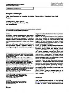
The basic idea of our proposal is simple. As buffers are the most consuming part of the switch in terms of power and area, also limiting the switch frequency, we propose to remove them from the switch. Figure 1.(a) shows a switch with input and output buffers, buffers can be composed by multiple latches serially connected plus some control logic. Every latch can store a flit. Notice, that only one input and one output port of the switch are shown. Figure 1.(b) represents our proposed switch. Input and output queues have been reduced to just one flit per port and, therefore, buffer control logic has been removed. These latches actually work as repeaters, they do not store the flits while packets are waiting for routing or due to congestion. They only store a flit during a clock cycle. As stated in the introduction, this switch can work approximately twice its usual frequency [7]. Since there are not buffers to store the packets, there must be some mean to store them. Our proposal is to use the wires instead of the buffers. But, this has a huge limitation, as a wire can only store the information while the packet is going through it. The wire can not store the packet while waiting for a resource. If a header flit reaches a switch and this switch does not have any element to store it, the flit will be discarded, and also the rest of flits of the packet when arriving to this switch. The latches in our switch only store a flit during a clock cycle in order to provide storage space to the incoming flits that are traveling through the link. As the flits are not stored for more than one clock cycle, if 2
Control Logic
Latch
Latch
. . .
Latch
Latch
Crossbar
Output Latch
Crossbar
Latch
Input Latch
Output Queue Latch
. . .
Latch
Latch
Input Queue
Control Logic
(a)
(b) Figure 1: (a) A classic switch with both input and output queues. (b) Our proposed switch. NACK losing can be avoided.
3
Latch
Latch
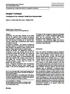
Routing The number of dropped packets can be reduCircuitry ced even more by using misrouting. Every time a packet can not use an output port that moves Crossbar it closer to its destination, other available output port is used, but the packet is not discarded. However, the number of times that a packet can use non-profitable output ports is limited with Figure 2: Detailed input port in a switch with the aim of preventing livelocks. routing time of 1 clock cycle. In order to guarantee an efficient operation of our proposal, we must avoid any delay that ma- to the routing circuitry, being stored in it during kes the packet to stop, since no buffers are availa- the routing cycles. Data flits just go through ble to store it. For instance, when a packet arri- the latch chain, maintaining in this way the corves to a switch, it must be routed which usually rect flow of the packet. Notice that this chain takes more than a clock cycle. Furthermore, this of latches does not work as a buffer (every latch delay only affects the header flit, while the data holds the flit just one clock cycle), therefore, the flits are not affected. During the routing cycles, switch can keep working at the increased frethe header flit is stored in the routing hardware quency (close to twice the usual frequency) since while the rest of the flits have no buffers to be it is not in the critical path. Data flits arrive to stored while the routing decision is taken. Data the first latch while the header flit is in the rouflits must wait for the routing decision and the ting circuitry and remain in the chain until the header flit transmission since they can not over- header flit is transmitted to the output port. come the header flit. The way we propose to Another crucial issue to avoid discarding solve this problem is to delay the data flits as packets is the availability of the routing circuitry. many cycles as the routing delay. This can be If the header of a packet reaches a switch and the done with a chain of n latches, being n the rou- router is busy due to other packets, the packet ting delay in clock cycles. Figure 2 shows an will be dropped. So, there should be an available example in a switch with routing delay equal to router to deal with arriving packets. We propose one clock cycle. Packet header traverses the first to arrange multiple parallel routers per switch, in latch in the input port, and then it is redirected order to decrease the number of dropped packets.
3.2
Notice that no flow control mechanism is needed. The switch does not use information about buffer availability when routing packets, since there are no buffers. Also, deadlock recovery or avoidance mechanisms are not necessary, since deadlocks can not occur because packets are never stopped.
3 3.1
Evaluation Results
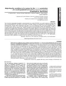
In order to evaluate our proposal, we are going to compare it with wormhole switching, first, with the same crossbar complexity, and, second, with the same link configuration. In the figures of this section, clock cycle is measured in our switch cycle. Notice that wormhole cycle corresponds to two of our cycles, as we are assuming that our switch is working at twice the frequency of the buffered wormhole switch. As an example, in Figure 3.(a), we show the network throughput versus the packet latency for our proposal and wormhole under the same crossbar complexity for a 8 × 8 mesh. Wormhole configuration has only one 256 bits link for each direction, and each link has four virtual channels. Our proposal has four 64 bits physical links per direction. In total, both systems have 256 wires and 4 crossbar connections per direction. Packet size is fixed for both systems to five times the link width of the wormhole system (1280 bits), so packets can take advantage of 256 bits links. As it can be seen in the figure, despite that packets have four times more flits in our proposal, it can achieve a smaller latency than wormhole. Furthermore, throughput is increased approximately by a 17%. Also, we can observe the increase in latency for the wormhole system as the injection rate is increased, since the congestion in the network is also increased. In our proposal, we can observe that the evolution of the latency is more stable, and only at high injection rate the latency is slightly increased. At medium and low injection rates, our proposal is not so affected by congestion, because the low amount of congested packets are discarded (they will be reinjected) and do not stop other packets spreading the congestion to the whole network. In Figure 3.(b), we present a similar graph to the previous one. In this case, both configurations have the same number and width of links
Evaluation Simulation Environment
For the performance evaluation of our proposal, two detailed event-driven simulators have been developed. The simulators model a mesh network with point-to-point bidirectional serial links with variable width. One of the simulators implements wormhole switching, while the other one implements our switching technique. Each router has a non-multiplexed crossbar. In the case of the wormhole simulator, switches has both input and output buffers, and each virtual channel buffer can store three flits, being the flit size equal to the phit size (to the channel width). Packets are adaptively routed through minimal paths. In the case of the wormhole simulator, two virtual channels are required and Duato’s protocol [5] is used. For our proposal, adaptive routing does not require any virtual channel since deadlocks can not appear. Multiple parallel links in the same dimensions are allowed. Additionally, a switch can connect multiple nodes to the network and every node can have multiple injection and extraction channels. We assume that the packet generation rate is constant and the same for all the nodes. The destination of a packet is randomly chosen with the same probability for all the nodes. Routing time, link time and crossbar time are supposed to be one cycle. 4
120 WH 256 bits channel 4VCs BPS only reinjections
Average Message Latency (cycles)
Average Message Latency (cycles)
90 80 70 60 50
110 100
Wormhole BPS
90 80 70 60 50 40 30
2
3
4 5 6 7 Traffic (bytes/cycle/node)
8
9
1
(a)
2 3 4 5 Traffic (bytes/cycle/node)
6
(b)
Figure 3: Latency versus throughput of a 8 × 8 mesh with one core per switch and 4 injection and extraction channels per core for wormhole and BPS. (a) Wormhole with one 256 bits channel per direction and 4 virtual channels. BPS with four 64–bit channels per direction. (b) Both switching techniques with four 64–bit channels per direction. the number of reinjected packet is a 5% of the number of total packets. As it can be seen from this preliminary evaluation, our switching technique is able to improve performance while reducing the number of buffers and, therefore, reducing the area and power consumption.
per direction. As commented before, wormhole switching needs two virtual channels per physical one to provide deadlock–free routing. So, wormhole switching has eight virtual channels per direction, and the needed crossbar is four times the needed one for our proposal. Both systems model a cache coherence system, whose packet sizes and percentages are the same that were used in [1, 3]. Two packet sizes are used. Short packet size is 64 bits and large packet size is 576 bits. The percentage of short packets is 60%. In this case, throughput is increased by a 47% and latency is roughly reduced by a 50% with our proposal.
References [1] J. Balfour and W. J. Dally, Design tradeoffs for tiled CMP on-chip networks, Proc. of the 20th Annual Int. Conf. on Supercomputing, 187–198, 2006.
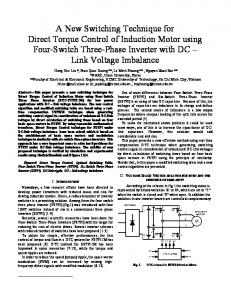
Figure 4 shows the results for our proposal [2] W. J. Dally and B. Towles, Route packets, not using the same configuration as in Figure 3.(b) wires: on-chip inteconnection networks, Proc. of with and without misrouting. The maximum the 38th Conf on Design Automation, 684–689, number of misroutes is fixed to two. In Figure 2001. 4.(a), we can observe that throughput is increa[3] C. G´omez, M.E. G´omez, P. L´ opez and J. Duato, sed by a 17% when misrouting is used. But, the Exploiting Wiring Resources on Interconnection main advantage of misrouting is shown in Figure Network: Increasing Path Diversity, Proc. of the 4.(b). Using misrouting, the number of reinjec16th Euromicro Int. Conf. on Parallel, Distributed packets is practically zero. In the worst case, ted and Network-Based Processing, 2008. 5
Without misrouting With misrouting
38
Reinjected packets (Percentage)
Average Message Latency (cycles)
25
40
36 34 32 30 28 26
Without misrouting With misrouting
20 15 10 5 0
1
2
3 4 5 Traffic (bytes/cycle/node)
6
7
1
2
3 4 5 Traffic (bytes/cycle/node)
6
7
(a) (b) Figure 4: Results for BPS in a 8 × 8 mesh with and without using misrouting, four 64–bit channel are used per direction. (a) Latency versus throughput (b) Percentage of reinjected packets versus throughout. [4] G. De Michelli and L. Benini. Network on chips, Morgan Kaufmann, 2006.
Proc. of the 19th IEEE Int. Parallel and Distributed Processing Symp., 2005.
[5] J. Duato, S. Yalamanchili and L. Ni, Interconnec- [11] T. Ye, L. Benini and G. De Micheli. Packetization and Routing Analysis of On-Chip Multiprotion Networks. An Engineering Approach, Morcessor Networks, Journal of System Architecture, gan Kaufmann, 2004. vol. 50, 81-104, 2004. [6] A. Leroy et al, Spatial division multiplexing: a novel approach for guaranteed throughput on NoCs, Proc. of the 3rd IEEE/ACM/IFIP Int. Conf. on Hardware/software Codesign and System Synthesis, 81–86, 2005. [7] F. Martini, D. Bertozzi, and L. Benini, Assessing the Impact of Flow Control and Switching Techniques on Switch Performance for Low Latency NoC Design, in the First Workshop on Interconnection Network Architectures: On-Chip, Multi-Chip, 2007. [8] R. Mullins, A. West and S. Moore, The design and implementation of a low-latency on-chip network, Proc. of the 11th Asia and South Pacific Design Automation Conf., 164–169, 2006. [9] S. Vangal et al, An 80-tile 1.28TFLOPS networkon-chip in 65nm CMOS, Proc. of the Int. SolidState Circuits Conf., 2007. [10] P. T. Wolkotte et al, An Energy-Efficient Reconfigurable Circuit-Switched Network-on-Chip,
6