BRDF Effects Based on Optical Multi-Angular Laboratory and Hyperspectral UAV Measurements Peter Roosjen, Harm Bartholomeus, Juha Suomalainen and Jan Clevers Laboratory of Geo-Information Science and Remote Sensing, Wageningen University, P.O. Box 47, 6700 AA Wageningen, The Netherlands Contact:
[email protected]
Introduction
UAV flight pattern
Bidirectional Reflectance Distribution Function (BRDF) effects are a commonly known source of error in remote sensing data. The aim of this study was to investigate and compare BRDF effects observed under laboratory conditions using a goniometer, and under natural conditions, using an unmanned aerial vehicle (UAV).
12° tilt of the sensor
Laboratory goniometer measurements The laboratory goniometer facility [1] of Wageningen University was used to measure the BRDF of sugar beet plants, collected from the field that was measured by the UAV. The measurements were taken from a distance of 1 meter using an 8° foreoptic. Setup during the laboratory measurements
More info:
Figure 4. The hyperspectral sensor was tilted 12°. By flying towards and away from the sun with the sensor pointed towards or away from the sun, pixels were captured in the principal plane with view zenith angles up to 34°.
Figure 1. The laboratory goniometer facility. The setup consists of an industrial robot arm on which a spectrometer is mounted. The custom software that drives the setup allows for fully automated reflectance measurements over the complete hemisphere.
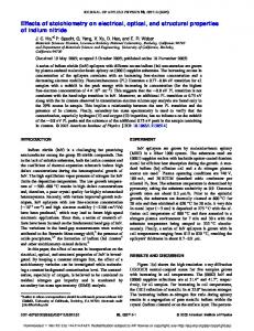
Figure 5. The UAV flight over the sugar beet field projected on a RGB orthomosaic. The UAV was flying at an altitude of 80 m, resulting in a scan line of just over 60 m with approximately 20 cm pixels. For each pixel, the observation azimuth and zenith angles were calculated.
Goniometer results
UAV results
Figure 2. Red and NIR reflectance factors of a sugar beet plant measured in the principal plane. The illumination source was placed at a -30° zenith angle.
Figure 6. Red and NIR reflectance factors of the sugar beet field of pixels within a 5° azimuth distance of the principal plane. The sun zenith angle was at -30°. Both the goniometer and UAV data sources show a similar trend in forward and backward scattering intensity. Further analysis of the data is still in progress.
UAV measurements
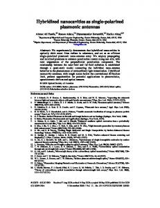
Red
Figure 7. Red and NIR reflectance factors over the full hemisphere, collected by the UAV. The top figures show all individual pixels and the bottom figures show the average of all pixels within a 15° azimuth and 5° zenith interval. The bottom figures show a clear increase of reflectance factor in the back scattering direction. Sun positon is 30° zenith and 198°201° azimuth.
The hyperspectral mapping system (HYMSY, [2]) was used to capture BRDF effects under field conditions. The hyperspectral pushbroom sensor was tilted 12° to create a field of view (FOV) up to 34°. BRDF effects in the solar principal plane were captured by flying the UAV with the FOV pointed towards and away from the sun. Hyperspectral Pushbroom Spectrometer More info:
400–950 nm 9 nm FWHM 25 lines/s 328 px/line
Figure 3. The HYMSY, a lightweight hyperspectral mapping system, carrying a pushbroom spectrometer, a photogrammetric camera and a GPS-Inertial Navigation System. Typical products are a RGB orthomosaic (1–5 cm resolution), a digital surface model (5–10 cm resolution) and a hyperspectral datacube (10–50 cm resolution).
Laboratory of Geo-Information Science and Remote Sensing P.O. Box 47 6700 AA Wageningen Contact:
[email protected] T + 31 (0)317 48 35 08, M +31 (0)6 17 423 235
NIR
References [1] Roosjen, P.P.J., Clevers, J.G.P.W., Bartholomeus, H.M., Schaepman, M.E., Schaepman-Strub, G., Jalink, H., van der Schoor, R., & de Jong, A., “A Laboratory Goniometer System for Measuring Reflectance and Emittance Anisotropy”, Sensors, 2012, 12, 17358-17371. doi:10.3390/s121217358 [2] Suomalainen, J., Anders, N., Iqbal, S., Roerink, G., Franke, J., Wenting, P., Hünniger, D., Bartholomeus, H., Becker, R. & Kooistra, L., “A Lightweight Hyperspectral Mapping System and Photogrammetric Processing Chain for Unmanned Aerial Vehicles”, Remote Sensing, 2014, 6, 11013-11030. doi:10.3390/rs61111013