Dario Alasia, Stella Foaleng Mafang, Sanghoon Chin, and Nikolay Primerov, for their ... Kwang-Yong Song from Chung-Ang University in Seoul, for their key.
Front. Optoelectron. China DOI 10.1007/s12200-009-0086-9
REVIEW ARTICLE
Brillouin distributed time-domain sensing in optical fibers: state of the art and perspectives Luc THÉVENAZ (✉) Ecole Polytechnique Fédérale de Lausanne, Institute of Electrical Engineering, Lausanne 1015, Switzerland
© Higher Education Press and Springer-Verlag Berlin Heidelberg 2010
Abstract Optical fiber sensors based on stimulated Brillouin scattering have now clearly demonstrated their excellent capability for long-range distributed strain and temperature measurements. The fiber is used as sensing element, and a value for temperature and/or strain can be obtained from any point along the fiber. After explaining the principle and presenting the standard implementation, the latest developments in this class of sensors will be introduced, such as the possibility to measure with a spatial resolution of 10 cm and below while preserving the full accuracy on the determination of temperature and strain. Keywords optical fiber, optical fiber sensors, distributed fiber sensors, stimulated Brillouin scattering, nonlinear fiber optics
1
Introduction
Distributed Brillouin sensing was first proposed in the late 1980s as an alternative technique to the classic optical time-domain reflectometry (OTDR) to measure local attenuation along an optical fiber [1]. It turned out rapidly that it had many more potentialities for sensing, since Brillouin scattering is intrinsically very sensitive to temperature and the deformations experienced by the sensing fiber [2,3]. This comes from the property that Brillouin scattering must satisfy a very strict phasematching condition, making the interaction to manifest as a spectrally narrow resonance. For a spontaneous scattering, the scattered light will present a sharp spectrum peaking at a frequency shifted from the pump by the quantity [4]: nB ¼
2nVa , lo
Received August 1, 2009; accepted October 30, 2009 E-mail: luc.thevenaz@epfl.ch
(1)
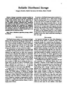
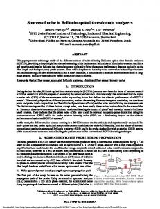
commonly named Brillouin frequency shift, where n represents the effective refractive index of the propagating mode, Va is the acoustic velocity in the fiber (~5800 m/s), and lo is the vacuum wavelength of the incident light. For a stimulated scattering, a weak signal wave will experience a sharp gain if it is spectrally positioned at a frequency shifted by nB below a strong pump propagating in the opposite direction through the fiber. As expressed in Eq. (1), the Brillouin frequency shift nB is very dependent on the acoustic velocity and any change of this velocity will be observed as a spectral shift of the resonance. In a solid, the theory of elasticity gives the following general dependence for the acoustic velocity [4]: sffiffiffiffi K Va ¼ , (2) � where K is the bulk modulus and r is the material density. The density of the material r is temperature-dependent as a result of the thermal expansion, so that the peak frequency of the interaction is observed to change with the temperature. This is illustrated in the top part of Fig. 1, showing a measurement of the gain experienced by the signal as a function of the frequency difference between pump and signal, for different temperatures [5]. Any deformation experienced by the fiber will also have an impact on its density r, and this property is particularly exploited to use the fiber as a distributed strain gauge, by observing the shift of the resonance when the fiber is elongated, as shown in the bottom part of Fig. 1. Therefore, temperature and strain can be evaluated using Brillouin scattering by determining the frequency difference between pump and signal that gives the maximum interaction. It is remarkable that the relationship between these two quantities and the Brillouin shift nB is very linear, as shown in Fig. 2 [5]. From the point of view of the measuring potentialities, Brillouin-based techniques bring the following advantages over other distributed techniques:
2
Front. Optoelectron. China
2) It is a frequency-based technique as opposed to Raman techniques that are intensity-based. Brillouin techniques are consequently inherently more accurate and more stable on the long-term, since intensity-based techniques suffer from a higher sensitivity to drifts and from a potential biasing by any step loss. 3) Since the information is not a consequence of the background thermal activation, experimental solutions based on stimulated Brillouin scattering can be exploited, leading to a much greater intensity of the scattering mechanism and consequently a more acceptable signal-to-noise ratio. The different implementations for distributed Brillouin sensing will be reviewed hereafter.
2 Brillouin optical time-domain reflectometry (BOTDR)
Fig. 1 Measurement of gain experienced by a signal through stimulated Brillouin scattering as a function of frequency difference between pump and signal. (a) Gain obtained for different temperatures; (b) gain obtained for different longitudinal strains applied to the fiber, showing Brillouin frequency shift dependence on environmental quantities
Fig. 2 Relationship between two quantities and Brillouin shift in a standard single-mode fiber for a 1550 nm pump wavelength. (a) Longitudinal strain applied to the fiber (strain coefficient: 505.5 MHz/%); (b) temperature (temperature coefficient: 0.95 MHz/°C)
1) The technique makes use of standard low-loss single-mode optical fibers offering several tens of kilometers of distance range and a compatibility with telecommunication components.
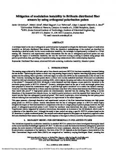
This technique is very similar to the Rayleigh-based OTDR and the spontaneous Brillouin light backscattered from an intense pulse is recorded as a function of time [6]. To extract the local frequency distribution, the backscattered signal is optically mixed with the continuous wave (CW) light from the laser and the detected beat signal is then electrically mixed with a microwave local oscillator. The recorded signal will then be proportional to the optical beat amplitude at the frequency of the microwave oscillator. By scanning step-by-step the frequency of the microwave oscillator and by recording for each step the mixed signal in the time domain, the frequency distribution of the backscattered signal can then be reconstructed at each position by analyzing for each time step the amplitude as a function of frequency and determining the peak value. A block diagram of a typical BOTDR setup is sketched in Fig. 3.
Fig. 3 Block diagram of a typical BOTDR setup
The Brillouin backscattered signal being 100 times smaller than Rayleigh backscattering, the detection scheme must be particularly efficient and sensitive while offering a bandwidth >10 GHz. The backscattered signal, however, benefits from the coherent mixing with the pump and also
Luc THÉVENAZ. Brillouin distributed time-domain sensing in optical fibers
frequently from amplification by the pulse through stimulated Brillouin scattering. This does not have an impact on the measurement accuracy, since the information is not contained in the signal amplitude and such amplification does not bias the frequency content. The spatial resolution is practically limited to 1 m for the following reasons: if the pulse spans over a bandwidth larger than the Brillouin gain spectrum, the backscattered signal will show a broader spectral distribution given by the convolution of the natural Brillouin gain distribution with the pulse spectrum. This will smear out the backscattered signal over a wide spectral range and the measurement contrast vanishes. Since the natural Brillouin linewidth is given by the acoustic lifetime of about 10 ns, the activating pulse should not be shorter than this time, corresponding to a spatial resolution of 1 m. The BOTDR is very attractive in some field environment since it requires the access to a single fiber end. The distance range is 10 km for a 1 m spatial resolution and is increased to 30 km for a 2 m spatial resolution. These figures are obtained by averaging the signal 214 = 16384 times and can be improved by regenerating the signal through Raman or erbium-doped fiber amplification in the sensing fiber, at the expense of a more complicated setup [7].
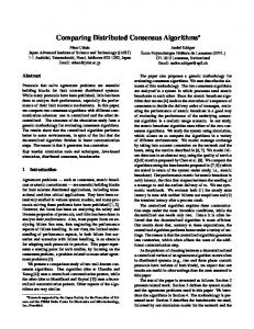
3 Brillouin optical time-domain analysis (BOTDA) This technique takes advantage of the stimulated version of Brillouin scattering, a nonlinear interaction, and is based on a pump-probe technique: an intense pump pulse will interact locally during its propagation with a weak CW probe and the gain experienced by the probe on each location can be analyzed by recording the probe amplitude in the time domain. The frequency difference between pump and probe is scanned step-by-step and the local amplification can be retrieved for a given pump-probe frequency difference. The local gain spectrum can then be reconstructed by analyzing the gain at a given location as a function of frequency, as shown in Fig. 4. The main difficulty is to generate a pump and a probe with a fixed and stable frequency difference of about 10 GHz, with stability typically better than 1 MHz. The first demonstrations used two distinct lasers that were frequency locked using a servo loop [2,3,8]. This is an expensive solution that is subject to instabilities in an adverse environment. Nowadays, most solutions are based on a single laser source that is modulated to make the pump pulses [9]. The light from the same laser is used to synthesize the probe wave by using an electro-optic modulator driven by a microwave signal at the target frequency [5]. The modulator is biased to operate in a suppressed carrier scheme, so that the lower modulation sideband can be used as probe signal (after suppressing the
3
Fig. 4 Principle of data acquisition in a BOTDA system (local amplification is retrieved in time domain and converted into distance units; typical time trace for a pump-probe frequency difference set at 12.800 GHz is highlighted; local gain spectrum at each position can then be reconstructed after a full frequency scan)
upper sideband by optical filtering) [10]. This scheme offers ideal stability since any frequency drift of the laser has no impact on the frequency difference between pump and probe. A scheme of a typical BOTDA system is shown in Fig. 5.
Fig. 5 Block diagram of a typical BOTDA setup
BOTDA setup requires the access to both fiber ends since pump pulse and CW probe must counterpropagate in the sensing fiber. This can be judged as a limitation in some situations. In addition, the electrostriction that stimulates the acoustic wave is driven by the interference between pump and signal, so that their states of polarization must be preferably aligned to create the maximum gain. Orthogonal polarizations will result in a totally vanishing gain, and since the polarization normally varies randomly along an optical fiber [11], a non-zero gain can only be secured using polarization scrambling or a polarization-diversity scheme. This polarization dependence can also be favorably used to efficiently and rapidly measure the local birefringence properties along an optical fiber [12]. The BOTDA is subject to the same limitation as
4
Front. Optoelectron. China
BOTDR for the spatial resolution, i.e., 1 m, limited by the gain spectrum spreading due to the pump spectral broadening for short pulses. This 1 m spatial resolution can be secured up to a distance of 30 km and requires an averaging of less than 1000 to get performances identical to the BOTDR. Figure 6 illustrates the capacity of such a system, showing the local elongation of a short segment of fiber, the raw signal amplification in the time domain for each frequency step, visualized in a three-dimensional (3D) graph, and finally, after processing, the value of the strain as a function of the position. The BOTDA configuration is still under development and is showing constant progress: some solutions are proposed to extend the range and improve the spatial resolution. However, stimulated Brillouin scattering offers the possibility of very innovative schemes and a couple of them will be presented hereafter. The record spatial resolution is currently obtained by a correlation technique proposed in 2000 by Hotate et al. from the University of Tokyo [13,14]. In this elegant alternative technique, the correlation between two continuous lightwaves is controlled. This way, Brillouin scattering can be generated locally along the fiber and the use of a pulsed lightwave is no longer required. Frequency modulation (FM) is the technique that was implemented to create local correlations, and centimetric spatial resolutions can be routinely obtained, however, over a limited distance. Nearly equivalent spatial resolutions can nevertheless be obtained today using pure time-domain techniques over kilometric ranges that will be presented in the following sections.
4
Brillouin echo distributed sensing (BEDS)
The commonly accepted opinion that the spatial resolution of a pulse-based Brillouin sensor is limited to 1 m was seriously questioned when Bao et al. observed an
unexpected narrowing of the Brillouin gain spectrum down to its natural linewidth when pulses turned shorter than the acoustic lifetime (10 ns) [15]. This breakthrough opened the incredible perspective of performing high spatial resolution measurement while maintaining a sharp Brillouin resonance. It is now unanimously accepted by all specialists that this special behavior results from a pre-excitation of the acoustic wave through the presence of a continuous background pump [16]. This was originally observed by using a modulator with a poor off-state extinction ratio to form the pump pulses. Basically, the observation of this effect depends on the pre-existence of an important acoustic wave in the fiber medium vibrating at the exact Brillouin frequency resonance. This acoustic wave is conveniently generated through stimulated Brillouin scattering using a continuous wave at the probe frequency and another continuous wave (or a long pulse) at the pump frequency. Among the three waves involved in the interaction, the two optical waves can experience very fast changes in their amplitude and phase, while the acoustic wave presents a highly inertial behavior and requires a typical time equal to its 10 ns lifetime to adapt to a new situation. For instance, if the pump is suddenly turned off, the acoustic wave will gradually decay and will still exist during the typical duration of its lifetime despite the absence of stimulated interaction. This inertial property is used to change very briefly amplitude or phase of the pump, during a time T so short that the acoustic wave does not experience a notable change (T