[4] H. Soeleman, K. Roy, and B. Paul, âRobust subthreshold logic for ultra-low power ... [10] A. S. Sedra and K. C. Smith, Microelectronic Circuits, 4th ed. Oxford.
Current Sensing Completion Detection for Subthreshold Asynchronous Circuits Omer Can Akgun, Yusuf Leblebici, Eric A. Vittoz Swiss Federal Institute of Technology (EPFL) Microelectronic Systems Laboratory (LSM) Lausanne, CH-1015, Switzerland E-mail:{omercan.akgun, yusuf.leblebici, eric.vittoz}@epfl.ch
Abstract— In this paper a novel completion detection method for self-timed, asynchronous subthreshold circuits is presented. By employing the self-timed operation principle, substantial speed gains in the operation of the asynchronous pipelines can be realized. The completion detection system is very simple, consisting of a sensor transistor, a very basic AC-coupled amplifier and a monostable multivibrator. The proposed method can be easily integrated into the CMOS design flow. The advantages of the proposed completion detection system is shown through simulations on an 16-bit ripple carry adder in a standard 0.18µm CMOS process operating at 400mV supply voltage.
I. I NTRODUCTION Power density and power consumption of complex digital systems has become a major concern during the recent years, both due to thermal concerns and due to limited battery lifetime in mobile applications. Any significant reduction in power dissipation can only be achieved by lowering the operating voltage of the circuits. This would be possible by relaxing the constraints of classical strong-inversion operation of MOSFETs, and by accepting the notion that transistors can (and will) be operated well below threshold, in the subthreshold (weak-inversion) regime. In subthreshold mode of operation, the supply voltage can be scaled aggressively and power dissipation can be decreased significantly. There are successful implementations of digital circuits working in the subthreshold region [1]–[3] and techniques to improve the performance of subthreshold CMOS circuits have also been proposed [4]. Subthreshold operation of static CMOS logic has been analytically analyzed using the EKV model in [5]. According to the analysis, to benefit the most from the subthreshold operation, the logic circuits should be run at their maximum operating frequency with an activity factor α as close to 1 as possible. Maximizing α is non-trivial in synchronous circuits. Because of the fixed time slot for computation, data-dependent processing times cannot be exploited in synchronous operation. Also in a synchronous system, power is consumed with each clock transition regardless of the data or state change. Although clock gating has been proposed as a solution to this problem [6], it cannot provide a comprehensive solution to the problem of data-dependent computation times. On the other hand, asynchronous circuits do not consume clocking power and have the potential of operating with tunable voltage supplies at an α factor of 1 at the optimum supply voltage. In
addition, asynchronous operation also enables the absorption of time-domain (delay) variations that inevitably become more prominent in the subthreshold regime due to the device parameter and temperature variations. Therefore, implementation of efficient asynchronous circuits operating in subthreshold regime would be a subject of high interest. In this work, we demonstrate a novel completion detection system (CDS) for self-timed circuits based on current sensing. The proposed CDS can operate in the subthreshold regime and sense currents in the pA - nA range. The proof of concept is shown by using the proposed system to generate the completion detection signals for an 16-bit ripple carry adder. It has been observed that the improvement in the delay of the overall circuit operation is significant, justifying the use of the CDS. The remainder of the paper is organized as follows. In Section II the basic current equations for MOS transistors operating in the weak inversion regime is given. In Section III the novel CDS is proposed in the context of a 4-phase bundled data pipeline. Section IV shows the application and improvements due to the CDS in terms of the delay of the pipeline stage. II. MOS W EAK I NVERSION O PERATION The MOS digital circuits operate in subthreshold regime when the supply voltage is lower than the threshold voltage (VT ) of the transistors. The drain current of an n-channel MOS transistor operating in this regime is given by [5] IDS = IS exp
VGS − VT nUT
�
1 − exp
−VDS UT
�
(1)
where n is a process dependent term called slope factor and is typically in the range of 1.3−1.5 for modern CMOS processes. The value of n depends on the depletion region characteristics of the transistor. VGS and VDS are the gate to source and drain to source voltages, respectively. The parameter IS is the specific current which is given by, IS = 2nµCox UT2
W L
(2)
where µ is the mobility of carriers, Cox is the gate oxide capacitance per unit area, UT is the thermal voltage whose
Ack
VDD
Acknowledge
Request
Ack
Req C
EN Data
Latch
VDD Low Vt PMOS
A
Delay control
Req
Worst case delay
C
Combinational Logic
EN
Purely Combinational Logic
Combinational Logic
Latch
Fig. 2. Low VT PMOS current sensor used to detect the operation of the combinational block.
(a) Fixed delay implementation Ack Ack
Acknowledge
Request
Delay control
Req C
EN Data
Latch
Computation Dependent Delay
Req C
Purely Combinational Logic
Delay V control
EN
Latch
(b) Computation based delay implementation Fig. 1.
4-phase bundled data pipeline (After [7]).
W L
is the aspect ratio of the value is 26mV at 300K and transistor. Due to the second term in (1), the drain current is 0 when VDS = 0 but reaches its maximum value and saturates with VDS values higher than a few UT . As it is apparent from (1), the drain current of a MOS transistor in subthreshold region shows exponential dependence on the gate-to-source, drain-tosource voltages, slope factor and the operating temperature. To alleviate the problems resulting from the exponential dependence on the supply voltage, process parameters and the operating temperature, self-timed circuits emerge as strong candidates for subthreshold operation. III. C OMPUTATION BASED D ELAY Asynchronous circuits are fundamentally different from their synchronous counterparts. Although the signaling convention is binary, the data propagation through the stages take place by employing handshaking signals, not by using a common clock. A basic 4-phase, bundled data asynchronous pipeline is shown in Fig. 1. In Fig. 1(a) the most common implementation (fixed delay) is shown. In this implementation the Request signal is delayed by an amount equal to the worst case delay of the purely combinational logic stage. This implementation is a similar approach to the synchronous operation, where unnecessary delay, which is fixed regardless of the logic computation time, is introduced. Another version of the 4-phase bundled data pipeline is shown in Fig. 1(b), where the delay should mimic the computation completion time of the logic block as much as possible. In the literature there are examples of completion detection using current sensing methods [8], [9]. The techniques in the mentioned papers use either bipolar transistors, which are not available in standard CMOS processes, or high valued resistors. Although these techniques can be used for detecting
Computation Settling
t
Fig. 3. Computation signature detected as the temporary drop of the supply voltage at the drain node of the current sensor device.
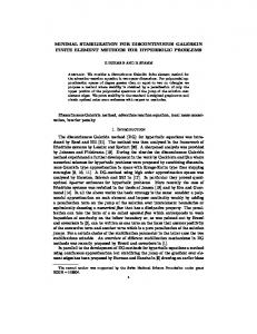
current values in the µA - mA range, they cannot be used for detecting the currents for subthreshold operation which are in the pA - nA range because of the high β requirements of the bipolar transistors and difficulty in implementing very high value resistors. In this paper we propose a new current sensing technique using a single low threshold voltage (VT ) MOS transistor. The basic idea is shown in Fig. 2. In this implementation, the current signal is sensed by the diode connected low VT PMOS transistor, converted to a voltage signal and compressed in the log domain. The conceptual waveform that corresponds to the combinational block processing a new input set is shown in Fig. 3. Two operation regions can be discerned in the figure. One is the time when the actual computation is taking place and the other is the settling of the supply node of the combinational logic block. The settling time depends on the capacitance of the supply node of the logic block and the resistance of the diode connected PMOS transistor. In order to avoid excessive computation delay when compared to the standard implementation, the resistance of the diode connected transistor should be kept as small as possible. The computation time comparison of an 16-bit ripple carry adder with and without the sensor transistor is shown in Fig. 4. In the figure the x-axis shows the computation time of the adder block which is directly connected to the supply voltage and the y-axis shows the computation time of the adder which is connected to the sensor transistor. Each individual data point corresponds to a randomly generated input vector, resulting in a spread of computation (completion) times. As it is apparent from the figure, the adder with the sensor transistor takes about 40% more time for computation, on average.
3.0
VDD
Trigger
n1
n2
n3
2.0
Average computation time increased by 40%.
2.0
2.5
3.0
Fig. 4. Comparison of computation time of the 16bit adder with and without the sensor transistor, where each data point corresponds to a randomly generated input vector. VDD AC Amp & Level shift
Combinational Logic
Fig. 5.
Req
Monostable Multivibrator
Block diagram of the proposed completion detection system.
Trigger
10
15
20
25
30
35
40
25
30
35
40
30
35
40
n1
0.0
The complete CDS consists of the sensing low VT transistor, an AC-coupled amplifier and a monostable multivibrator (Fig. 5). After sensing the current signal and converting to a log-compressed voltage signal, amplification of this signal is necessary before feeding it into the monostable multivibrator. The basic AC-coupled amplifier used for amplification is shown in Fig. 6. Diode connected transistors mp1 and mn1 bias the transistors mp2 and mn2, which are acting as an amplifier, at the maximum gain point for a given size and DC level. By changing the transistor sizes, the frequency response of the amplifier can be changed and there is a trade off between the gain required from the AC-coupled amplifier and the delay caused by the sensor transistor. If greater delay caused by
where R is the average resistance of the PMOS transistor during pulse generation, Ron is the resistance of the NOR gate and Vth is switching threshold of the inverter. Assuming Ron