A chemical-bath treatment that does not form a CdS layer has been used on CIGS absorbers made at the Na- tional Renewable Energy Laboratory (NREL).
Presented at the 29th IEEE PVSC, May 20 - 24, 2002
2P3.15 : Page 1 of 4
INTERFACE PROPERTIES OF CIGS(S)/BUFFER LAYERS FORMED BY THE CdPARTIAL ELECTROLYTE PROCESS 1
1
1
2
2
P.K. Johnson , A.O. Pudov , J.R. Sites , K. Ramanathan , F.S. Hasoon and D.E. Tarrant 1 Department of Physics, Colorado State University, Fort Collins, CO 80523, USA 2 National Renewable Energy Laboratory, Golden, CO 80401,USA 3 Shell Solar Industries, Camarillo, CA 93012, USA
ABSTRACT A chemical-bath treatment that does not form a CdS layer has been used on CIGS absorbers made at the National Renewable Energy Laboratory (NREL). The resultant cells have moderate to high efficiency, with improved current collection at shorter wavelengths. Room temperature quantum efficiency (QE) and capacitance-voltage (CV) results indicate that the different surface treatments yield electro-optical differences in the bulk of the absorber. Room temperature current density-voltage (JV) and AMPS modeling results are used to compare and contrast the results of the surface treatments, primarily from the NREL devices.
INTRODUCTION Thin-film polycrystalline CuInxGa1-xSe2/CdS/ZnO (CIGS) solar cells have been shown to be reliable in the field, relatively low-cost to produce, and have been improving steadily in the past few years. The level of performance achieved by these devices has generated interest in similar devices made without CdS buffer layers. Elimination of the CdS buffer layer has the potential benefits of improved carrier collection in the shorter wavelength portion of the spectrum as well as reduced manufacturing waste. One technique that has had success eliminating the CdS buffer layer essentially diffuses Cd into the CIGS. This is done through the use of a chemical bath similar to that used to deposit CdS, however the sulfur-containing ingredient has been excluded from the bath. This process, referred to as a Cd partial electrolyte (Cd PE) process, has previously yielded working devices with CIS absorber layers [1], and more recently has yielded rather high efficiency (~16%) devices on CIGS [2], as well as devices with respectable efficiency on CuInxGa1-xSeyS2-y (CIGSS) [3]. This paper primarily evaluates devices made from expanding the experiments that yielded the high efficiency CIGS cells. However, brief treatment is also given to the devices fabricated previously, as well as CIGSS devices with absorbers made at Shell solar Industries (SSI). We examine the details of the differences in cell efficiencies resulting from the different surface treatments. We first
3
examine the differences and similarities in AMPS modeling [4] input that yield JV and QE curves qualitatively similar to the two main types of devices (CdS and Cd PE). Next we examine the relative gains and losses in efficiency for the two types of devices using logarithmic JV plots and results from QE measurements. Then we examine the differences in optical reflection between the two devices. Finally, we look at carrier density profiles derived from room-temperature CV. EXPERIMENTAL The CIGS absorbers studied were fabricated using the 3-stage process developed at NREL [5]. Following CIGS deposition, CdS-window devices were made using a chemical bath treatment. Cd PE devices were made using a similar chemical bath treatment, minus the thiourea, and at somewhat elevated temperatures and longer bath times. Details are discussed in another paper at this conference [6]. The devices were completed by sputtering a two-layer ZnO film. The chemical bath conditions for the CIGSS devices referenced here and the earlier CIGS were similar, but had slightly different times and temperatures. Light JV measurements were taken at room temperao 2 ture (25 C) using 100 mW/cm illumination. Dark JV measurements were also taken at room temperature. Quantum efficiency measurements were taken using an Acton Research monochromator to output singlewavelength light, without white light or voltage bias. Reflection measurements were taken using a Perkin Elmer Lambda 2 UV/VIS Spectrometer equipped with a Labsphere Integrating Sphere. AMPS modeling was performed using baseline input provided by the model’s developers, which was then modified to yield JV and QE curves similar to those measured at Colorado State University. Capacitance-voltage measurements were taken using an HP4192A Impedance Analyzer. Prior to measuring CV, capacitance-frequency measurements were taken at room temperature in order to establish the frequency range that yielded good signal separation between the capacitance and conductance signals. A frequency near the middle of this range was used for CV measurements. All measurements were taken on multiple cells on each substrate type and found to be quite consistent across
Presented at the 29th IEEE PVSC, May 20 - 24, 2002
2P3.15 : Page 2 of 4
each substrate. Results from representative devices are shown throughout the text.
less recombination (based on diode quality factors) than most other approaches to p-n junction formation. 40
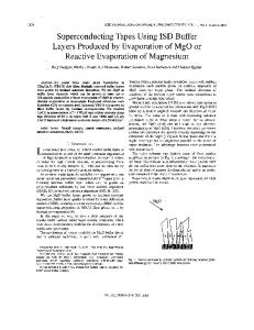
JV results (see Fig. 1) point to similar diode characteristics for the Cd PE and CdS devices; characteristics which are much better than the direct ZnO device with no Cd at all [6]. However, there is sometimes greater crossover between light and dark JV curves in the CdS devices than in the Cd PE devices.
20
0 Cd PE -20 CdS
2
Current Density [mA/cm ]
40
Current Density [mA/cm 2]
RESULTS AND DISCUSSION
20
-40 -0.2 0
Fig. 1. solar cells.
0.0
0.2
0.4
0.6
0.4
0.6
0.8
0.8
Voltage [V] Current density vs. voltage of CIGS-based
Figure 2 consists of JV curves simulated by AMPS-1D for the cells pictured in Fig. 1. The goal of this modeling exercise was to suggest possible mechanisms for differences in the cells rather than finding the exact match to the cells' parameters. Although many of the parameters are similar, the modeled curves have noticeably higher fill factors than the experimental curves. Input to the model consisted of the physical properties of different layers of the cells, as well as the properties of the cell as a whole, which were available to us. Some of the undetermined parameters were used as free variables. Most of the VOC differences seen in Fig. 1, absent a small band gap difference discussed later in the text, were correlated to a factor of three difference in hole density in the modeled absorbers. This is qualitatively consistent with room temperature CV measurements (Fig. 6) in which the higher VOC cell (the CdS cell) has a hole density between 2 and 5 times greater than the Cd PE device. The larger JSC in the Cd PE device was modeled using improved high-energy photon collection due to the absence of CdS in the cell. This difference would have been even larger in the modeled results, had it not been for a higher concentration of deep recombination centers in the absorber. The presence of these recombination centers not only give the model a good qualitative fit to the data, but also a good intuitive fit to real-life expectations, as we have seen many times that CBD CdS yields devices with
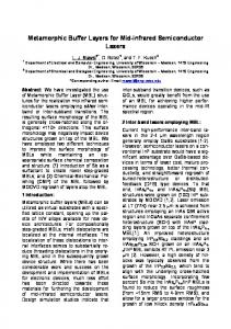
Figure 3 is a plot of internal quantum efficiency vs. wavelength. Note the improved carrier collection in the Cd PE cells at wavelengths less than 520 nm. This is expected, as this correlates with the band gap of CdS. The efficiency gain for the Cd PE device in this case is 2 ~0.6%, due to a JSC gain of 1.3 mA/cm . 100
Cd PE
80 Internal QE [%]
CdS
-40 -0.2
0.2
Voltage [V] Fig. 2. Modeled current density vs. voltage of CIGSbased solar cells.
Cd PE -20
0.0
CdS ∆ JSC = 1.3 mA/cm2
60
=> ∆ η ~ 0.6%
40
= 0.7 ∆ JSC Cd PE # 4 mA/cm
CdS # 6
Cd PE air anneal # 1
=> ∆ η ~ 0.3%
2
∆ Eg ~ 20 meV
20
0 400
500
600
700
800
900 1000 1100
Wavelength [nm]
Fig. 3. Internal quantum efficiency highlighting efficiency differences in the devices due to JSC differences. The Cd PE device also has improved carrier collection at wavelengths above 1000 nm. Although some of this is due to the approximately 20 meV difference in band gap (deduced from QE shown), the CdS cell does have a sharper fall off in this wavelength region. The difference 2 in JSC of 0.7 mA/cm led to an efficiency gain for the Cd PE device on the order of 0.3%. This trend was also seen in the earlier CIGS experiment, and may be due to an improved field-assisted collection. This aspect will be
Presented at the 29th IEEE PVSC, May 20 - 24, 2002
2P3.15 : Page 3 of 4
30
Reflection [%]
25 20
Cd PE 15 10 5
CdS
Eg (ZnO)
0 200
Eg (CdS)
400
600
Eg (CIGS)
800
1000
100 mW/cm2 Room Temperature
A = 1.7 ∆ η ~ 1.7% 80 mV
0.4
0.5
0.6 V - JR [V]
0.7
Fig. 5. Logarithmic current density vs. voltage of CIGSbased solar cells corrected for series resistance and lightinduced collection effects (including shunt resistance). The graphs in Figure 6 contain the results of capacitance-voltage measurements. The inset to figure 6 is the inverse of the capacitance squared as a function of voltage, and contains the results of measurements on eight different cells. Note that the data is clearly split into two groups -- Cd PE cells and CdS cells. Using this data, we calculated the free carrier density as a function of distance from the electrical junction. Two representative hole-density plots are shown in the main portion of Figure 6. In this case, and in other earlier work, the cells without CdS layers have a lower carrier density and hence a wider depletion region than the cells with CdS layers. The larger depletion width may account for an extended field in the absorber, boosting the collection of longer wavelength photons. Also seen in this (not shown) and earlier work are small differences in the carrier density profiles occurring when cells are heated in air typically for five minutes o at 200 C after the chemical bath treatment. The carrier density profiles tend to shift farther away from the junction in these annealed devices. 5 Carrier Density * 1016 [cm-3]
Figure 5 is a semi-logarithmic plot of forward current density, defined as the experimental curve shifted by the short-circuit current density. The plots have also been corrected for series resistance and shunt resistance/lightinduced collection effects. Corrections due to series resistance were quite small and were similar for both devices. The slopes of the lines plotted are fairly similar, but not identical, and hence the relatively small difference in diode quality factors A. Note the approximately 80-mV difference in voltage at the maximum power point. About 20 mV of this difference is due to a slightly higher band gap in the CdS cells. The remaining 60-mV difference accounts for an efficiency difference of approximately 1.7%.
CdS layer A = 2.0
10
1
Wavelength [nm]
Fig. 4. Total reflection of CIGS-based solar cells. Relevant band-gap transitions are shown for reference.
Cd PE
1.0 A2/C2 * 108 [m4/F2]
As seen in Fig. 4, there are noticeable differences between the reflection of the Cd PE devices compared to the CdS devices. The reflection difference is especially prominent between the ZnO and CIGS band gapcorrelated wavelengths, highlighting the major difference between the two device types. The wavelengths corresponding to the band gaps of the solar cell layers of interest have been delineated in this figure. The Cd PE reflection curve has a much cleaner interference pattern in the region between the CIGS and ZnO band gaps resulting almost exclusively from a single (ZnO) interference layer. This observation does not contradict the statement made in the experimental section regarding the ZnO deposition stating that a two-layer ZnO film is deposited, as we assume both ZnO layers are optically similar. The curve for the CdS cell shows a lower average reflection for wavelengths that contribute to the photocurrent, which implies that the CdS layer is helping somewhat with refractive index matching.
100
J + JSC - V/r [mA/cm2]
discussed in greater detail in connection with the CV analysis. The difference in JSC in the mid-range wavelengths has not been examined, as it has not been seen in other iterations of this experiment, and at this time is being treated as an anomaly.
4
3
2
CdS
100 kHz Cd PE
0.5
CdS 75 kHz
0.0
75 kHz -2
-1
0 Voltage [V]
1
Cd PE 0 0.0
0.2
0.4
0.6
0.8
1.0
Distance from Junction [µm]
Fig. 6. Capacitance-voltage results and calculated carrier density as a function of distance from the junction.
Presented at the 29th IEEE PVSC, May 20 - 24, 2002
2P3.15 : Page 4 of 4
We see different patterns in the absorber carrier concentrations in these two device types, which ostensibly differ only in the different baths applied to the exposed CIGS surface. This result is very interesting, as room temperature capacitance-voltage measurements in which the DC bias is varied should be probing the edge of the depletion region furthest from the materials interface (in this case as close as a few tenths of a micron from the materials interface). Thus, we are seeing an effect in the bulk due to a manufacturing difference at the CIGS surface. This leads to the likely conclusion that Cd, a potential n-type dopant that would lower the measured free carrier density, is penetrating, potentially as far as one micron, into the absorber. An alternative possibility is that interactions at the materials interface at the time of junction formation affect the properties in the bulk of the absorber, some distance away from the materials interface, without surface atoms diffusing as far as the effects are observed. We do not have proof of either explanation at this time. However, it is clear from this set of experiments, as well as from earlier experiments, that different surface treatments affect bulk properties of CIGS(S) solar cells.
rier densities demonstrate the effects of the surface treatments away from the metallurgical interface. Thus, we have seen evidence of similarities in device performance coupled with differences in both interface and bulk properties. Ongoing work will investigate the effects of surface treatments on electrical traps measured by admittance spectroscopy.
CONCLUSIONS
[3] P.K. Johnson, et al., "Comparison of Trap States Between CIGSS/CdS/ZnO and Cd PE CIGSS/ZnO Cells", th 17 European PVSEC, Munich, Germany, 2001.
We have seen through a thorough loss analysis, optical assessment, and electrical evaluation that cells made using the Cd PE process have competitive performance to cells made with a CdS layer. The Cd PE devices, in fact, have superior current collection to the traditional CdS devices. Although the resultant efficiency gain is significant, the Cd PE devices lose somewhat more in efficiency than this gain due to inferior voltage. Logarithmic JV plots yielding similar diode quality factors suggest that the current transport mechanisms are fairly similar in both devices. Reflection measurements reinforce the theory that the Cd PE treatment, while integral to forming an effective p-n junction, does not create a layer outside the CIGS. Capacitance-voltage measurements and calculated car-
ACKNOWLEDGEMENTS We thank the members of the U.S. Thin-film Photovoltaic Partnership Program, as their cooperation made this work possible. J. Keane and J. Dolan at NREL contributed expert technical work. NREL Subcontract ADJ-1-30630-06 provided funding. REFERENCES [1] K. Ramanathan, et al., "High Efficiency Thin Film Solar Cells Without Intermediate Buffer Layers", Second WCPEC, Vienna, Austria, 1998, pp. 477-481. [2] K. Ramanathan, et al., to be published.
[4] Analysis of Microelectronic and Photonic Structures (AMPS) software was developed at Pennsylvania State University under the direction of S.J. Fonash with funding from the Electric Power Research Institute. [5] A. Gabor, et al., "High-efficiency CuInxGa1-xSe2 Solar Cells Made from (Inx,Ga1-x)2Se3 Precursor Films", Appl. Phys. Lett. 65, 1994, pp. 198-200. [6] K. Ramanathan et al., "Properties of Cd and Zn Partial Electrolyte Treated CIGS Solar Cells", this Conference.