a PCI bus host adapter for OC-3 and OC-12 ATM, focusing on challenges in ... transmit and receive processing, AAL5 and software-defined. AAL, transmit cell ...
Buffer Management and Flow Control in the Credit Net ATM Host Interface Corey Kosak, David Eckhardt, Todd Mummert, Peter Steenkiste and Allan Fisher School of Computer Science Carnegie Mellon University Pittsburgh, PA 15213 Abstract Among the many benefits of ATM networking are the potential for connections with negotiated quality-of-service (QoS) guarantees and application-specific data management at network endpoints. In this paper we describe the architecture of a PCI bus host adapter for OC-3 and OC-12 ATM, focusing on challenges in the areas of buffer management and flow control, since these are vital to realizing the bandwidth and QoS potential of ATM endpoint hosts.
ATM ASIC
UTOPIA
SONET 155 or 622
SRAM
DRAM
i960 bridge
PCI
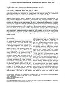
1 Introduction This paper describes the architecture and implementation of the Credit Net ATM host adapter, which provides ATM connectivity at OC-3 and OC-12 rates to hosts with PCI I/O buses. The heart of the Credit Net adapter is an ASIC designed by the Intel Architecture Laboratories, based on an architecture designed jointly with the Credit Net group at Carnegie Mellon University. It provides support for SAR transmit and receive processing, AAL5 and software-defined AAL, transmit cell scheduling, host buffer management, and rate-based and credit-based flow control. The ASIC presents a PCI bus interface to the host and an ATM Forum compliant UTOPIA interface on the network side. The performance goals of the adapter are full duplex operation over an OC-3 155 Mbps link, or half-duplex over an OC-12 622 Mbps link. Internally, the adapter’s bandwidth matches the theoretical peak of the PCI bus, approximately one gigabit per second. The ASIC can be used to build an adapter in two ways. A first adapter architecture consists of the ASIC, memory used to store VC and buffer information, and a physical layer block. OC-3 adapters based on this architecture are operational, and performance results are reported later in the paper. A second version (Figure 1) adds an Intel i960 processor that can be used for experimentation. Specifically, the 960 can be used to experiment with transmit cell scheduling and finegrain, per-VC flow control. An OC-12 adapter based on this This research is sponsored by the Advanced Research Projects Agency under contract number F19628-92-C-0116.
Figure 1: Adapter architecture
architecture is being fabricated at press time. As indicated by its name, the Credit Net adapter has been designed primarily to support credit-based flow control, but it is also well-suited to implement rate-based flow control algorithms, as is discussed later in the paper.
1.1 Challenges The adapter design involved a number of complicated design challenges. Some of these are due to the nature of ATM, and are faced by designers of ATM switches and host adapters alike, while others are particular to the special nature of host endpoints. Among the challenges shared with switch designers are: • The cellular nature of ATM. ATM fragments data into small, fixed-size cells to provide smooth multi-priority multiplexing. Unfortunately, cells on a high-bandwidth ATM link arrive so fast that per-cell decision-making such as routing or accounting must be made every 2.7 microseconds on an OC-3 channel. Hence their implementations must be carefully designed to be practical given current processing technology, and some operations should be delegated to special-purpose hardware. • Flow control. In order to avoid congestion-induced
losses, ATM nodes must engage in some form of flow control. There are many possibilities, ranging in complexity from fixed bandwidth reservations to creditbased or rate-based schemes, either hop-by-hop or endto-end. The more complex schemes promise better bandwidth utilization, but require some per-cell accounting mechanisms. ATM hosts are different from switches in important ways: • Flow control. Since switches handle traffic on many VCs for many hosts, they cannot afford very large perVC buffers. Hosts, on the other hand, can use large communication buffers, easily an order of magnitude larger than switch buffers. In addition, hosts may be employing higher-level flow control methods that decouple the low-level flow control from availability of specific buffers. The mismatch between a host’s packetcentered model of the network and a switch’s cellcentered view also leads to problems. • Host bus I/O is not deterministic. Typically, an adapter will share a host bus with other devices, some of which perform large DMA bursts. In consequence, data arriving from a switch may not be able to move immediately into host memory. Buffer management and flow control solutions must adapt to this. • Host buffer layout is important. Applications have widely differing requirements for buffer size and placement. In order to avoid the overhead of copying, an adapter should provide mechanisms for delivering data appropriately. • Host adapters must perform ATM segmentation and reassembly. This is made especially tricky by the design of AAL5, in which neither the length of a packet nor the location of padding bytes is known until the last cell of the packet has arrived.
1.2 Outline The remainder of this paper is organized as follows. In Section 2 we describe possible buffer management architectures, for both adapter and host buffers, and present our solution. We then discuss flow control in Section 3, focusing on FCVC, which is a credit-based, per-VC, link-by-link flow control scheme[8]. In Section 4 we present the results of our initial experience with the OC-3 adapter, and we conclude in Section 5.
2 Buffer Management A host interface requires the management of two types of buffers. Most memory is shared and managed in cooperation with the host. In addition, a smaller amount of memory on
the network side of the I/O bus is managed by the adapter, to enable real-time access by the adapter independent of competing demands. The host buffers must meet the requirements of diverse applications, such as remote procedure call (RPC), bulk data, real-time data or network management traffic. Applications may want single packets to be composed of areas scattered throughout system memory (for example, headers located in kernel memory and data located in user space), and some applications want tight control over a private memory area. The adapter buffers must support high throughput and low latency, to provide good end-to-end performance. The need to segment and reassemble ATM packets imposes additional requirements. Since two cells received sequentially from a switch may belong to different VCs, the adapter must have a way of quickly switching from one buffer area to another. The adapter’s buffering mechanism must also cope with the possibility that the host I/O bus may be unavailable for multiple cell times if a large DMA burst is in progress. In the remainder of this section, we will discuss application requirements in further detail, present architectural alternatives for adapter and host buffers, describe our architecture, and show how it supports a representative set of applications.
2.1 Application Requirements We would like to support a wide range of applications, differing in how much data they send, whether it is steady or bursty, and how time-critical it is. Applications have two main measures of network efficiency, namely bandwidth and latency. In addition, applications or a whole system may be concerned with the amount of memory that must be dedicated to network I/O to achieve efficient communication. An ATM network link will often run at roughly a substantial fraction of the memory speed of its host, so applicationvisible bandwidth will be severely degraded by accessing or copying data multiple times. The buffer management strategy used by an adapter plays a pivotal role in reducing data access steps[13]. For applications to achieve low latency, their data must be able to bypass less urgent data. While ATM transmission scheduling is an important means of achieving this, low end-to-end latency could be compromised if the host were required to process packets in the order of arrival instead of importance, especially if the urgent packets represent a small fraction of total traffic, as is likely for voice or network management traffic. For these reasons, a network adapter supporting such a range of applications should support the following operations efficiently: • Scatter/gather I/O. For transmit, headers and data will typically be separated in memory, and some applications will have multiple data areas. For receive, some
VCs would like generalized scatter/gather, but important application areas would be content with a system which would assign the first part of a packet to a small buffer and the remainder to one or more large, pagealigned buffers.
host
PCI adapter transfer schedule
DMA
• Autonomous assignment of receive buffers to VCs. Since some applications will have many VCs and not know in advance which ones will be receiving at any time, it would be useful if the adapter could assign buffers to VCs as needed. • Private buffer areas. Some applications need to ensure that only their VCs can use buffers in certain areas of memory. In some cases, such as multimedia traffic, the private buffer area might be in kernel memory, but in other cases it will be in user memory. • Independent notification mechanisms. Low latency for high-priority connections would be difficult to achieve if the host were required to process packets in order of arrival instead of importance, especially since different host entities (kernel, optimized application) may be processing different packets. Section 2.2 describes the main alternatives for buffer organization, and Section 2.3 describes the Credit Net adapter’s buffer architecture. In Section 2.4, we give some examples of how the above features, as provided by the Credit Net adapter, support a variety of applications efficiently.
2.2 Buffer Management Alternatives Recall that an adapter typically has some outboard buffers as well as some buffers shared with the host. We will present design alternatives for the private memory first, because certain adapter architecture choices rule out certain host buffer architectures. 2.2.1 Adapter Buffer Alternatives We considered three designs for private adapter buffers: outboard packet buffering, in which all packets reside in a large memory mapped into the host address space; outboard VC buffering, in which the adapter has one FIFO per active VC; and outboard FIFO, in which the adapter has two short FIFOs to buffer receive and transmit from short bus outages, while all packet buffers reside in host memory. Outboard packet buffering Outboard buffering, as exemplified by the Prototype Nectar adapter[13], the Gigabit Nectar HIPPI adapter[14], or the HP Afterburner adapter[4], assembles and stores all packets in memory located on the adapter (Figure 2). The packets can be mapped into host kernel or user virtual memory, or DMAed into host memory. The main motivations for this scheme are that it is possible to
transmit schedule
packet buffers
segmentation reassembly
packet buffers
Figure 2: Outboard packet buffering
eliminate all data copying, especially if the adapter performs transport-level checksumming, and that the adapter always has immediate access to the memory, eliminating the need for transmit and receive FIFOs. On the other hand, sizing the shared memory is difficult. If the memory is too small, applications will be unable to make use of copy avoidance by sending and receiving directly from their computation memory. If the memory is large, it will represent a significant fraction of the cost of the system, but will not be available for general-purpose use. Another drawback of this approach is that rather than a single point of multiplexing and demultiplexing, it has two (at the entry and exit of the packet buffer); this requires two sets of scheduling and multiplexing protocols, significantly increasing the complexity of the design, and increasing minimum packet latency. Outboard VC buffering If an adapter contains per-VC buffers, as in Figure 3, the segmentation and reassembly processes can be decoupled from the cell by cell operation of the network link. This flexibility accommodates fluctuations in the cell processing times (for example, end-of-packet notification overhead), and makes it possible to buffer across long host bus outages, since high priority cells can bypass other cells. Segmentation and reassembly are done from and to the host’s memory. Like the previous scheme, this requires two sets of scheduling and multiplexing protocols, significantly increasing the complexity of the design, and increasing minimum packet latency. In addition, VC buffers must somehow be sized according to their usage patterns, which could require complicated memory allocation or outboard buffer chaining. Outboard FIFO buffering An adapter without per-VC buffers, as shown in Figure 4, must do segmentation and reassembly of packets directly in host memory. This means that once transmit scheduling decisions are made, the segmentation process must extract cell payloads from system memory and format them for transmission in a strictly ordered pipeline. On the receive side, the adapter can exercise no discretion over the order in which cells are placed in memory, but will do so in the order in which they arrive, i.e. the
host
PCI adapter transfer schedule
transmit schedule
segmentation DMA
VC buffers
reassembly
packet buffers
Figure 3: Outboard VC buffering
host
PCI
adapter transmit schedule
segmentation DMA reassembly
packet buffers
Figure 4: Outboard FIFO buffering
scheduling performed by the output port of the last switch is in effect until cells are placed in host memory. This architecture is the cheapest in terms of on-board memory, and the most flexible way of allocating memory to VCs, but requires that the adapter FIFOs, and hence the worst-case latency added to all cells, can be kept small. 2.2.2 Host Buffer Alternatives Most network adapters are very simple and apply the same buffering strategy to all packets, i.e. there is a single common buffer pool that is used for all data. This makes most data transfer optimizations of the type discussed earlier impossible. ATM naturally supports early demultiplexing: the adapter has ready access to the identity of the VC over which a packet is sent, and can use this information to handle packets in different ways. For example, each logical connection can run over its own private VC, and each open VC can have a sequence of buffers associated with it that are specifically allocated for that logical connection. This would allow applications and protocol stacks to customize the buffer layout for each packet, and optimizations such as header/data split, and application-specific scatter/gather could be easily implemented. Neither of these two extremes, single buffer pool or perVC buffering, is particularly attractive. While a single buffer pool does not support data transfer optimizations, per-VC buffering results in very inefficient buffer utilization. Specifically, since receivers usually don’t know exactly when pack-
ets will arrive, they would have to allocate enough space to store one packet or burst of packets for each open VC. Since hosts can have many open connections, this translates into a commitment of a large amount of buffer space. In reality, only a few of the open connections will be active, i.e. have a packet transfer in progress, at a given point in time. Having the buffering requirements scale with the number of active VCs instead of open VCs would be much more attractive.
2.3 Credit Net Adapter Architecture We now present the architecture of the Credit Net adapter. We chose FIFOs for the adapter buffers, scatter/gather DMA with semi-autonomous assignment for host buffers, and multiple independent interrupt and mailbox channels for host communication. The adapter transmit and receive data paths are simple pipelines, with no VC bypassing capability. Cell transmission is scheduled directly from host buffers, and cells are deposited in host memory in the order they arrive. This architecture is only acceptable if the maximum delay imposed on cells, in this case on all cells, is small. The adapter achieves this by using rapidly-reacting network flow control, described in section 3, and operating the segmentation and reassembly processes at rates that exceed the capacity of the PCI bus, so the potential pipeline management advantages of a VC-buffered adapter are irrelevant. Host buffers are described by 16-byte buffer descriptors which reside in a static RAM on the adapter (the completed OC-3 adapter has 128KB of SRAM, while the OC-12 adapter is designed to have 256 KB). This SRAM area is mapped into the host virtual memory address space for efficient access. Since the SRAM is located on the adapter, buffer management decisions can proceed even when the PCI bus is unavailable. Multiple buffer descriptors may be chained together to provide single-word granularity scatter/gather DMA for a single packet, and each buffer descriptor may be used for transmission or reception at the discretion of the host software. Each outbound VC has a queue of buffer descriptors, which may represent one or many packets. Up to 64K VCs may be active for transmit simultaneously, and data from them is interleaved by a hardware transmit scheduler. As each buffer completes transmission, it is returned to the host via a mailbox, which will be discussed further below. When an incoming VC has data but no currently assigned buffer, the adapter dequeues a buffer descriptor from one of 16 free buffer lists. Associated with each incoming VC are two (possibly identical) free list identifiers. A buffer from the first free list is used to store the first part of the packet, and the remainder of the packet occupies as many buffers as required from the second free list. Host software may reserve free lists for the exclusive use of certain applications or network protocols. For example, a pair of free lists might contain descriptors for small and large buffers residing in a
adapter data structures
1st
rest
host buffers
cur
hdr
body
VC table
pools
buffer descriptors
Figure 5: Receive buffer management data structures
single application’s address space. This would ensure that all data for that application would be received into its address space with no copying. The adapter communicates data-related events to the host via 8 independent mailbox channels. Each mailbox consists of linked list of buffer descriptors in the SRAM and a maskable interrupt generator (these interrupts are ORed together to share a single PCI interrupt). Each mailbox can be programmed to cause a host interrupt for each filled buffer, or for each buffer which represents the end of a packet. Host software may choose to allocate certain mailboxes for special purposes, such as network management traffic, or traffic belonging to a single high-performance application. This means that real-time traffic need not wait while best-effort traffic is processed. Figure 5 shows the data structures used for receive buffer management on the Credit Net adapter. The VC table includes for each VC two free list IDs and a pointer to a buffer descriptor. The buffer can be empty or partially filled. The adapter provides hardware support for AAL5. In particular, it computes the CRC-32 during DMA for transmit and receive, and provides a CRC error indication on receive. On receive, the payload-type bits of the ATM cell header are consulted to determine end-of-packet, which results in a buffer being returned to the host. All AAL5 interface fields are provided to the host as well.
2.4 Adapter Application Support We show how a variety of applications are supported by the Credit Net adapter: • A traditional best-effort network protocol stack, such as BSD Unix, stores data in mbufs and copies data between mbufs and the user’s address space to satisfy the copy semantics of the socket API. Since this protocol stack will typically handle many connections, with ac-
tivity shifting among them dynamically, memory utilization is optimized for at the expense of bandwidth and latency, by using two different buffer sizes: regular mbufs (128 or 256 bytes minus mbuf headers), and clusters (a virtual memory page). Large packets are stored in one or more clusters, while short packets are stored in one or more regular mbufs. This is supported directly on the adapter by using two free lists, one describing host mbufs, and the other describing host cluster mbufs. Large packets will reside in an mbuf and a cluster, while small packets will reside in a single mbuf. The adapter will assign buffers according to demand. • High-performance protocol stacks use copy optimization to eliminate the copy between user space and kernel buffers for large packets. Several techniques can be used to achieve this: use of APIs that have share semantics instead of copy semantics [3, 6, 5], use of outboard buffering to combine the application-kernel copy with the kernel-device copy[14], or use of remapping as a replacement for the application-kernel copy. A common element of all approaches is storing the packet header separately from the data, since the header and data are generated/processed by different entities, namely the protocol stack and the application. This too is directly supported, by specifying one free list of buffers sized for packet headers and one free list specifying virtual memory pages. • Optimized applications that use the ATM network directly, such as distributed scientific computing, database systems, or distributed file systems, will want control over data placement. The requirements can be very simple, e.g. each packet goes in an aligned buffer, or very complicated, e.g. scatter/gather of each packet to allow efficient use by the application [3, 15]. In addition, applications of this type benefit from low per-message overhead because they send small control messages in addition to large data messages. These applications can have private buffer areas and private mailboxes. They can prepare their own buffer descriptors for transmit (though they will need to be verified for safety by the operating system) and can map part of the adapter SRAM to read their own mailboxes. • Network management activities, such as flow control and measuring round-trip and loss rates, take up only a small fraction of link bandwidth, but often require extremely low latency (on the order of a few cell times) to function accurately. This tight latency requirement may mandate private buffer areas and host communication channels, which are supported. • Multimedia traffic, such as voice and video, can obtain guaranteed ownership of a certain amount of buffer
space, preventing blockage by bursts of data traffic that consume all available buffer space.
3 Flow Control In ATM networks, it is very important to minimize cell loss, since the loss of a single cell typically renders the entire PDU useless, usually requiring its retransmission (e.g. [12]). One method for supporting traffic management in ATM networks is to use per-VC flow control. Many variants have been proposed, and they can be organized in two classes. Ratebased schemes [2, 11] propagate information about preferred transmission rates backward along a connection, while in credit-based schemes [8, 10], each node on a VC provides information to the preceding node regarding the availability of buffer space. In either case, the goal is to ensure, with varying degrees of certainty, that cells will be forwarded over a link only when memory is available to store them. In order to provide QoS guarantees, the network must be able to selectively flow control VCs. For example, it must be possible to slow down or stop VCs that exceed their bandwidth contracts while permitting other connections sharing the same network links to proceed at their full rate. Cells on different VCs must be allowed to bypass each other, so that a connection with stopped cells does not prevent progress from being made on other connections. One problem faced by a host credit mechanism that is distinct from the situation on a switch is that bandwidth available to host memory is dynamic due to competing loads. In the extreme case, available I/O bus bandwidth may drop to zero for a period of time if another device engages in a long transaction. In other words, buffer space previously promised, via credit, to the upstream node may disappear for a period of time. To avoid cell loss in this case, the adapter must either provide sufficient onboard buffering for cells arriving during a bus outage, or prevent new cells from arriving. To minimize both buffer hardware and worst-case latencies for high-priority traffic, the Credit Net adapter (along with the corresponding experimental switch) implements a link flow control mechanism, using the ATM GFC header field, whereby a node can stop or start all incoming cell transfers. This lets the switch reorder cells awaiting transmission to the host, allowing high-priority data to bypass other traffic. The need for buffering and consequent latency is thus limited to one round-trip time. Since the mechanism required is easily implemented in low-level hardware, the round-trip time can be kept very close to the speed-of-light limit. This approach overlays, and is compatible with, per-VC flow control methods such as credit or rate control.
3.1 Credit In a credit-based scheme, each node on a VC’s path through the network provides information to the preceding node re-
garding the availability of buffer space. This is achieved by inserting credit information onto the network link traveling in the reverse direction. There is a tradeoff between credit message frequency and switch buffer size–when credit information is received more often, the sender has a more accurate notion of receiver buffer availability, and hence the need for buffer space is be reduced. On the other hand, since credit messages share the link with data traffic, the amount of bandwidth they consume should be kept small. In Credit Net, the overhead of credit cells can be traded off against the amount of memory required to buffer data. It will typically account for approximately 5% of the traffic on a link. The credit round trip time is the amount of time it takes for a credit message to take effect. It accounts for the propagation time of the credit message itself, the time it takes for the sender to react to the credit message, and data cells already in flight by the time the sender reacts. The first and last factors are fixed due to properties of the physical link, but the second is a function of the adapter implementation. Since credit round trip time is a significant factor in determining the size of the switch buffer needed to prevent overflow, an adapter should process credit as rapidly as possible. Another more insidious problem, which we call vanishing credit, is caused by an interaction between buffer management and credit. When assembling AAL5 PDUs, the adapter stores at most one packet per buffer. If the incoming packet is smaller than the buffer it is stored in, the rest of the buffer goes unused. The problem occurs if credit is granted based on buffer size. Since the host cannot typically anticipate the size of incoming PDUs, it may grant credit for a large buffer which is then consumed by a small (e.g. single-cell) packet. In effect, part of the buffer has vanished, leaving the switch with an inflated notion of available buffer space. While many partial solutions exist, such as limiting outstanding credit, revoking vanished credit, using high-level knowledge of packet sizes, etc., no single solution seems appropriate for all applications.
3.2 Implementation In the Credit Net adapter, flow control processing is implemented by an Intel i960 processor on the adapter. This choice was made to provide flexibility for experimental purposes; a hardware implementation is straightforward and would improve efficiency. While most VCs will get their data from or place their data in host memory, it is possible to specify on a per VC basis that the local memory on the adapter should be used instead; this allows the 960 to send and receive data. Flow control processing is implemented by having the 960 handle the VCs that carry the rate-control or credit cells. In this section we first discuss the implementation of creditbased flow control; we then briefly outline one possible implementation of rate-based flow control. There are many variants of credit-based flow control.
They differ in granularity of the credit (incremental [1] or in bursts [7, 8, 9]), the encoding of the credit (absolute or relative), and the buffer management strategy used by the receiver (per-VC buffers, statistical sharing of buffers between VCs, etc.). Credit Net implements per-VC flow control based on the FCVC absolute credit scheme[8]. We briefly explain the algorithm, using the following terminology: for a given VC and network link, data traffic travels from the upstream node to the downstream node, and credit messages travel in the reverse direction. A node can be either a host or a switch. If the downstream node is not a connection endpoint, data traffic will be forwarded by it over a link to another node further downstream; we refer to this outgoing link as the downstream drain. In the basic FCVC N123 scheme, the buffer space reserved per VC by the downstream node has three components: the N1 area prevents overflow by accounting for cells in flight during a credit message roundtrip; its size is proportional to the roundtrip time of the credit message over the link. The N2 area provides buffer space to cover the quantization effect caused by granting credit for a batch of data cells, rather than on a per-cell basis; its size is inversely proportional to the frequency of credit transmission. The N3 area provides sufficient buffer space to prevent underflow on the downstream drain; its size is proportional to that link’s roundtrip time. The N1 area is the one most influenced by host performance, so that will be our focus. There are more sophisticated versions of the flow control scheme that reduce or eliminate N1, at the cost of adding hardware complexity to the sender. Flow control is performed across each link, i.e. switchswitch and switch-host. Although the same protocol is used in either case, there are some differences between the two scenarios that have an impact on how host flow control is implemented. Flow control over the switch-adapter link can be used both to prevent data loss during short-term buffer unavailability (e.g. due to application scheduling on the host), or for endto-end flow control across the network. The former can be addressed by temporarily slowing down less critical VCs by giving them less credit. The latter usage is probably not desirable, as it tends to lead to long-term data storage in the network. This is especially pernicious when the network’s allocation of buffers to VCs is adaptive, as this limits the network’s flexibility and ultimately its throughput.
3.3 Data Transmission (credit processing) The data path from host to switch is similar to the path between two switches: it affects buffer allocation in the downstream switch, and will have to react to congestion in that switch. Since two of the factors influencing the size of the N1 area are credit cell processing time and the reaction time of the transmit scheduler to the new credit, efficient switch
buffer utilization requires that these times are kept as small and as predictable as possible. From an algorithmic standpoint, incoming flow control messages are simple to deal with. The messages are routed to the embedded 960, which interprets the credit cells and updates the data structures used by the transmit scheduler (on ASIC and in 960) to reflect the new credit value. The credit mechanism does not place any restrictions on the scheduling discipline used by the transmitter, except that the transmitter should never send more cells on a VC than it has credit for. The Credit Net adapter’s transmit scheduling mechanism implements this feature.
3.4 Data Reception (credit generation) Flow control for incoming data is potentially more complicated: since the host is at the end of the data pipeline through the network, it is in a position to pace the incoming data flow. This involves making a decision based on the availability of buffer space. On the Credit Net adapter, the 960 sends credit every time a buffer is allocated to a specific VC, i.e. when the buffer is moved from a free list or assigned to the VC by the host. To keep the incoming data pipe full between buffer switches, it is important to account for the delay between when credit is sent out by the 960 and when it takes effect on the upstream node. This is achieved by granting the VC an amount of credit greater than the size of the buffer. The amount of this extra credit is proportional to the roundtrip time between the two nodes. As in real life, overextending credit can lead to problems. If the host’s buffer pool is near exhaustion, the upstream node may send more cells than there is space for, because of the extra credit it has been granted. Extreme cases of the vanishing credit problem can exacerbate this effect. The cells would normally be dropped by the adapter because there is no place to store them. The solution is to carefully monitor the buffer pool size: if it starts to get low, the credit granting algorithm will need to become more stingy with respect to extra credit, perhaps even revoking previously granted credit. This reduces the chance of dropped cells, at the cost of lower throughput. Flow control for host buffers is more complicated in the situation where multiple incoming VCs draw from a common pool of system buffers. In this case, the system needs to provide protection against an application that receives many packets but does not return consumed buffers to the pool. This should not be a problem for applications with correctly functioning end-to-end flow control, but some applications may be less careful. This requires monitoring, at a higher level, of each application’s use of the buffer pool. Again, flow control is a reasonable short-term solution, but it may be most appropriate to simply discard cells addressed to a long-term offender. Accordingly, ATM flow control by the host of data received from the network should be strictly a
3.4.1 Credit handling by the host It is possible to have the credit handling performed on the host processor rather than on an outboard accelerator. This has two ramifications: it incurs additional overhead on the host, and causes longer credit roundtrip times. Since the host can realistically spend only a small percentage of its time managing the network, it will only be able to do credit management in a coarse grain fashion, i.e. take action relatively infrequently compared with a credit engine on the adapter. For the outgoing data stream (host processes incoming credit), this will result in larger buffers on the switch. More buffer space is required to prevent overflow and underflow, because the host will respond more slowly to credit cells. More buffer space is also needed to cover the interval between credit cells, because the host can’t afford to process them as frequently. Our preliminary host credit implementation, for example, examines incoming credit information only when packets are about to be queued for transmission, or when credit messages arrive while VCs are waiting for credit. On a 90 MHz Pentium using OC-3, this processing overhead and occasional credit starvation lead to a decrease in communication throughput of approximately 10%. 3.4.2 Interaction of flow control and buffer management Credit-based flow control opens the door for a new way of doing smart buffer management that can result in copy avoidance. Specifically, for a specific VC, the end point can give out a small amount of credit (corresponding to a header). This will allow the switch to forward the header of a packet (plus possibly a small amount of data) to the host. The host or 960 can then look at the header, do the appropriate buffer allocation, queue the buffer on the VC and grant more credit. This allows exact placement of the data in a potentially data dependent matter and is much more flexible than preallocating buffers for the packet. Another approach that achieves this result is via endto-end interactions: the sender notifies the receiver about what data will be sent, the receiver allocates the appropriate buffers, places them on the VC and then notifies the sender, and the sender transmits the data. The two approaches differ in latency: in the end-to-end scheme, the end-to-end roundtrip time is in the critical path; in the scheme relying on credit-based flow control, it is replaced by the host-switch propagation delay, which is typically substantially shorter. The disadvantage is that network buffers
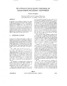
140 120
throughput (Mbps)
short-term measure. A host that cannot provide the network with the expected bus bandwidth or an application that cannot consume packets at the expected rate should expect to lose packets.
100 AAL5 max 80
AAL5 TCP
60
UDP
40 20 0 10
100
1000
10000
100000
size (bytes)
Figure 6: Throughput as a function of packet size (AAL5 and UDP) or read/write size (TCP)
are used, albeit for a limited time, to effectively perform endto-end flow control.
3.5 Rate-Based Flow Control Similar to the credit-based approach, several flavors of ratebased flow control have been proposed. We outline one possible implementation. The implementation of rate-based flow control processing is fairly similar to that for credit-based flow control for the outgoing data stream. Incoming rate consensus cells are routed to, and interpreted by, the 960, which uses the new rate information to modify the maximum rate with which the transmit scheduler will transmit over the VC. The 960 will also periodically generate rate bid cells for each VC. The 960 also handles rate-based flow control processing for the incoming data stream. It must receive and interpret incoming rate bid cells, adjust the rates if they are too high for the host (e.g. because of I/O bus bandwidth limitation), and return rate consensus cells to the network.
4 Performance Figure 6 shows Credit Net adapter throughput between two 133 MHz Pentium PCs with Triton PCI chipsets using raw AAL5, UDP/IP and TCP/IP. For AAL5, throughput is close to the theoretical maximum payload rate, even for relatively small packets. UDP and TCP have lower performance because processing on the host becomes a bottleneck; we expect the performance of these protocols to improve as we tune our preliminary implementations. Note that for small transfers, TCP outperforms UDP due to write coalescing.
5 Conclusion Network adapters for ATM networks are part of the end-toend path between the sending and receive application. As a result, they must participate both in congestion avoidance based on the ATM credit-based or rate-based flow control, and in the implementation of network service guarantees. The organization of the data buffers on the adapter play a central role in both tasks. We showed how a simple FIFO buffer architecture can be used by relying on the switch for appropriate cell scheduling if I/O bus congestion occurs. We also presented a simple architecture for host buffer management that supports copy avoidance, while allowing buffer sharing for less critical VCs. Finally, we discussed the implementation of credit-based and rate-based flow control processing on an ATM adapter. The design we discussed forms the basis for the Credit Net ATM host interface, which connects hosts with PCI I/O buses to OC-3 or OC-12 ATM networks. The OC-3 version of the adapter is currently operational, and the OC-12 version is in fabrication.
Acknowledgments We thank our colleagues at Intel Architecture Laboratories for their vital contributions: Robert Galin, Haim Sadger, Kevin Kahn, Jay Sethuram, Farhad Mighani, Yiftach Tzori, Mark Snesrud and Linda Chen. We thank Prashant Chandra of CMU for assisting with debugging and performance measurement. We also thank past and present Credit Net contributors at Harvard, BNR and HP Labs for many useful discussions.
References [1] T. E. Anderson, S. S. Owicki, J. B. Saxe, and C. P. Thacker. High-speed switch scheduling for local-area networks. ACM Transactions on Computer Systems, 11(4):319–352, November 1993. [2] F. Bonomi and K. Fendick. The rate-based flow control framework for the available bit rate ATM service. IEEE Network Magazine, 9(2):25–39, March/April 1995. [3] J. Brustoloni. Exposed buffering and subdatagram flow control for ATM LANs. In Proceedings of the 19th Conference on Local Computer Networks, pages 324– 334. IEEE, October 1994. [4] C. Dalton, G. Watson, D. Banks, C. Calamvokis, A. Edwards, and J. Lumley. Afterburner. IEEE Network Magazine, 7(4):36–43, July 1993. [5] P. Druschel and L. Peterson. Fbufs: A high-bandwidth cross-domain transfer facility. In Proceedings of the Fourteenth Symposium on Operating System Principles, pages 189–202. ACM, December 1993.
[6] K. Kleinpaste, P. Steenkiste, and B. Zill. Software support for outboard buffering and checksumming. In Proceedings of the SIGCOMM ’95 Symposium on Communications Architectures and Protocols, page To Appear, Boston, August 1995. ACM. [7] H. Kung, T. Blackwell, and A. Chapman. Credit update protocol for flow-controlled ATM networks: Statistical multiplexing and adaptive credit allocation. In Proceedings of the SIGCOMM ’94 Symposium on Communications Architectures and Protocols, pages 101–114. ACM, August 1994. [8] H. Kung and A. Chapman. The FCVC (Flow Controlled Virtual Channels) proposal for ATM networks. In International Conference on Network Protocols, San Francisco, CA, October 1993. IEEE. [9] H. Kung, R. Morris, T. Charuhas, and D. Lin. Use of link-by-link flow control in maximizing ATM performance: Simulation results. In Proceedings of the IEEE Hot Interconnect Symposium ’93, Palo Alto, CA, August 1993. IEEE. ¨ [10] C. Ozveren, R. Simcoe, and G. Varghese. Reliable and efficient hop-by-hop flow control. In Proceedings of the SIGCOMM ’94 Symposium on Communications Architectures and Protocols, pages 89–100, University College, London, UK, October 1994. ACM. [11] K. K. Ramakrishnan and P. Neuman. Integration of rate and credit schemes for ATM flow control. IEEE Network Magazine, 9(2):49–56, March/April 1995. [12] A. Romanow and S. Floyd. Dynamics of TCP traffic over ATM networks. In Proceedings of the SIGCOMM ’94 Symposium on Communications Architectures and Protocols, pages 79–88, University College, London, UK, October 1994. ACM. [13] P. A. Steenkiste. A systematic approach to host interface design for high-speed networks. IEEE Computer, 26(3):47–57, March 1994. [14] P. A. Steenkiste, B. D. Zill, H. Kung, S. J. Schlick, J. Hughes, B. Kowalski, and J. Mullaney. A host interface architecture for high-speed networks. In Proceedings of the 4th IFIP Conference on High Performance Networks, pages A3 1–16, Liege, Belgium, December 1992. IFIP, Elsevier. [15] J. Stichnoth, D. O’Hallaron, and T. Gross. Generating communication for array statements: Design, implementation, and evaluation. Journal of Parallel and Distributed Computing, 21(1):150–159, Apr. 1994.