Our multimedia ISDN PC will support the following applications: Real-time audiohide0 conferencing on ISDN with inte-. Flexible transformations of images ...
Building a Multimedia ISDN PC Michael Jager Technical University Darmstadt
Utz Osterfeld, Hans-Josef Ackermann. and Christoph Homung Fraunhofer Institute for Computer Graphics ~
Our multimedia ISDN PC permits cooperative multimedia work based on real-time video, graphics, and speech. The system relies on a flexible architecture of hardware modules.
nm
ultimedia facilitates the perception of complex information. Since we use it both to present information and to efficiently support human telecommunication, the tendency emerges to connect multimedia workstations to telecommunication networks. Multimedia has the disadvantage of requiring countless system resources to process, store, and transmit data. We could tackle the problem of releasing the CPU from tasks involving the presentation and exchange of multimedia information in several ways. One approach is to extend the system hardware with multimedia devices especially designed for presentation and transmission of multimedia information. More and more, computer manufacturers try to place their products on the multimedia market. However, they focus on particular multimedia domains rather than offering global multimedia solutions. Our approach, presented here, transforms a personal computer into a low-cost multimedia workstation with telecommunication facilities by adding plug-in boards. Since the PC is an open system with a modular architecture, our approach features easy system integration and modular multimedia functionality. The multimedia facilities we developed run under the MSWindows operating system extension. Its multitasking capabilities permit simultaneous execution of both data processing and telecommunication applications. The digital transmission of uncompressed multimedia data requires networks with extremely high transfer rates. While we don’t expect global availability of international broadband networks even in the long run, international standards for the digital network ISDN (introduced by German Telekom in 1989)
24
are currently under preparation. Moreover, since ISDN provides affordable integrated services, commercial subscribers have increasingly come to accept it. One important reason (among others) for the increasing acceptance of ISDN is that users can connect computers directly to the network using ISDN adapters. These adapters allow access to several telecommunication services. The greatest variety of ISDN adapter boards is offered for PCs. To provide for software compatibility among ISDN PC adapters from different manufacturers, a working group, ISDN-PC, was founded under the leadership of German Telekom.
System functionality and archDtecture First let us look at the system requirements, components, and general architecture. Note that the single modules work both alone and as components of the multimedia subsystem-they offer additional features when working together. For example, the video module provides MIP (multum in parvo-many things in a small place) map’ images as textures for the graphics module.
System requirements Our multimedia ISDN PC will support the following applications: Real-time audiohide0 conferencing on ISDN with integrated transfer of application data Flexible transformations of images grabbed by a local camera or disk Flexible transformations of images received via network
0272-17 16/93/o9oo-W24$03.0001993 IEEE
v
IEEE Computer Graphics & Applications
Building a Multimedia ISDN PC
Therefore it fulfils the following technical requirements: Real-time video transfer according to QCIF (a European video format) Temporal conversion to adapt the frequencies of the incoming video and the monitor Spatial conversion to support both affine (translation, scaling, rotation) and perspective image transformation 3D graphics support to integrate and enhance video and graphics To meet these requirements, we proposed a modular architecture.
-ponents Now let us look at the individual components making up our ISDN PC.
TcleconrmunicaCon We designed the system’s telecommunication module to perform audiohide0 communication and data transfer via ISDN. ISDN makes it possible to transmit speech, text, and pictures over a single network. Hence, we have an already established infrastructure for multimedia communication. The ISDN subscriber can choose between two kinds of connection. While basic rate access is designed for direct connection to terminal equipment via its Sointerface, primary rate access is designed for connection to private branch exchanges. Basic rate access offers two B-channels for data transmission and a D-channel for signaling among network nodes. While the B-channels actually perform the data exchange, the D-channel establishes and controls the connection. Each B-channel offers a transmission rate of 64 kilobits per second duplex; the Dchannel can transmit 16 Kbitsls duplex. The S,, interface of the primary rate access offers 30 B-channels and a D-channel with transmission rates of 64 Kbitsls each. Currently, several manufacturers of ISDN adapters offer plug-in boards for different bus systems. The greatest variety of boards exists for the PC AT-bus. Basically,two kinds of ISDN PC adapter boards are available, with significantly different performances. “Active” boards include their own processors, which work out the ISDN protocols. “Passive” boards simply connect the AT-bus to the ISDN interface. Since the boards have no processing power of their own, the CPU must process the ISDN protocols. In the past, the sheer quantity of ISDN PC adapter boards posed a problem: software compatibility between boards. In response, German Telekom and several manufacturers of ISDN PC adapter boards founded the Working Group ISDN-PC in 1989. They developed the Common ISDN Application Programmable Interface (Common ISDN API) as a standardized interface between the telecommunication application program and the protocol software. Since then, the Common ISDN API has become a quasi standard for communication between ap-
September 1993
plications and ISDN PC adapters, and most manufacturers s u p port it. Our ISDN PC has the following functional properties for telecommunication: Line-oriented connection 2 x 64 Kbit full duplex transmission One channel for video, one for audio plus data Standard API for programming (Common ISDN API, or CAPI)
C o n r p r e s d o m ISDN’s transmission rate is insufficient for video communication. To overcome this problem, we need sophisticated compression techniques to reduce the large amount of data required for digital representation of video signals. Since a property of video data is its time dependency, compression must be performed in real time. Hence, we require special hardware solutions to implement compression and decompression (codec) algorithms. Recently, CCITT recommended standards for video coding algorithms applying to 64Kbits/s channels? The first hardware solutions are currently on the market. However, these codecs are realized by means of rather big stand-alone devices and thus are very expensive. For example, German Telekom offers a video telephone for more than 30,000 deutsch marks. Other manufacturers (for example, PictureTel) are currently developing PC-based systems. However, these solutions take the approach of attaching a stand-alone codec to the parallel PC interface rather than integrating it into the PC. This solution has both technical and economicaldrawbacks. The system bus clogs up with piles of uncompressed video data, and the price for a codec is all out of proportion to the price of a PC. Increasing the acceptance of video communication systems requires affordable PC-integrated solutions for video codecs. The compression and decompression component supports several picture formats with a resolution scalablefrom QCIF up to CCIR 601. Compression parameters are strongly related to the picture format to be transmitted. However, in the separate operation mode, pictures are transmitted and displayed in the QCIF format (176 x 144 pixels, 16 grayscales per pixel) with a frame repetition rate of 8 1/3 Hz. To support scalable display size and avoid jerky motions, we must apply spatial and temporal conversion components. Our system has the following functional properties for compression and decompression of images: Support of real-time compression and decompression of QCIF images Flexible adaptation to other image formats up to 768 x 576 Still image coding, supporting single-frame access in compressed video sequences The codec works both alone and in combination with the
25
!
m
.
I
Graphicsfor Telecommunications
Figure 1. Video communication.
Figure 2. Local manipulationof video.
Re moni Camera 1
1
ISDN
’
video module. Consequently, it supports two kinds of video input and output, respectively. The video codec can either receive the analog signal of a standard PAL camera (PAL is a European video standard) or digitized video from the video module. We can present the decompressed video either by direct connection to the VGA device via the feature connector or by transmission to the video module, where a separate graphics module can be attached. Transfer of the compressed video data from the video codec to the ISDN takes place with a commercial ISDN PC adapter board. The video codec’s performance is determined by the realtime requirements of video communication. In the case where we want to transmit QCIF pictures, 8 1/3pictures per second must be compressed and decompressed simultaneously. For the transmission of high-resolution still images, the acceptable time for compression and decompression is not exactly determined. However, given the principles of human interaction, the accepted time for coding and transmission is restricted to a few seconds.
vkko Motion in live video images displayed directly on a graphics monitor appears jerky because of the different sampling rates of video and graphics. NTSC-coded video scenes are sampled at 30 frames per second, while advanced PC monitors, for example, display images at 70 frames per second. The way the frames are generated differs as well. A video frame is generated in two steps, one for each half of the frame (odd and even fields). The frames are joined together by interlacing their rows. Most graphics modes use a full-frame or noninterlaced mode to display the images. These are reasons why uniform motions, sampled in TV norm, seldom appear uniform when displayed on a graphics monitor. To avoid this artifact, we use a technique called “temporal filtering.” Temporal filtering works as a filter between input (video) frame rate and output (graphics) frame rate. It interpolates between different input frames. Consequently, spatial artifacts are replaced by blurring images. To enhance the quality of the video image presentation, we can add more temporal filtering to reduce jerky motions when displaying the video images on a monitor. A digitizer capable of grabbing the video images in TV quality and separating the data paths for transmission and presentation permits better display quality than that transmitted via ISDN. Additional tem-
26
”
Video digitizer t Temporal filtering Spatial
* conversion
,m,+
poral filtering can enhance quality not only of the displayed image but also of the transmitted image. In this case the temporal filtering substitutes temporal subsampling of the video codec module when placed between image digitization and compression. If we do not need real-time transmission, we can send images with original video format to the video codec module for high-quality transmission. Better presentation of video images is also required for additional multimedia functionalities, like high-quality video presentation, real-time video manipulation, and integration of live video images and computer graphics. For this integration (described later), we found a way to handle the video images like a texture. This integration, on-line MIP-map prefiltering, is the application of a known filteringtechnique for still textures in the field of real-time live video texture generation. This prefiltering is also able to replace the subsampling in the video codec module and generates high-quality images in QCIF format. The video module provides the following: Support of standard video formats (PAL, NTSC) in quality up to SVHS Support of output formats up to 768 x 576,50 Hz noninterlaced for the presentation Scaling of the video image by binary factors High-quality generation of video images in QCIF format The video module digitizes the analog video signal and produces a digitalvideo image as the output signal. We can send the output signal to the video codec module, the VGA device, or the graphics module. Figures 1to 4 show the possible signal flows for different placements of the temporal filtering. Figure 2 shows a configuration with local video manipulation. In this case the temporal filtering is used for real-time video manipulation for presentation only. Figure 3 shows manipulation of the video before transmission.In this case two independent sig-
IEEE Computer Graphics & Applications
Building a Multimedia ISDN PC
Figure 3. Manipulationof video before transmission.
Camera I
Video
1
1-
* 4
Figure 4. Manipulationof video after receipt.
Camera
Subsample digitizer
nals, one for presentation and one for transmission, must be generated. Figure 4 shows the configuration with remote video manipulation. In this case the temporal filtering occurs between decompression and display of the receiving PC. It works as a frame rate up-converter to generate the frame rate necessary for display from the frame rate transmitted via ISDN. The performance requirements for temporal filtering demand conversion of rasterized video images’ frame rate to a frame rate that makes it possible to combine the video and the PC’s graphics raster image with a minimum of temporal aliasing. The filtering and MIP-map generation must be done in real time, which means the video module must be able to generate up to 50 MIP-map images per second with a resolution of up to 768 x 576.
Graphics moduk for Spaial conversion Up to this point, we can only display video images in their original aspect ratio and resolution or in the resolutions gained by MIP-map generation. To have the capabilityto zoom a video image or to change its shape in general, we need a spatial conversion unit. Spatial conversion provides the following functions: Arbitrary placement of the resulting video window on the screen. This allows us to drag the video window while live video is still displayed. Scaling of the video image by arbitrary factors. MS-Windows supports the scaling of bitmaps. However, this software function has no real-time capabilities,which we provide through special hardware design. It will be possible to zoom the video window up to the supported full-screen resolution in real time. Mapping of the video image to an arbitrary surface. It will be possible to produce effects like those known from commercials or discussions in TV,such as rotation of the video image with arbitrary angles or mapping the video to a cube, a sphere, or a perspectively distorted quadrilateral (as shown in the art at the beginning of this article). The stand-alone features of the graphics subsystem-like Gouraud shading, alpha blending, and antialiasing-are not the focus of this article, having already been described elsewhere.3To do a spatial conversion, the graphics subsystem receives as input a digitized, preprocessed, live video image derived from the video stage. It produces as output a digitized live video image. The output of the spatial conversion can gen-
September 1993
wl, u
Remote monitor
erally be connected to the display or to the compression unit of the video codec module. The performance of the spatial conversion unit is defined by the requirement of real-time capability. The unit must be able to produce one full-screen image of the maximum supported resolution at the appropriate frame rate.
Systemconfigurations The modules described above can be configured to match different applications, as follows.
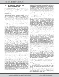
Real-timevkleo colnmunication Support for real-time communication is based on the QCIF frame grabber and the video codec module. The system architecture sketched in Figure l results. Incoming video is grabbed by the QCIF grabber, which subsamples the video image to QCIF format. This image is then compressed by the compression unit and transferred via the ISDN network. On the receiving side, the image is decompressed and displayed in QCIF format via the feature connector of the VGA board.
Local banrfornration of wide0 images Another application area is the local transformation of video images, as shown in Figure 2. The video sequence can be either grabbed or loaded from disk. First the temporal conversion is performed, followed by spatial conversion. The resulting image is then displayed again. T a rof -i before transfer For this application, we preprocess the image before transferring it (see Figure 3). First the image is grabbed. Then it will be temporally adapted (for example, to the resulting 8 1/3 Hz frequency in our application). Moreover, we can perform a spatial conversion. At the end, the resulting image is compressed and transferred via network. The received image is then displayed directly.
27
Graphics for Telecommunications
Figure 5. Functional architecture of the system.
Camera
1
; iv digitizer
I
l s u m e l digitizer
Remote monitor1
Figure 6. Hardware architecturefor video communication.
*-Fl fl Camera
filtering
Subsample digitizer Feature
Buffering connector device Transform
Monitor
\=%+ System bus
monitor
RemoQtranrfonnatknofkcd)ygrabbedinragcs In this application, the image is grabbed and transferred via network. Then, on the receiving side, temporal and spatial c w version are performed and the resulting image is displayed (see Figure 4). Support for real-time communication is based on the QCIF frame grabber and the video codec module.
System architecture Support for all the configurations sketched above requires the overall system architecture shown in Figure 5. The three modules of the multimedia PC correspond to the functions described in the section “Components.” The different architectures of the section “System configurations” are represented in the multiple interconnection possibilities.
Module description Now let us look in detail at the modules.
Coding and transmission We designed the video codec module to provide computersupported telecommunication applications with a multimedia telecommunication channel. The module consists of a PC plugin board that allows-in combination with a commercial ISDN PC adapter board-the transmission of moving and still pictures, speech, and data over ISDN channels. Hence this module’s core function is to enhance PC performance through video and verbal communication. The codec board we developed contains a subsampling digitizer unit and a transform coding unit. The video codec board accepts both digitized video pictures from the video module and analog video signals from a standard PAL camera. The data for presentation of the videos on screen are either transmitted to the VGA device via its feature connector or to the video module. The video codec and the ISDN PC adapter board exchange the compressed video data via the system bus. Figure 6 shows the hardware architecture of the system when working without support of the special video and graphics devices. Data transmission from the PC bus to the ISDNs Sointerface is performed by a commercial ISDN PC adapter board connected to the Sointerface of the ISDN basic rate access. One Bchannel is used for telephoning and the other B-channel simultaneously for the transmission of video data.
28
vkleoCodccbOanl The data rate of a video signal digitized according to CCIR 601 amounts to 216 Mbitsk. To reduce this data stream for transmission via an ISDN B-channel requires a compression rate of more than 3,000. The video codec receives either digitized video data delivered by the video module or an analog video signal delivered by a video camera. In the latter case, a first efficient reduction of video data is achieved by subsampling the video signal during digitization. This subsampling results from applying a special video A/D converter on the video codec board. This video A/D converter runs at a frequency of 3,375 MHz. Consequently, every fourth pixel in a line is sampled. Additionally, only every second line of every third odd half-frame of the interlaced PAL signal is scanned. Hence, with respect to the full PAL video frame, every fourth pixel in every fourth line is sampled. Moreover, only the luminance of each pixel is quantized by four bits per pixel. The resulting video has a spatial resolution of 176 x 144 pixels with 16 gray scales per pixel and a frame repetition rate of 8 113 Hz. This picture format is similar to QCIF, described in CCITT Recommendation H.261.2 After subsampling, the remaining video data rate amounts to 825 Kbits/s, and the compression ratio required for transmission over ISDN is now approximately 13. This remaining compression is achieved by applying still-image compression algorithms similar to the JPEG baseline algorithm4 These algorithms are based on transform coding techniques like discrete cosine transform (DCT), Walsh Haddamard transform, and Karhunen-LoCve transform, which are applied to blocks of 8 x 8 pixels and concentrate the energy of these blocks in a few coefficients of the transform space. This effect is called energy p a ~ k i n gThe . ~ hardware devices usually employed perform the DCT using 8 x 8 blocks of pixels to exploit the redundancy of adjacent pixels. After transformation, the resulting coefficients are quantized. In a following step, the frequency coefficients are zig-zag scanned to rearrange them in linear order with the lowest frequencies first and the highest frequencies last. Next, a selection of coefficients is Huffman coded and then transmitted. De-
IEEE Computer Graphics & Applications
.
I
Building a Multimedia lSDN PC
Figure 7. Block diagram of the video codec board. Buffer 1 Analog videc AID from PAL camera converter
+
compression is performed vice versa. On the video codec board, the JPEG processor, a CL 550, handles transform coding. The CL 550 is a singlechip implementation of the JPEG baseline image compression algorithm. Features inc1u d e
Though we designed the subsampling unit to deliver QCIF pictures, the CL 550 can compress high-resolution color images? In the case of QCIF images, in pure video telephone applications it is sufficient to transmit less than 10 of the lowest frequency coefficients? Selection of these coefficients is performed by appropriate programming of the on-chip quantizer tables. The high processing speed of the CL 550 lets it both compress and decompress the QCIF images simultaneously. This is achieved by toggling the CL 550 between compression and decompression. Hence, after compression of a grabbed picture, a received picture is decompressed and vice versa. The block diagram in Figure 7 shows the signal flow on the video codec board. As described above, subsampling of the analog PAL video signal is performed by the AID converter, which delivers QCIF video. To adapt the QCIF frame rate to the frame rate of the VGA device, buffer 1 and buffer 2 perform double buffering. While a new frame is written into buffer 1, the previously buffered frame is read two or more times from buffer 2 and displayed via the feature connector of the VGA device. When the new frame is completely written, the data input is switched to buffer 2; simultaneously, data output is switched to buffer 1. Now,the new frame is read from buffer 1, whereas the succeeding frame is written to buffer 2, and so forth. We placed a programmable color look-up table between the double buffer and the feature connector. This is necessary to map the 16 gray tones of the QCIF video onto the right entries of the current MS-Windows palette. The CL 550 runs at a frequency of up to 30 MHz. To decouple the different frequencies of the AID converter and the CL 550, a FIFO transmits the subsampled QCIF image to the CL 550. Next, the CL 550 performs raster-to-block conversion of the pixels. Now, each block of pixels is compressed and output
L
v
7
iubsampling l I QCIF from video + module
Real-time compression and decompression of NTSC, PAL, and CCIR 601 video frames Support for several color spaces, like 8-bit grayscale, RGB, YUV, and CMYK User accessible quantizer and Huffman tables DCTIIDCT processor running at up to 35 MHz
September 1993
L
Buffer
*
QCIF to VGA feature connecor look-up -+ or video module table
Color
1L
2
T FIFO
cL-550 Transform coding
to the host bus for transmission to the ISDN PC adapter board. The host-bus interface of the CL 550 was originally designed for connection to Nubus systems. Consequently, we had to adapt it to the AT-bus. The CL 550 receives the compressed video data via the host bus and decompresses it. Then, the decompressed pixels are rearranged from block to raster order and transmitted via FIFO and the programmable color look-up table to the VGA device’s feature connector.
Video The temporal filtering done by the video codec module defines a cycled input picture sequence (read cycle) that is passed to the output. This simple algorithm uses only unchanged picture information from selected input pictures. If the frame rate of the input picture is less than that of the output picture, some or all input pictures must be read out several times. This can produce jerky motions. If the frame rate of the input picture is higher than that of the output picture, the system cannot use all input pictures for the conversion and picture information is lost. To benefit from the low hardware costs of this algorithm, we must accept these disadvantages. To avoid the disadvantages of this approach to temporal filtering, the video module calculates output pictures from all input pictures. The calculation is done by interpolation between the color values of two pixels from two adjacent input pictures. The interpolation is done by weighting the two color values of the pixels with coefficients and adding the results. The values of the coefficients for the interpolation are a function of the temporal distance between an output pixel and the two input pixels from which it must be calculated. The values of the coefficients represent the temporal function of the interpolation, either linear or nonlinear. This algorithm provides a good trade-off between flexibility (it includes the video codec module’s temporal filtering algorithm) and the additional hardware necessary for interpolation. Image quality depends on the algorithm, the image information, and the accuracy of the coefficients. Filtering without in-
29
Graphicsfor Telecommunications
Figure 8. Architectureof the video module.
To
-
telecom module
digitizer
’
-1
1
11
Data
1-
Interpolator
AT-bus
1
Coefficients Temporal filtering controller
double buffer
t
Data to graphics or telecom module
I
Control from graphics module
terpolation or with nonlinear interpolation offers the highest quality if the video includes fast motion of high-contrast moving edges. Linear interpolation offers the best quality with slowmoving edges in the video. The accuracy of the coefficients determines how often per picture the weighting can be adapted. We achieved the best image quality when we adapted the weighting after every row, with good quality if we adapted the weighting after every two to eight rows. The approach we chose to integrate live video in computer graphics consistsof two basic and independent steps. In the first step the video image is prefiltered, and in the second it is mapped like a texture on a surface. The prefiltering is done as a MIP-map, an algorithm known from computer graphics.’ A MIP-map is a representation of an image that offers not only the image with its intrinsicresolution but also filtered versions of the image at lower resolutions. The filtering is done by simply accumulatingthe color values of four adjacent pixels of the higher resolution image and averaging the result to compute one pixel at lower resolution. In this way the size of the different levels of detail, as the filtered images are called, decreases by a factor of four from one level to the next. We would normally do MIP-map filteringof textures for computer graphics off line. We can calculate the exact, position-dependent scale factor for the mapping on line, for example by interpolating between two pixel values of the two nearest levels of detail. To use this algorithm for scaling and manipulating video images, we must calculate a MIP-map image for each video frame. This leads from off-line MIP-map generation, proposed for graphics texture prefiltering, to on-line MIP-map generation for live video images. Using real-time on-line MIP-map prefiltering of video images for easy spatial conversion and video texture generation is new in real-time video manipulation. This algorithm reduces hardware efforts for live video image manipulation in real time
30
and makes it possible to integrate video data and computergenerated graphics. The time to generate an output pixel value from the MIP-map prefiltered image is constant, thus predictable and proportional only to the output image’s size. The absolute time to generate an output pixel depends on the interpolation algorithm between or in the different levels of detail of the MIP-map image. This predictable and fast generation time for an output pixel is important for the integration of video images as video texture in object-oriented graphics generation.
I T I Imodule a u h i i r e The video module digitizes video in TV quality, does the temporal filtering, and generates MIP-map prefiltered images. It connects to the video codec module and the graphicssubsystem. The video module consists of the following units: image digitizer, input triple buffer, interpolator, coefficient buffer, temporal filtering controller, MIP-map controller, and MIP-map double buffer. See Figure 8. The input may be PAL or NTSC coded video, and the output is a MIP-map prefiltered digital raster image of 768 x 576 pixels. The input images are sequentially stored in the input triple buffer. This buffer is necessary not only for interpolation, but also because timing for the camera and the monitor are completely asynchronous. Without the buffer, the asynchronicity would affect the video codec module functions and the use of video as texture for graphics generation. The buffered input framesare passed to the interpolator,which can mix the picture information of two successive frames by interpolating two pixels with identicalframe coordinates.The temporal function of the interpolation,represented by coefficientsfor the pixel weighting, is programmable. Hence, the module supports both algorithms described for temporal filtering. To fully exploit the interpolator’s performance, we also integrated into the video module the on-line MIP-map generation. Presentation requires on-line MIP-map generation of up to 50 frames per second. Scalingthe video images to QCIF format requires generation of only 8 113 frames per second. Description of the units For the image digitizer unit, we chose a chip set from Philips Semiconductorsthat offers high-quality raster image generation and programmable digital color filtering with only a few components. The analog camera signals are digitized, digitally filtered to YUV, and color space converted to RGB. These 768 x 567 raster images are stored in the input triple buffer. For software-controlled initialization, we connect the chip set to the PC’SAT-bus. Because different units write to and read from the input triple buffer asynchronously, it should have independent interfaces for read and write operations. We chose field memory chips from Texas Instruments because they have independent and asynchronous interfaces for read and write operations. Since they work like FIFOs, they do not need address generation. The interpolator consists of special multiplier-accumulator
IEEE Computer Graphics & Applications
Building a Multimedia ISDN PC
chips from TRW LSI Products. The multiplier-accumulator does the interpolation between color values of input pixels stored in the input triple buffer. The coefficients weighting the color values, which present the temporal function for interpolation, are stored in the coefficient memory. The read control signals for the input triple buffer, and the temporal filtering controller generates the addresses for the coefficient memory. The temporal filtered images are stored in the MIP-map double buffer as the first level of detail of the MIP-map image. The other levels of detail are generated successively: The second level of detail is calculated from the first, the third is calculated from the second, and so on. All levels of detail are stored in the MIP-map double buffer. Filtering is done by the interpolator and controlled by the MIP-map generator, which also does the MIP-map double buffer’s address generation.
spatial coIIve!don The MIP-map evaluator must map the video texture, preprocessed by the MIP-map generator, to a surface described in display coordinates forming a 3D space. This is the classical task of a graphicspipeline like that defined by the graphics standard PHIGS+. We manipulate the surface by properly transforming it in 3D space. The surface upon which we want to map the texture is tessellated into triangles. Typically,the surface is a rectangular window, in which case we break the surface down into two triangles covering the area of the rectangle. For a complex case, such as the surface of a sphere, we must approximate the sphere by triangles as well. Depending on the quality required, we might need thousands of trianglesto describe the surface. We must do the geometry calculations for each triangle before our rasterizing hardware can draw the pixels. The burden of processing these triangles lies on the system CPU or a dedicated graphics accelerator. This limits the possible complexity of surfaces or the possible frame rate. To avoid artifacts, we rasterize the triangles using the exact point-sampling technique and subpixel addressing. (Details of the algorithm and it’s hardware implementation are described elsewhere!) Furthermore, we assume that texture addresses are calculated per vertex of a triangle and that the addresses of the area’s other pixels are interpolated in a suitable way. To determine visible surfaces in case of overlapping objects, we apply a z-buffer algorithm. Color values are read from the MIP-map according to the interpolated addresses. The interpolated z-value determines the level(s) of detail. Different possibilities exist to determine the resulting pixel value: The easiest way is to just read one value from one level of detail (point sampling). To increase precision,we can weight up to four values from one map according to the fractional x and y addresses (bilinear interpolation). For higher precision in the z direction, we can interpolate one value from the two nearest levels of detail using weight-
September 1993
ing factors depending on the fractional part of the z address (point sampling, MIP-mapping). The most complex algorithm combines options 2 and 3. In this case we use four values from two different levels to determine the resulting pixel (trilinear interpolation). Scaling and rotation results from manipulating addresses and weighting coefficients. Perspective mapping poses a challenge: For each pixel we must calculate the perspective distance. This requires calculating a quotient per pixel in case of point sampling with only one level of detail involved, and more for complex algorithms. Taking into account that dividing takes a lot of processing time or requires much hardware, we can support perspective mapping in several ways. The easiest is to make perspective interpolation unnecessary. We do this by subdividing the area covered by a triangle in such a way that the range of its z values is small. In this case, the linear approximation of the perspective equation produces no visible artifacts. The drawback is that the unit calculating the triangle addresses is burdened by the higher number of triangles. Another way is to approximate the perspective equation with a quadratic interpolation. This approach avoids division and works better than linear interpolation. The effort required of hardware is moderate. However, significant errors occur in critical cases. Different commercial machines implement this algorithm. A third way is to modify quadratic interpolation. We are working on this approach, which will guarantee the exactness of the perspective equation and require a small amount of additional effort and execution time. The basic idea is to use quadratic interpolation but to subdivide the interpolating curve adaptively so that the resulting errors are invisible. The fourth way is to implement the exact perspective equation. We mentioned the drawbacks of doing this above.
colnponanbofspoltidconverdon The main component of the MIP-map evaluator will be an a p plication-specific IC that rasterizes the trianglesand interpolates the texture pixels according to the algorithms described above. Moreover, the ASIC will be a rendering and shading processor embedded in a graphics system. It will perform Gouraud shading, texture mapping as described above, alpha blending, antialiasing, and dithering. Input primitives will be triangles, meshes, and planar quadrilaterals. Figure 9 shows a block diagram of the system built around the mapperkhader chip. It receives input and command data through the 32-bit input interface. The kind of primitive and length of the data set are coded in the first data word. The interface provides control signals for an external interface FIFO for optimum decoupling.The results of rasterization and mapping are written to the frame buffer. Although 32 bits of color and alpha information are always calculated internally, we can perform realtime dithering to produce eight bits of color information.
31
Graphics for Telecommunications
Data from MIP-map
r accelerator Command host ‘;rmd-H bus I
MIP-map control
’
I
Mapping/ shading engine
FIFO
Figure 9. Architecture of the graphics subsystem.
I
I
Data
4
Frame
-3’ -*
buffer 0
Frame
Control
z-buffer
We assume the frame buffer consists of video RAMS. To achieve sufficient memory bandwidth, we interleaved the memories four times. The maximum size of the frame buffer is 4,096 x 4,096 pixels. To provide invisible redraw of complex graphics images that cannot be generated in real time, the frame buffer can work as a double buffer. The z-buffer interface is similar to the frame buffer interface. Frame buffer and z-buffer connect to a graphics controller providing display refresh, screen clearing, and window management. The most important interface in respect to texture mapping is the texture buffer interface. Because the texture mapping algorithm requires random access, we used static RAM to realize a texture buffer of up to 16 Mbytes. The texture buffer is a double buffer, where one buffer is updated by the MIP-map generation unit, whereas the other stores the MIP-map actually used. The chip calculates the texture address and the interpolations between texture elements. Manipulations like zooming and rotation are implicitly done by transforming the triangles of the mapping surface in the appropriate way before transferring them to the rendering chip. This task should be performed by a floating-point accelerator rather than the system CPU.
lmplementaion Currently, the video codec module works without support from the video module and the graphics module. The video communication function is available through a telecommunication application running under MS-Windows. This program allows us to establish a telephone connection via PC and to send and receive grabbed images. Though the codec’s transform coding unit is still in development, we can currently grab single video frames and transmit them without compression. Temporal filtering is completely implemented and has been tested as an evaluation board. The board consists of standard components and software under MS-DOS. We expect the MIPmap generator to be ready at the end of 1993. A user interface under MS-Windows is under development. We expect to implement all the video module functions in cooperation with the other modules by the end of 1994. We plan to integrate the temporal filtering controller, interpolator, and MIP-map generator as an ASIC. We have evaluated in software the algorithms used by the MIP-map evaluator and realized a simple ASIC version, called Tria (for Triangle Shading Engine), with lower functionality (as described elsewheres). The major goal of a system built with
32
Display controller
T?
buffer 1
coritrol
C P
I I
monitor
this chip has been to provide a graphics subsystem for a PC capable of effectively rendering Gouraud-shaded triangles. The system consists of two major components: A floating-point accelerator module with the Intel i860 boosts transformation and lighting calculation to offload the system CPU. A display module consists of a 2-Mbyte frame buffer controlled by a Texas Instruments TMS34020 processor. The Tria chip attaches to the frame buffer. It boosts rasterization of triangles calculated by the accelerator module. We can use this system for texture mapping as well. With minor changes, the rasterizing algorithm and the linear interpolation part of the Tria chip will be used for the ASIC implementation of the MIP-map evaluator. We have already finished the functional and interface specificationsfor the ASIC. We will now do the design using VHDL for high-level description. The design will be simulated and synthesized using the Synopsys VHDL simulator and silicon compiler. For manufacture of the chip, we will use a 0.7 micron CMOS process. We expect a prototype of the module to be up and running by the middle of 1994. Our integrated PC-based system supports cooperative multimedia work by providing real-time video, graphics, and speech. As explained, at present prototypes of the different modules are under development. We expect to have our first demonstration system, providing real-time codec and video manipulation, by the end of 1993. We expect the whole system to 0 be integrated by the end of 1994.
RekrenceS 1. L. Williams, “Pyramidal Parametrics,” Computer Graphics (Proc. Siggraph83), Vol. 17, No. 3, July 1983,ACM, New York, pp. 1-11. 2. Video Codec for Audiovisual Services a t p x 64 Kbitsls, CCITT Rec. H.261, CDM XV-R 37E, CCITT, Aug. 1990.
3. H.J. Ackermann and C. Homung, “An Architecture for a HighPerformance Rendering Engine,” to appear in Advances in Computer Graphics Hardware VI, A. Kaufman, ed., Springer, Berlin, 1993.
4. JPEG Technical Specification, Joint Photographic Expert Group ISOIIEC,JTCI/SCuWG8, CCITT SGVIII, International Telecommunication Union, Geneva, Aug. 1989. 5. A.K. Jain, “ImageData Compression:A Review,” Proc. IEEE, Vol. 69, No. 3, March 1981,IEEE, Piscataway,N.J., pp. 349-389. 6. C-Cube Microsystems,C-Cube CL550 JPEG Image Compression Processor, Preliminary Data Book, Milpitas, Calif.,Feb. 1992. 7. M. Jager, “Mister Cool: Das multimediale diensteintegrierende ISDN Endgerat,” tech. report GRIS 92-4, J. Encamacao, ed., Forschungs- und Arbeitsbericht, Technische Hochschule Darmstadt, 1992(in German).
IEEE Computer Graphics & Applications
8. H.J. Ackermann and C. Homung, “The Triangle ShadingEngine,”
in Advances in Computer Graphics Hardware V, R.L. Grimsdale and A. Kaufman, eds.,Springer, Berlin, 1992,pp. 3-13.
Michael Jiiger holds a university diploma in telec0”Unication techniques from the Technische Hochschule Darmstadt. Since 1989 he has worked as a research assistant in the Interactive Graphics Systems Group of the Computer Science Department of the Technische Hochschule Darmstadt. Jaeger is concemed with the development of computer-basedmultimedia telecommunication system especially for ISDN. His special interests lie in the area of image compression.
With over 20 years of international experience, Minicomputer Exchange is the leader in used workstations. We stock a large inventory of used and unused SUN, Silicon Graphics and compatible equipment, completely refurbished, tested, warranteed and ready to ship anywhere in the world.
Utz Osterfeld holds a university diploma in telecommunicationtechniques from the Technische Hochschule Darmstadt. Sice 1990 he has worked as a research assistant at the Fraunhofer Institute for Computer Graphics in Darmstadt. Osterfeld is concemed with the development of computer-based real-time video manipulation.
Silicon Graphics Power Series to Personal IRIS
H.a&Josef Ackermann holds a university diploma in computerengineering from the Technische HochschuleDarmstadt. From 1988to 1990 he worked as a researchassistant in the Interactive Graphics Systems Group at the Computer Science Department of the Technische Hochschule Darmstadt. In 1990he moved to the Fraunhofer Institute for Computer Graphics. At present he ent Cooperative and Hypermedia Systems.His field of interest covers graphics hardware in general and high-performance graphicssubsystemsfor PCs. Specifically, he is working on the VLSI realization of a rendering processor.
SUN SERVERS to SLC’s SuperSPARC to Motorola
Our services include: System configuration Equipment rental Emergency repaidexchange In-house technical laboratory Large stock of pretested parts Technical help hot-line Exclusive 120 day warranty Optional extended warrantees Internationalshipment Major savings from manufacturer list price with no compromise of quality
chriptoph Hornung received his university diploma in computerscienceat the University of Saarbrllckenin 1976. He received his PhJ.) in 1984. He has worked several years in industry. Since July 1989 Homung has been head of the department CooperativeHypermediaSystemsat Fraunhofer Institute for Computer Graphics. He is responsible for several projects on cooperative work, multimedia, structural information presentation, distributed rendering, and hardware design for graphicsand video. His major research interests and experiences are in the field of graphicssoftware and hardware, distributedalgorithms,cooperative work, and hypermedia.
For specific pricing on systems, peripherals or boards call, fax, or email
minicommeR excHanGe SINCE 1973
1.408.733*4400
FAX 408.733.8009
email: infoOmce.com 610 N. Pastoria Ave., Sunnyvale CA 94086, USA
Readersmay contact the authors at FraunhoferGesellschaft,Institute for Computer Graphics, Dept. 6 Distributed Hypermedia Systems,Wilhelminenstrase 7, D64283 Darmstadt,Germany.
September 1993 Reder Service Number 2
1