Building a new CTL model checker using Web Services Florin Stoica
Laura Florentina Stoica
Department of Computer Science Faculty of Sciences, “Lucian Blaga” University of Sibiu Sibiu, Romania
[email protected]
Department of Computer Science Faculty of Sciences, “Lucian Blaga” University of Sibiu Sibiu, Romania
[email protected]
Abstract—This Computation Tree Logic (CTL) is widely used to capture compositions of reactive systems. Model checking is particularly well-suited for the automated verification of finitestate systems, both for software and for hardware. A CTL model checker tool allows designers to automatically verify that systems satisfy specifications expressed in the language of CTL logic. In this paper we present a new CTL model checker implemented in client-server paradigm. CTL Designer, the client tool, allows an interactive construction of the CTL models as state-transition graphs. Java and C# APIs are provided for programmatic construction of large models. The server part of our tool embeds the core of the CTL model checker and is published as a Web service. The performance evaluation in terms as speed and scalability was accomplished implementing an algorithm to find a winning strategy in the Tic-Tac-Toe game. Keywords—Model Checking, CTL, Web services
I.
INTRODUCTION
Testing and simulation can give us only confidence in the implementation of a software system, but cannot prove that all bugs have been found. However testing is neither exhaustive nor very effective for software, especially concurrent software, which is much more complex than sequential software. Thus, there has been a tremendous push for efficient algorithms and techniques that allow one to prove that a program satisfies certain properties. The process of stating and proving properties about programs is known as program verification. Verification of a software system involves checking whether the system in question behaves as it was designed to behave. Design validation involves checking whether a system design satisfies the system requirements. Both of these tasks, system verification and design validation can be accomplished thoroughly and reliably using model-based formal methods, such as model checking [17]. Model checking is the formal process through which a given specification representing a desired behavioral property is verified to hold for a given system (the model). Main concern of formal methods in general, and model checking in particular, is helping to design correct systems [1]. In the following we consider that model is a directed graph where the nodes represent the states of the system and the edges represents the state transitions, more specifically a Kripke structure.
The state explosion problem and reducing the time required to verify models are widely agreed to be the most formidable challenges facing the application of model checking to large and complex real-world systems. This naturally raises interest in using parallelism to improve the performance of many formal model checkers. A. Related work Two most common methods of performing model checking are explicit enumeration of states of the model and respectively the use of symbolic methods. Some examples of well-known explicit-state parallel model checkers are DiViNe and PSPIN. DiVinE [1], [2] is a distributed model checker for explicit state LTL (Linear Temporal Logic) model checking and is able to handle large systems consisting of as many as 419 million states, as stated in [3]. PSPIN has also been used for performing distributed model checking with the capability of handling up to around 2.8 million states [13]. The basic idea behind symbolic model checking is to use a more efficient “symbolic” representation for the Kripke structure being checked and for sets of states of the Kripke structure. Since the sizes of these representations is typically the limiting factor in applying model checking, an efficient representation can potentially allow much larger structures to be checked. Symbolic model checkers, such as CadenceSMV [15] and NuSMV [5] analyze the state space symbolically using binary decision diagrams (BDDs), which were introduced in [4]. The binary decision diagram is a data structure for representing Boolean functions. In contrast with explicit-state model checking, states in symbolic model checking are represented implicitly, as a solution to a logical equation. This approach saves space in memory since syntactically small equations can represent comparatively large sets of states [17]. A symbolic model checker represents the Kripke structure itself symbolically using BDDs to represent transition relations by Boolean expressions and perform all calculations directly using these Boolean expressions, rather than using the Kripke structure explicitly. B. Comparing Symbolic and Explicit Model Checking In symbolic model checking, the space used to represent a state is limited by the internal data structures. In explicit model checking, the state size is not strictly limited, but is related with state space size in the total memory consumption. In [8] is
presented a comparison between RULEBASE, a symbolic model checker developed at IBM Haifa Research Laboratory and the explicit LTL model checker SPIN [10]. The software verified was a distributed storage subsystem software application. The state space size handled by SPIN was 108 in a 3-process model. Using symbolic model checking, RULEBASE keeps a compressed representation of the state space and thus was able to manage 10150 states. On the other hand, because of the limit on state size, RULEBASE could not represent a state large enough to include the information needed for more than 2process configuration [8]. Most hardware designs are based on a clocked-approach and thus are synchronous. For these systems, the symbolic model checking approach is more appropriate [14]. On the other hand, for nondeterministic, highlevel models of hardware protocols, it has previously been argued that explicit model checking is better than symbolic model checking [11]; this is because the communication mechanisms inherent in protocols tend to cause the BDDs in symbolic model checking to blow up [3]. In their basic form, symbolic approaches tend to perform poorly on asynchronous models where concurrent interleaving are the main source of explosion, and explicit-state model-checkers have been the preferred approach for such models [3]. A detailed experimental comparison between performance of explicitstate model checkers and symbolic model checkers can be found in [19]. The study follows an automata-theoretic approach in program verification, originally proposed by Vardi and Wolper [20]. Given a program P and a property ϕ, the task is to check whether the program satisfies the property ϕ. If the program P is viewed as a finite-state generator of words, and the specification ϕ as a finite-state acceptor, the modelchecking problem is reduced to an automata-theoretic question: whether the automaton AP ∩ Aϕ is empty. A non-deterministic automaton A defined over a nonempty finite alphabet Σ is said to be universal if it accepts Σ* . The universality problem is to check if A is universal. If AP is a universal automaton, the model checking problem is reduced to check whether Aϕ is also universal. The study presented in [19] uses two approaches, explicit and symbolic, for solving the universality problem. In order to present a full comparison between the symbolic and the explicit algorithms, was performed a scaling comparison of Cadence SMV, NuSMV as symbolic BDDbased model checkers and respectively SPIN. The direct comparison of the three model checkers shows that the explicit one (SPIN) is much faster than the symbolic ones. In conclusion, experimental results show that the explicit approach scales better than the symbolic one, which was rather surprising but confirms similar statements from [3], [11]. C. Motivation and objective The broad goal of our research was to develop a reliable, easy to maintain, scalable model checker tool to improve applicability of CTL (Computation Tree Logic) model checking in design of general-purpose computer software. Concurrent software is asynchronous as the different components might be running on different processors or be interleaved by the scheduler of the operating system. Taking into account the above considerations, in our tool we are using an explicit-state model technique. In order to scaling its
verification ability to handle real-world applications and to address the state explosion problem, our tool is based on an efficient data structure for internal representation of the model to be verified [9]. An orthogonal approach to increase the capacity of an explicit-state model checker tool is to exploit the memory and computational resources of multiple computers in a distributed computing environment [3]. Following this idea, our tool is based on Web Services technology to address the time constraints in verification of large models. The paper is organized as follows. In section 2 are introduced concepts related to the CTL model checking problem: first is defined the CTL model then are presented the CTL syntax and semantics. In section 3 is described the implementation of the CTL model checker in ANTLR. The architecture of the Web service which embeds the server part of our tool is presented in section 4. The performance evaluation of out tool is presented in section 5. Conclusions are presented in section 6. II.
CTL MODEL CHECKING
A temporal logic is essentially an ordinary predicate or propositional logic with the addition of modal operators for describing how the interpretation of symbols changes over time [11]. The CTL logic is interpreted over Kripke structures. CTL logic is branching-time logic, meaning that its formulas are interpreted over all paths beginning in a given state (an initial state) of the Kripke structure. The problem of model checking is to verify if a finite-state abstraction of a reactive system satisfies a temporal-logic specification expressed in the language of CTL logic. A CTL model checker is a tool which verifies that a given system satisfies a given CTL logic formula, using an algorithm that determines the states of a model that satisfy the formula. A. The CTL model A model is defined as a Kripke structure M=(S, Rel, P:S→2AP) where S is a finite sets of states also called nodes, Rel⊆S×S is a transition relation denoting a set of directed edges, and P is a labeling function that defines for each state s ∈ S the set P(s) of all atomic propositions from AP that are valid in s. The transition relation Rel is left-total, i.e., ∀ s ∈ S ∃ s' ∈ S such that (s,s') ∈ Rel. For each s ∈ S, the notation succ(s)={s'∈ S |(s,s')∈Rel} is used to denote the set of successors of s. From definition of Rel, each state from S must have at least one successor, i.e., ∀s∈S, succ(s)≠∅. A path in M is an infinite sequence of states (s0,s1, s2,…) such that ∀i, i≥0, we have (si,si+1)∈Rel. We use s' ∈ succ(s) to denote that there is a relation (s, s') in Rel. The labeling function P maps for each state s ∈ S the set P(s) of all atomic propositions from AP that are valid in s [12]. A CTL formula has the following syntax:
ϕ :: true|false|ap|(¬ ϕ1)| ϕ1∧ϕ2| ϕ1∨ϕ2| ϕ1⇒ ϕ2| AX ϕ1| EX ϕ1| AG ϕ1| EG ϕ1| AF ϕ1| EF ϕ1|ϕ1AUϕ2| ϕ1EUϕ2, ∀ap∈AP. The CTL syntax include several operators for describing temporal properties of systems: A (for all paths), E (there is a path), X (at the next state), F (in future), G (always) and U (until). A CTL formula encodes properties that can occur
along a particular temporal path as well as to the set of all possible paths. The set of all paths through a Kripke structure is assumed to correspond to the set of all possible computations of a system. B. Fixed-point characterization of CTL Let M=(S, Rel, P:S→2AP) be an arbitrary finite Kripke structure. Given a state s in S, is defined a satisfaction relation (M, s) ⊨ ϕ to specify that formula ϕ holds in s. We denote by ⟦ϕ⟧M = {s∈S | (M, s) ⊨ ϕ} the set of all states from S which satisfy the formula ϕ (the set of states at which ϕ is true). ⟦ϕ⟧M is called the denotation of ϕ in model M. Because often M is implicit, we write ⟦ϕ⟧ rather than ⟦ϕ⟧M . Thus (M, s) ⊨ ϕ ⇔ s ∈⟦ϕ⟧. In the following 2S is used to denote the power set of the set S. Let f : 2S →2S be a set valued function and Z ⊆ S a subset of S. Z is called a fixed point of f if f (Z ) = Z. Z is called the least fixed point (LFP) of f if f (Z ) = Z and ∀ U ⊆ S, f (U ) = U ⇒ Z ⊆ U. Z is called the greatest fixed point (GFP) of f if f (Z ) = Z and ∀ U ⊆ S, f (U ) = U ⇒ U ⊆ Z. The universal and existential pre∀, pre∃ : 2S →2S are defined by:
pre-image
functions
pre∀(X) = { s∈S | succ(s) ⊆ X} pre∃(X) = { s∈S | succ(s) ∩ X ≠ ∅}
(1)
For a CTL formula ϕ, the model checker will compute ⟦ϕ⟧ recursively, using the rules described in the following table, where LFP and GFP represent the least fixed point and respectively the greatest fixed point of the specified functions. The algorithm for effective computation of ⟦EF ϕ⟧ is presented in the following section. TABLE I. RECURSIVELY COMPUTATION OF DENOTATION ⟦ϕ⟧ OF CTL FORMULA ϕ. Formula ϕ ap true (false) ¬ ϕ1 ϕ1∧ϕ2, ϕ1∨ϕ2 AX ϕ1, EX ϕ1 ϕ1 AU ϕ2 ϕ1 EU ϕ2 AG ϕ1 EG ϕ1 AF ϕ1 EF ϕ1
III.
Computation of ⟦ϕ⟧ { s ∈ S | ap ∈P(s) } S (∅) S \ ⟦ϕ1⟧ ⟦ϕ1⟧ ∩ ⟦ϕ2⟧, resp. ⟦ϕ1⟧ ∪ ⟦ϕ2⟧ pre∀(⟦ϕ1⟧), resp. pre∃(⟦ϕ1⟧) LFP of f(X) = ⟦ϕ2⟧ ∪(⟦ϕ1⟧ ∩ pre∀(X)) LFP of f(X) = ⟦ϕ2⟧ ∪(⟦ϕ1⟧ ∩ pre∃(X)) GFP of f(X) = ⟦ϕ1⟧ ∩ pre∀(X) GFP of f(X) = ⟦ϕ1⟧ ∩ pre∃(X) LFP of f(X) = ⟦ϕ1⟧ ∪ pre∀(X) LFP of f(X) = ⟦ϕ1⟧ ∪ pre∃(X)
IMPLEMENTATION OF A MODEL CHECKER IN ANTLR
The CTL model checker is provided as a compiler C:Ls→Lt, where Ls is the source language and Lt is the target language. The source language Ls is the language describing the CTL formulas and the target language Lt is a language which describes the set of nodes from the model M where the corresponding CTL formulas are satisfied. The compiler C translates a formula ϕ of the CTL model to the set of nodes ⟦ϕ⟧ over which formula ϕ is satisfied. That is, C (ϕ)=⟦ϕ⟧ where
⟦ϕ⟧={s∈S| (M,s) ⊨ ϕ}. The implementation of the compiler C is made in two steps. First, we need a syntactic parser to verify the syntactic correctness of a given formula ϕ. Then, we should deal with the semantics of the CTL language, respectively with the implementation of the CTL operators presented in Table I. Writing a translator for certain language is difficult to be achieved, requiring time and a considerable effort [18]. For implementation of the algebraic compiler we choose the ANTLR (Another Tool for Language Recognition). ANTLR [16] is a compiler generator which takes as input a grammar an exact description of the source language, and generates a recognizer for the language defined by the grammar. In order to translate a formula ϕ of a CTL model to the set of nodes ⟦ϕ⟧ over which formula ϕ is satisfied, is necessary to attach actions to grammatical constructions within specification grammar of CTL. The actions are written in target language of the generated parser (in our case, Java). These actions are incorporated in source code of the parser and are activated whenever the parser recognizes a valid syntactic construction in the translated CTL formula. In case of our compiler C, the actions define the semantics of the CTL model checker, i.e., the implementation of the CTL operators. The model checker generated by ANTLR from our specification grammar of CTL takes as input the model M (where are defined the sets S, Rel, and P) and a formula ϕ, and provides as output the denotation of ϕ – the set of states where the formula ϕ is satisfied, using an algorithm which handles temporal operators AX, EX by computing pre-images using expressions given in (1) and implements the temporal operators AG, EG, AF, EF, AU, EU by applying rules described in Table I, until a fixpoint is reached. The algorithm for computing ⟦EF ϕ⟧ is presented in Fig. 1 [6]. For the formal specification of the EF operator given in Fig. 1, the corresponding action included in our ANTLR grammar of CTL language is detailed in Fig. 2, where PreExist() represents the implementation of function pre∃(X) described in equation (1). Z:=S; Z':= ⟦ϕ⟧; while (Z≠Z') do Z:=Z'; Z':=Z'∪ pre∃(Z'); endwhile ⟦EF ϕ⟧:=Z'; Fig. 1. Formal definition of the set expression ⟦EF ϕ⟧. ctlFormula returns [HashSet set] @init { } : 'ef' e=implExpr { HashSet rez = new HashSet(all_setS); HashSet rez1 = new HashSet($e.set); while (!rez.equals(rez1)) { rez.clear(); rez.addAll(rez1); HashSet tmp = PreExist(rez1); rez1.addAll(tmp); } $set = rez1; } Fig. 2. Implementation of the EF operator in ANTLR
Analogue were implemented all CTL temporal operators. For efficient representation of CTL models, our tool is based on SingleGraph class from GraphStream package [9].
IV.
ARCHITECTURE OF THE CTL MODEL CHECKER TOOL
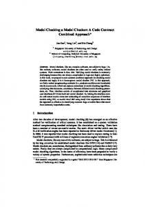
The system architecture of the CTL model checker tool is depicted in the following UML package diagram:
Fig. 3. The system architecture of the CTL model checker tool.
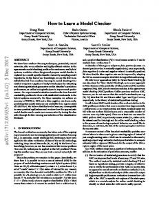
The CTL model checker tool contains the following packages: • The algebraic compiler (CTL Compiler) embedded into the Web Service (CTL Checker). • The GUI client application written in C# and used for interactive construction of the CTL models as directed graphs (CTL Designer). • The CTL non-GUI model package contains classes used for internal representation of a CTL model as a directed graph. There are available two libraries, for C# and respectively for Java. For internal representation of a CTL model in C#, our implementation is based on data structures provided by [7], more precisely symmetrically stored forward and backward adjacency lists. The Java implementation is based on GraphStream [9]. • The XML API for CTL models package contains classes needed to encode the CTL model into XML. • The CTL GUI Model package is responsible with graphical representation of the Kripke structures as directed graphs. We choose to publish our implementation of CTL model checker as a Web service in order to utilize the combined resources of distributed computers and to bring advantages of distributed verification to various clients over the Web. For a better understanding of the CTL model checking process, in Fig. 4 is represented the Use Case Diagram of our model checker. The Web service will receive from a client the XML representation of a CTL model M and a CTL formula ϕ to be verified. The original form of the CTL model M is then reconstructed and passed to the algebraic compiler C generated by ANTLR using our CTL extended grammar. For a syntactically correct formula ϕ, the compiler will return as result C(ϕ)={s∈ S | s ⊨ ϕ}, the set of states in which the formula is satisfied. If as input is an erroneous formula ϕ, the model checker will return to client an message describing the error. In our tool is enabled a compression facility for large CTL models, to reduce the network traffic between client and server. Our Web service is using GlassFish or Tomcat as a Web container. For testing purposes, the CTL model checker described in this paper is available online via two Web services hosted by use-it.ro and respectively by mcheckuseit.rhcloud.com.
Fig. 4. The Use Case Diagram of the CTL model checker
V.
PERFORMANCE EVALUATION OF OUR TOOL
In this section we describe the usage of our model-checker to design a game strategy when playing Tic-Tac-Toe (called TTT for short in the rest of this paper). First, let us describe the (classical) game of Tic-Tac-Toe. The game is played by two opponents, X and O, with a turn-based modality on a 3×3 board. The two players take turns to put pieces on the board. A single piece is put for each turn and a piece once put does not move. A player wins the game by first lining three of his or her pieces in a straight line, no matter horizontal, vertical or diagonal. If the entire board becomes full but no player has formed a line, the result is a draw. In our example, player X is played by the application and player O should be played by a human. CTL model checking algorithm is used to return a strategy to achieve a winning strategy for the computer. The TTT is a turn-based synchronous game. In such a system, at every transition there is just one agent that is permitted to make a choice (and hence determine the future). In the following we will show how to use the CTL formalizations in finding winning strategies in case of TTT game. A. Modelling the Game We suppose that positions Fig. 5: 0 3 6
of the board are numbered as in 1 4 7
2 5 8
Fig. 5. Labeling the grids on the board
Values of the board locations are denoted by xi ∈ {0,1,2}, where i ∈ {0,1,...,8}. The value 0 means an empty position, the value 1 denotes a previous move of the player X and the value 2 represents a move of the player O. For the sequence of values xl xm xn we define:
∑x x
x = min( xl ,1) + min( xm ,1) + min( xn ,1)
l m n
where l , m, n ∈ {0,1,...,8} . Formally, the Kripke model of TTT is defined as M = (S, Rel, P:S→2AP) with its structure explained in the following. The set of atomic propositions AP is denoted by:
CTL model checker tool can be downloaded from http://useit.ro.
AP = {( xl xl +1 xl +2 l =0,3,6 , xl xl +3 xl +6 l =0,1,2 , x0 x4 x8 , x2 x4 x6 , T ) | xk ∈ {0,1, 2} for k = 0,8 and
T ∈ {1, 2} }. The number of successors of a state is given by the formula: 9−
∑ xx
l = 0,3,6
l l +1 xl + 2
l l +1 xl + 2
[1]
. [2]
A state labeled with value T =1 signify that is turn of the player X for making the move and if T =2 then the player O will make the next move. The game stops (so no moves are possible) if the board moves locations are full, i.e.:
∑ xx
REFERENCES
[3]
=9
l = 0,3,6
Another situation where the game is not continuing is when a player won. The state s is a winning state for player X if 111∈ P ( s ) and it is a winning state for player O if 222∈ P ( s ) . Alternation to move can be formalized as follows: for a transition ( s, s ') ∈ Rel , there are the following cases: T ∈ P ( s ) ⇒ 3 − T ∈ P ( s ') where T ∈ {1, 2} . Assuming that the game is in the state s0 ∈ S, we denote by k the number of empty positions of the board. The winning strategy of player X aims to determine all states from the model satisfying the formula: (AX EX)k/2(AX 111 ), to choose the move which favors wining of the game in the future.
[4] [5]
[6]
[7]
[8]
[9]
B. Experimental results Although the game implemented is relatively simple, due to the large size of the structure representing the CTL model at the first moves, it represents a good opportunity to study the effectiveness of our approach in designing and implementing a CTL model checker. In the Table II are presented the results showing the performance of the CTL model checker when running on Intel Core I5, 2.5 GHz, 4Gb RAM to find a winning strategy for Tic-Tac-Toe game. TABLE II. EVALUATING THE PERFORMANCE OF THE CTL MODEL
[10] [11] [12] [13]
[14]
CHECKER
States Time(sec)
2236 0.13
2307 0.14
2425 0.16
VI.
3423 0.3
3683 0.32
3732 0.35
4255 0.43
4791 0.6
CONCLUSIONS
In this paper was presented a new CTL model checking tool, based on client/server architecture. In contrast to previous approaches, our tool permits an interactive design of the CTL models as state-transition graphs, and is based on client/server architecture. The implementation of the CTL model checking algorithm is based on Java code generated by ANTLR using an original grammar for the language of CTL formulas, having semantic actions attached to production rules. Programmatic construction of large models is supported through two libraries (C# and Java). The server part of our tool was published as a Web service and is available online at two Internet locations, use-it.ro and mcheck-useit.rhcloud.com. All components of our
[15]
[16] [17] [18] [19]
[20]
Barnat, J., Brim, L., Ročkai, P., 2010. “Scalable Shared Memory LTL Model Checking”. International Journal on Software Tools for Technology Transfer (STTT), 12(2):139-153. Barnat, J., Brim, L., Češka, M., Ročkai, P., 2010. “DiVinE: Parallel Distributed Model Checker (Tool paper)”. In Parallel and Distributed Methods in Verification and High Performance Computational Systems Biology (HiBi/PDMC), pp. 4-7. IEEE. Bingham, Brad, Bingham, Jesse, M. de Paula, Flavio, Erickson, John, Singh, Gaurav, Reitblatt, Mark, 2010. “Industrial Strength Distributed Explicit State Model Checking”. In Proceedings of the 2010 Ninth International Workshop on Parallel and Distributed Methods in Verification, and Second International Workshop on High Performance Computational Systems Biology (PDMC-HIBI '10). IEEE Computer Society, Washington, DC, USA, pp 28-36. Bryant, Randal E., 1986. “Graph-based algorithms for boolean function manipulation”. IEEE Transactions on Computers, C-35(8):677-691. Cimatti, A., Clarke, E., Giunchiglia, F., Roveri, M., 2002. “NuSMV: a new symbolic model checker”. STTT International Journal on Software Tools for Technology Transfer. Springer Verlag, pp. 410–425. Clarke, E., Grumberg, O., Long, D., 1996. “Model checking”, In M. Broy, Deductive Program Design, NATO ASI Series F, vol. 152, Springer Verlag. Ebert, J., 1987. “A Versatile Data Structure for Edge-Oriented Graph Algorithms”, Communications of the ACM, Volume 30, Number 6, pp. 513-519. Eisner, Cindy, Peled, Doron, 2002. “Comparing Symbolic and Explicit Model Checking of a Software System”, In Proc. SPIN Workshop on Model Checking of Software, volume 2318 of LNCS, Volume 55, pp. 230-239. GraphStream, 2012. A Dynamic Graph Library, http://graphstreamproject.org/ Holzmann, G., 1997. “The model checker SPIN”. IEEE Trans. on Software Engineering 23, pp. 279–295. Hu, A. J., 1995. Techniques for Efficient Formal Verification Using Binary Decision Diagrams, PhD thesis, Stanford University. Huth, M., Ryan, M., 2000. “Logic in Computer Science: Modelling and Reasoning about Systems”, Cambridge University Press. Lerda, F., Sisto, R., 1999. “Distributed-memory model checking with SPIN”. In Proc. of SPIN 1999, volume 1680 of LNCS. Springer-Verlag, 1999, pp. 22–39. Lerda, Flavio, Sinha, Nishant, Theobald, Michael, 2003. “Symbolic Model Checking of Software”, Electronic Notes in Theoretical Computer Science, Volume 89, Issue 3, pp. 480–498. Mir, Ali Abbas, 2000. Subhashini Balakrishnan and Sofine Tahar. “Modeling and Verification of Embedded Systems using Cadence SMV”. Conference on Electrical and Computer Engineering, 2000 Canadian, Vol. 1, pp. 179–183. Parr, Terence, 2007. The Definitive ANTLR Reference, Building Domain-Specific Languages, version: 2007. Rozier, K.Y., 2011. “Survey: Linear Temporal Logic Symbolic Model Checking”, Computer Science Review, Volume 5 Issue 2, pp. 163-203. Rus, T., 1991. “Algebraic construction of computers”. Theoretical Computer Science, Vol 90, pp. 271-308. Tabakov, Deian, 2005. Experimental Evaluation of Explicit and Symbolic Automata-Theoretic Algorithms, Master of Science thesis, Rice University, Texas. Vardi, M.Y., Wolper, P., 1986. “An automata-theoretic approach to automatic program verification”. In Proc. 1st Symp. on Logic in Computer Science, pages 332-344, Cambridge.J. Clerk Maxwell, A Treatise on Electricity and Magnetism, 3rd ed., vol. 2. Oxford: Clarendon, 1892, pp.68-73.