DAC 2003, June 2â6, 2003, Anaheim, California, USA. Copyright 2003 ... cation language, the TLC model checker, the EV7 multi- ... ification Framework. TLA. +.
23.1
Using a Formal Specification and a Model Checker to Monitor and Direct Simulation ∗
Serdar Tasiran Koc¸ University Istanbul, Turkey
Yuan Yu
Brannon Batson
Microsoft Research Mountain View, CA
Intel Corporation Santa Clara, CA
ABSTRACT
is written to check for violations of the high-level specification during simulation. This approach is inadequate for several reasons. First, since the specification is informal, it is difficult to verify whether it is consistent and complete. Second, the code checking for specification violations may itself contain errors. Third, and most important, it is difficult to quantify how well different aspects of the specification have been explored, and to direct simulation runs towards unexplored areas. We present a technique that improves this process. Our technique requires a high-level specification written in a formal language and a mapping that relates simulation steps in the implementation to state transitions in the specification. A model checker checks each such state transition for consistency with the formal specification, and collects coverage information using the specification states visited. Gaps in coverage, deadlocks, assertion and invariant violations at the specification level can all be formulated as target states for the model checker, which is then used to generate traces to these target states. These traces provide very useful starting points for generating implementation level simulation runs to exercise the protocol scenario under consideration. It is difficult to automate this final step, nevertheless, the problem of simulation input generation is greatly eased when a possible error scenario is provided in the form of a protocollevel trace. Our approach provides several significant benefits:
We describe a technique for verifying that a hardware design correctly implements a protocol-level formal specification. Simulation steps are translated to protocol state transitions using a refinement map and then verified against the specification using a model checker. On the specification state space, the model checker collects coverage information and identifies states violating certain properties. It then generates protocol-level traces to these coverage gaps and error states. This technique was applied to the multiprocessing hardware of the Alpha 21364 microprocessor and the cache coherence protocol. We were able to generate an error trace which exercised a bug in the implementation that had not been discovered before a prototype was built.
Categories and Subject Descriptors M.1.5 [Design Methods]: Design Methodologies—Functional design verification; T.2.2 [Design Tools]: Design Verification—Functional Semi-formal Verification
General Terms Verification, Design
Keywords Specification, abstraction, coverage, model checking
1.
• Using formal verification techniques, inconsistencies and other logical errors can be eliminated from the specification and it can be ensured that the specification is complete. [1, 7] • Each step of the simulation is checked against a verified, protocol-level specification using a formal verification tool. Formal verification tools are better debugged than design- and protocol-specific code. • A discrepancy of the implementation from the protocol design is signaled as soon as it occurs, where its cause can be pinpointed easily. • Coverage analysis based on the specification points out gaps in validation. We measure state coverage for a subset of specification variables and report unexplored assignments to these variables. • The counterexample generation facility of model checkers is used to facilitate simulation input generation to address gaps in specification coverage.
INTRODUCTION
For hardware implementing a complex protocol, verification of consistency with high-level specifications is a labor intensive process that is never entirely completed in practice. Simulation using random patterns or hand-written test programs is the only tool available for this validation task. Typically, the design is written in a hardware description language and the specification is a text document. Code ∗This work was done while the author was with the Systems Research Center at Compaq (now HP).
Permission to make digital or hard copies of all or part of this work for personal or classroom use is granted without fee provided that copies are not made or distributed for profit or commercial advantage and that copies bear this notice and the full citation on the first page. To copy otherwise, to republish, to post on servers or to redistribute to lists, requires prior specific permission and/or a fee. DAC 2003, June 2–6, 2003, Anaheim, California, USA. Copyright 2003 ACM 1-58113-688-9/03.0006 ...$5.00.
The price paid for these benefits is the effort put into constructing an abstraction map. To ease this task, we present
356
s is visited while exploring the state-space, instead of storing the entire set of variable assignments that define s, TLC stores v (s) and, in this way, visits only one state for each value in the range of v . v can be used to define a coverage metric on the specification state-space by assigning the same value of v to states that are qualitatively the same. A further reduction in the number of states explored is achieved by exploiting the fact that the EV7 protocol specification is symmetric with respect to the processors and memory addresses.
an intuitive recipe for constructing abstraction maps in two stages. The modular structure of the abstraction map makes it feasible for a large design group to construct and maintain it through the design process. The techniques described in this paper were applied to the verification of the multiprocessing hardware of the Alpha 21364 EV7 microprocessor.
2.
OUR METHOD
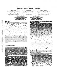
Because of the complexity of the EV7 hardware and the cache coherence protocol, simulation is the only viable validation tool for multi-processor configurations. Using our approach (Fig. 1) we make improved use of simulation resources by (i) making the correctness checking during simulation runs formal and rigorous, and (ii) identifying unexplored or possibly erroneous states of the specification state space and directing simulation runs to these states. Sections 2.1-2.3 present the preliminaries: the TLA+ specification language, the TLC model checker, the EV7 multiprocessing hardware and the cache coherence protocol. Sections 2.4-2.6 describe the innovative aspects of our approach. Section 2.4 describes how the simulator and model checker are linked using a refinement mapping in order to achieve (i). Sections 2.5 and 2.6 explain how a model checker is used to monitor correctness and coverage, and to generate inputs to address coverage gaps. The successful application of these techniques to detect a late-stage design error is also presented in Section 2.6.
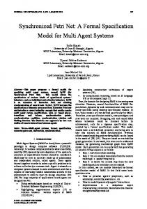
Figure 2: EV7 chip block diagram
2.2 The EV7 Multiprocessing Hardware The EV7 microprocessor provides support for glueless multiprocessing. It contains hardware that enables EV7 processors connected in a two-dimensional torus to act as a cache-coherent shared-memory multiprocessor (Fig. 3). The hardware is composed of tens of sub-blocks with clean, welldefined interfaces. A directory-based cache coherence protocol is implemented by means of two on-chip protocol engines which collaborate with the level 2 cache controller (Fig. 2). The protocol engines are part of the memory controllers and can handle a total of 64 outstanding protocol transactions simultaneously. Both the cache and the memory controllers are deeply pipelined (some 20 stages each), highly optimized, complex circuits. Queues, address and data arrays often have more than one read and write port. There are large (16 or more entries) victim buffers between level 1 and level 2 caches, the level 2 cache and the rest of the system. The network protocol between processors can reorder messages. All of these amount to a hardware implementation that is complex to debug and is far beyond the reach of formal verification tools. Moreover, it has been found that, to exercise certain aspects of the hardware for an EV7 multi-processor system, configurations with more than six processors may need to be simulated. In fact, even simulating such configurations is computationally demanding and often necessitates a distributed simulator running on several CPUs.
Formal specification
Spec violated?
TLC Model checker
Refinement map
Traces to coverage gaps and error states Translation to implementation level
Simulator
Test suites, random tests HDL Model
Figure 1: Simulation directed by a formal specification and a model checker
2.1 The Formal Specification and Protocol Verification Framework TLA+ [4] is a formal language for writing high-level specifications of concurrent and reactive systems. TLA+ is based on the temporal logic of actions (TLA) and incorporates first order logic, set theory, and temporal operators, and is therefore very expressive. TLA+ supports high-level constructs, such as sets, queues, records, and tuples, which arise naturally in high-level specifications but are difficult to express in verification input languages aimed at the register-transfer level. TLA+ has been used successfully for specifying and formally reasoning about complex protocols [1, 7]. In our work, we make use of the explicit-state TLA+ model checker TLC [7]. TLC has two key features that are helpful for dealing with large state spaces. Support for views and symmetry reductions. A view v is a function from a large state space to a smaller one, expressed in terms of the state variables in a TLA+ specification. When a state
Figure 3: An EV7 Multi-processor configuration
357
One disjunct in the TLA+ action ZboxRecvLPResp describing the protocol phase in Fig. 4 is shown in Fig. 5. In this protocol phase, the requestor node (R) sends a request for exclusive ownership of an address (ReadMod) to the home node (H). The states of the cache and the victim buffer (encapsulated in the variable “probe” in line 15) the directory (line 16) and the memory controller (line 14 and a few omitted lines state that the next ZBox entry to be processed for this address contains the ReadMod command) are looked up. Then, the protocol engine sends invalidate messages (SharedInv, line 20) to the nodes that hold copies of that cache line (the “Sharers”, S). The home node also sends a BlkExclusiveCnt, line 18 message to the requestor containing the data at that address and telling the requestor how many invalidate acknowledgements to wait for before modifying the cache line (line 19).
2.3 The EV7 Cache Coherence Protocol The specification for the EV7 cache coherence protocol was written in TLA+ by architects who consulted formal verification researchers. The protocol description, excluding comments, consists of around 2000 lines of TLA+ code. At the time we started applying our approach to verifying the protocol implementation, both the implementation and the specification were mature. The intent was to perform a feasibility study, so that the method described in this method could be used as a mainstream validation tool in a future generation processor design. The original specification for the protocol was in the form of several high-level textual descriptions. Writing the formal specification required translating these into one formal description in TLA+ at roughly the same level of abstraction. This process required rigorous thought about the protocol and the implementation, and was found by the architects to be very beneficial. In fact, the architects chose to start designs for several future processors by describing the protocol design using TLA+ and debugging it using TLC. The EV7 cache coherence protocol is directory-based and implements distributed shared memory. Each processor owns the portion of the address space that resides in the memory chips controlled by its memory controllers. This processor is called the home node for these addresses. The memory controller at the home node is responsible for keeping track of outstanding protocol transactions for the addresses it owns. Requests for a particular address are serialized at the home memory controller. Allowing up to 64 outstanding requests per home node provides high throughput for the multiprocessor system. The protocol specification is parametrized in the number of processors and memory addresses in the system. The specification state variables can be grouped into three, following the structure of the design: variables that represent the cache controller state (the Cbox), memory controller state (the Zbox or DIFT) and variables that represent messages in flight between processors (the Net).
1 2 3 4 5 6 7 8 9 10 11 12 13 14 15 16 17 18 19 20 21 22
module EV 7ProtocolSnippet ∆ ZboxRecvLPResp(addr ) = ∆ let ReleaseDIFTEntry(addr ) = � DIFT = [DIFT except ![addr ] = [reqQ �→ Tail (@.reqQ), state �→ “None”, vicseen �→ “None”]] ∆ SetDir (addr , state, sharers) = � Dir = [Dir except ![addr ] = [owners �→ sharers, state �→ state]] ∆ SetDirExclusiveIfRemote(pid ) = if pid = HomeNode(addr ) then SetDir (addr , “Stale”, StaleOwners) else SetDir (addr , “Exclusive”, {pid }) in ∧ dentry.cmd = “ReadMod” ∧ probe = “Mem” ∧ Dir [addr ].state = “Shared” ∆ ∧ let invaldests = Dir [addr ].owners \ {dentry.reqPID} in Send (BlkExclusiveCnt(dentry.reqPID, CohCnt(invaldests)) ∪ SharedInvalSingles(invaldests)) ∧ SetDirExclusiveIfRemote(dentry.reqPID) ∧ ReleaseDIFTEntry(addr )
24
Figure 5: Part of the TLA+ specification for the home Zbox phase of the protocol scenario in Fig. 4 Since the focus of this paper is verifying implementations against formal specifications, we discuss the issue of verifying properties of the protocol itself only briefly and refer the interested reader to previous papers dedicated to this issue. As described in [1, 7], prior to our work, TLC was used to check the specification for consistency and to prove properties on small configurations for the protocol, i.e. for few processors and addresses. For larger configurations, certain safety properties were proven by hand on the specification since a theorem prover was not available for TLA+ . For these larger configurations, algorithmic verification was limited to checking the consistency of the protocol. While this may at first seem to be a limitation of our method, it is important to note that, because of the complexity of the implementation, even the simplest formal checks, let alone model checking, are prohibitively costly to apply at the implementation level.
Figure 4: An EV7 protocol scenario TLA+ specifications consist of actions, which are essentially disjunctions of guarded commands: if a certain condition holds at the current state, the TLA+ action specifies how the state variables are to be updated and which messages are to be sent. Each action in the EV7 protocol specification pertains to a transaction representing one phase of a protocol scenario, an example of which is shown in Fig. 4. One such phase describes the processing done for a protocol request, forward, or response message at the requesting, home, or sharer processor’s Zbox or Cbox. This description style and structure mimics the original high-level textual description of the EV7 protocol, which itself reflects the multiprocessing architecture. TLA+ became intuitive for the architects after a few days and further discussions were not hindered by language issues.
358
Dir [addr ].state, whereas the specification updates a group of such variables at once (lines 17-22 in Fig. 5. fimpl→int keeps track of the low-level transactions and distributed updates in the hardware for variables representing each intermediate state variable. It aggregates these updates into one atomic update of an intermediate state variable. In a similar fashion, fint →spec aggregates updates to collections of intermediate state variables into one atomic update corresponding to one TLA+ protocol action. Each phase of the mapping establishes a correspondence between variable updates that are distributed in time and space in the lower level of abstraction to an atomic transaction in the upper level. Our approach to constructing these maps is similar to the method of “aggregation of distributed transactions” [5]. The aggregation method associates with each high level, atomic transaction a commit point in the implementation. Transactions in progress in the implementation do not cause a change in the abstract state until they reach the commit point. When they do, the abstraction map computes the implementation state that would be reached if the lower level representation was run to quiescence with no additional transactions (the completion point). Then it computes the projection of the implementation state onto the specification variables. In our maps, we wait until transactions reach the completion point before reflecting their effects on the abstract state. The transactions modify the abstract state in the same order as their commit points, only with an additional delay. We perform the abstract state update specified by an action only if (i) it is completed, and (ii) comes first in the order that the hardware serializes transactions. This serialization order is critical and is explicitly represented in the hardware. Our way of computing the maps can be viewed as a delayed version of the aggregation method. This delayed version has the advantage of avoiding making the completion of a transaction (which is, in effect, simulating the hardware to quiescence) part of the abstraction map. Running the simulator to quiescence at each implementation step is infeasible, both because of the computational cost and the extra requirement from simulators that simulation steps be reversible. Our mapping approach is especially well suited to complex designs where a large team of designers implement hardware sub-blocks. Each hardware designer can construct the portion of fimpl→int relating to his sub-block. Then architects responsible for the overall design can construct fint →spec . This decoupling allows conceptual errors in the protocol to be distinguished from implementation errors, and makes detection and correction of such errors easier. It also makes maintaining the map through the design cycle easier, since modifications to the protocol design or to hardware sub-blocks only modify one component of the map. The abstraction map was implemented as a C++ module that was linked with the simulator (Fig. 1). The mapping module computes fabs incrementally in order to avoid examining all of the implementation state. At each clock phase, after the simulator computes the state transition si−1 → si , the mapping module is invoked and checks if any implementation variable of interest has changed. It then determines if ci = fabs (si ) is different from ci−1 = fabs (si−1 ). If this is the case, it notifies TLC, which checks if the transition ci−1 → ci was legal. Note that TLC is used only to check
Figure 6: The map from the state space of a multiprocessor system to that of the corresponding TLA+ specification. TLC checks whether the transitions c0 → c1 and c1 → c2 are legal.
2.4 The Abstraction Map An execution at the specification level consists of a sequence of atomic protocol transactions, each of which is described by a single TLA+ action. At this level, values of protocol state variables appear instantly available. Each action updates a group of specification variables simultaneously, atomically. This is a much higher level of abstraction than the implementation. One specification state variable, such as the cache state, typically corresponds to a group of implementation variables which may be distributed across the hardware. These implementation variables are not necessarily updated simultaneously or atomically. Accessing and updating these variables require sequences of requests and responses, each of which may take several clock cycles to transmit and receive. This abstraction gap needs to be bridged using a map. In this section, we present our method for constructing such a map. Our approach is distinct in two regards: (i) The effort put into constructing the map enables the formal specification to be used as a monitor during all simulations and (ii) The twophase recipe for constructing abstraction maps presented in this section makes it feasible to apply for verification nonexperts even on a large design. Further, since the abstract model is the protocol specification itself, the construction, analysis, and maintenance of this model is a natural part of the design process. We define the abstraction map as a function fabs (Fig. 6) which maps each implementation state s to a state of the specification c = fabs (s). For each transition in the implementation si−1 → si in a simulation run, we compute ci−1 = fabs (si−1 ) and ci = fabs (si ), and use TLC to check whether the transition ci−1 → ci is allowed by the TLA+ specification. Through the use of an intermediate level of abstraction, we express the map as the composition of two maps. The first map, fimpl→int is from the implementation to the intermediate level, the second, fint →spec from the intermediate level to the specification. The intermediate representation is for better exposition of the mapping process. A state transition model for it is never constructed. The state variables of the intermediate model and the specification are the same but the level of atomicity is different. The atomic transactions at the intermediate level are updates to a single intermediate state variable, such as
359
While it is possible to collect coverage information by writing coverage measurement code observing the implementation state only, inferring the coverage information also requires translation from the time granularity and signal representation of the implementation to the protocol level. Using the formal specification and the mapping for this purpose as well avoids duplicated work and makes coverage data collection more rigorous.
a single specification-level state transition. The time spent by TLC, which is run as a parallel process, to check and record one such transition is negligible compared with the cost of simulating. Our rudimentary implementation results in about 100% simulation overhead. The portion of hardware involved in the map was described using approximately 20 thousand lines of HDL code. The map itself took eight thousand lines of C++ code, excluding comments, which is roughly the same size as implementation level checkers that had been previously written. The map was constructed by a formal verification researcher after the design was complete, which made the process time consuming. The cache coherence hardware of a future generation microprocessor design was first specified using TLA+ and it was expected that the task of extracting the information from the design required for such a map would be passed down to the implementors of hardware components as described above. Our method provides an iterative process for debugging the specification, implementation, and the abstraction map together. Whenever an inconsistency between the implementation and the abstraction is detected, either the abstraction map is modified or the implementation and/or protocol specification are corrected. In each case, the quality of verification is improved.
2.6 Addressing Coverage Gaps Possibly the most important benefit offered by our approach is the facilitation of coverage-guided validation. In the later stages of the functional validation process, assignments to coverage variables that have not been exercised during simulation are identified as coverage gaps. These then serve as targets for TLC, which is used to explore the protocol state space, and to generate a trace to the target if one exists. A path to a target state generated by TLC is intuitive to understand, and is a very valuable aid for simulation input generation. Since the abstract specification closely reflects the structure of the EV7 design, translating this path into a simulation run of the EV7 is a manageable task. Typically, translating a specification-level run into an implementation run involves writing a script to convert high level protocol messages to clock accurate representations at the input pins of a processor, and experimenting with the timing of consecutive messages. Due to the complexity of the implementation, it is a much more formidable task to generate the same simulation run without being provided a protocol-level path. A major difficulty in making use of coverage information is identifying which coverage gaps are due to insufficient simulation and which ones are scenarios that cannot happen. The use of formal specifications for coverage measurement alleviates this difficulty. Formal verification tools such as TLC can determine or conservatively estimate whether a coverage target is reachable or not. Coverage gaps that appear due to insufficient simulation can then be given priority in test generation.
2.5 The TLC Model Checker as a Monitor Once the abstraction map is constructed and linked with the simulator, during all subsequent simulations, TLC can be used as a monitor that checks consistency with the protocol specification. Since at each step of the simulation the abstraction map produces a protocol-level state, when an error is signaled by TLC, the sequence of states produced by the map up to that point provide a high-level trace, which is a useful aid for debugging. If TLC signals an error, the spec-level trace up to that point can be used to determine whether there was an error in the construction of the map, or whether the hardware in fact performed an illegal operation. This is an improvement over checkers that implicitly perform both the abstraction and the consistency checking, since these two aspects of the protocol consistency verification process are decoupled and therefore verified and debugged separately. A significant feature of our approach is the fact that an error is signaled the first time the hardware performs an operation inconsistent with the specification. This provides strong justification for high-level, executable specifications, and model checkers that can handle them. We use TLC to store the specification states covered during simulation. In this way, coverage information is collected at the same time protocol conformance is being tested. To keep coverage data managable, we make use of symmetry reductions and views as described in Section 2.1. A view in effect designates a subset of specification variables as coverage variables. One natural choice for a view is the tuple of variables that the case splits in protocol phases are based on. These were the same variables used in the text description for the protocol for coverage measurement during prior simulations: the memory controller state, the result of the cache, victim buffer and directory look-ups, and the type of the message the memory controller is processing. All of these are specification state variables. The late-stage design bug described in the next section was directly related to a gap according to this notion of coverage.
Figure 7: The late-stage design bug To demonstrate the viability of our approach, we selected a bug (Fig.7) from the EV7 bug database that was discovered only after the first hardware prototype was built and tested in an eight processor configuration. We deliberately chose such a bug to make sure that it was unlikely to exercise it during random simulation or pre-silicon directed tests. A description of the bug follows.
360
3 proc.s 4 proc.s
1 44s, 3K, 15 21m, 53K, 21
Requests per proc. 2 3 33 m, 79K, 25 5h, .7M, 38 >8h, >1.2M, ? >8 h, >2.8M, ?
Table 1: TLC run-time, size (number of states) and diameter of the state space Initially, a memory address (addr0), whose home node is processor 0, is in shared state in processors 0, 1, and 2. The home node asks for exclusive access to the address (SharedtoDirty[1] in Fig. 7 and gets it. Later, it evicts this line from its cache (the Victim message in Fig. 7). In the meantime, processors 1 and 2 ask for exclusive access to the same line (SharedtoDirty[3] and [4], respectively). The victim message remains pending in the victim buffer because of too many other memory requests keeping the memory controller busy. SharedtoDirty[3] is refused due to the eviction in progress. The protocol design implicitly assumes that after this refusal, the victim will make its way to the memory controller and resets the associated “inflight” bit. SharedtoDirty[4] is processed by Zbox0 as if there is no victim message in flight. But then Zbox0 receives the Victim message while processing SharedtoDirty[4]. Since this scenario was not anticipated, no next state had been specified in the protocol engine specification or implementation. This unexpected victim message causes an assertion violation during a model checking run using TLC on a single-address, three-processor configuration. This particular model checking run took less than five minutes and about 30 MB of memory on a 625 MHz Alpha server. It was confirmed with the architects that if they were given the protocol-level trace produced by TLC before the bug was discovered, they could easily have produced a corresponding run in the implementation. We then repeated the simulation run that exercised this bug, this time using TLC as a correctness monitor. The simulation was consistent with the (buggy version of the) specification throughout the run. This proved that the protocollevel error trace was an actual bug in the implementation and was not due to the protocol specification containing too much non-determinism. The fact that our methodology could be used to identify a protocol-level trace and to verify that it is indeed a trace in the implementation and leads to a real error demonstrates the power of our approach. The work described in this paper was a demonstration of concept, rather than the primary means of verification for the EV7. Therefore, the experimental results presented are limited. As a measure of the complexity of the protocol and TLC’s performance, Table 2.6 lists some performance data.
3.
transactions. Perhaps more importantly, the EV7 specification reflects the internal architecture of the multiprocessing engine, and is thus better suited for measuring coverage and directing simulation to exercise all aspects of the hardware. The EV7 protocol specification can also be viewed as a detailed functional coverage model similar to those in [3]. The fact that our specification is executable and that there are verification tools that can be run on it addresses a key issue pointed out in [3]: determining whether coverage gaps are true deficiencies in validation or are due to the coverage model being too general. The techniques described in [3] can be used to limit the number of coverage targets for TLC. Our work is similar to [2] in making formal verification tools and simulation collaborate. However, the existence of a highlevel, executable formal specification and tools for reasoning on it distinguishes our approach.
4. CONCLUSIONS We presented a technique for using formal specifications of hardware as simulation monitors, coverage analysis, and coverage-guided generation of simulation input vectors. Our approach makes the process of checking functional correctness during simulation formal and rigorous, and enables formal coverage analysis, and automation for directing simulation runs towards coverage gaps. We demonstrate the efficacy of our approach on verifying the cache coherence engine of the Alpha 21364 microprocessor.
Acknowledgements We would like to thank Maurice Steinman, Brian Lilly, Luka Bodrozic, Kathy Menzel, Jonathan Nall, Rajeev Joshi, Scott Kreider and Scott Taylor for their contributions to this work.
5. REFERENCES [1] H. Akhiani, D. Doligez, P. Harter, L. Lamport, M. Tuttle, and Y. Yu. TLA+ Verification of Cache-Coherence Protocols http://research.microsoft.com/users/lamport/tla/fm99.pz.Z. [2] P.-H. Ho, T. R. Shiple, K. Harer, J. H. Kukula, R. Damiano, V. Bertacco, J. Taylor, and J. Long. Smart simulation using collaborative formal and simulation engines. In Proc. Intl. Conf. on Computer-Aided Design, pages 120–126, Nov. 2000. [3] O. Lachish, E. Marcus, S. Ur, and A. Ziv. Hole analysis for functional coverage data. In Proc. 2002 Design Automation Conference, 39th DAC, pp. 807–812, 2002. [4] L. Lamport. Specifying Systems: The TLA+ Language and Tools for Hardware and Software Engineers. Addison/Wesley, 2002. [5] S. Park and D. L. Dill. Verification of Cache Coherence Protocols by Aggregation of Distributed Transactions. In Theory Comput. Systems, Vol. 31, pp. 355–376, 1998 [6] K. Shimizu and D. L. Dill. Deriving a Simulation Input Generator and a Coverage Metric from a Formal Specification In Proc. 2002. Design Automation Conference, 39th DAC, pp. 801–806, 2002. [7] Y. Yu, P. Manolios, and L. Lamport. Model checking TLA+ specifications. In Proc. IFIP Working Conference on Correct Hardware Design and Verification Methods, CHARME, Lecture Notes in Computer Science 1703, pp. 54–66, 1999.
RELATED WORK
In [6], similar to our work, the same formal description is used for collecting coverage information and deriving simulation inputs. The formal description in that case is a list of interface properties describing a bus protocol. Our work is different in several regards. First, the specification for the EV7 cache-coherence protocol is at a more abstract level than the more cycle-accurate, RTL-level interface specifications in [6]. This necessitates an abstraction map, but in return provides tools for reasoning at a higher level. Second, the properties in [6] are very localized in time, for instance, they can not express constraints on bus protocol
361