Mar 11, 2012 - Implementation of a TUI Application on an Apple iPad 2 .... more focused on interaction and interface designs that free the user .... for this paper, no application could been found that uses a mobile device to realize a ..... For further development, a git source code management repository has been created at.
HTW Berlin (University of Applied Sciences)
WS 2011/2012
Media and Computing (Master) Faculty of Business Sciences II
Paper
Building a Portable Low Cost Tangible User Interface Based on a Tablet Computer Markus Konrad March 11, 2012 Supervising tutor: Prof. Dr. Klaus Jung
Contents 1. Introduction 1.1. Initial ideas . . . . . . . . . . . . . . . . . . . . . . . . . . . . . . . . . . 1.2. Fundamentals . . . . . . . . . . . . . . . . . . . . . . . . . . . . . . . . . 2. reacTIVision framework and tablet computers
2 2 4 10
3. Implementation of a TUI Application on an Apple iPad 2 11 3.1. Backend: Modification of the reacTIVision framework . . . . . . . . . . . 12 3.2. Frontend: An example application . . . . . . . . . . . . . . . . . . . . . . 13 3.3. Performance and validation of the prototype . . . . . . . . . . . . . . . . 17 4. Conclusion
18
5. Appendix
19
A. References
19
B. Provided source code and software
22
1
1. Introduction This paper covers the topic of how to use a modern tablet computer with its integrated camera to implement a tangible user interface (TUI) , which can become very handy in cases where battery-driven power supply, low weight and portability are crucial. It is important to mention, that the tablet is used both as application backend to process camera input, identify and track tangible objects like markers, touches and so on, and as application frontend that receives the processed information about these objects (like position and rotation of markers) and provides feedback for the user. For this work, the Apple iPad 2 has been used to implement and test this approach, while other tablet devices running for example with the Android operating system, might also be adopted to this field of application. This work is separated into three parts: The first gives an overview about the basic idea as the fundament of this work as well as a short introduction to the fundamentals of tangible user interfaces. It covers basic image processing for fiducial recognition and also the protocols used in such applications to provide the thereby extracted information to the application frontend. The second part shortly describes the possible usage of the reacTIVision framework on a tablet computer and the third part describes the implementation of a prototype for the initially proposed idea. In the last section a conclusion is made and further development is discussed.
1.1. Initial ideas The basic idea for this work came with the introduction of tablet computers equipped with integrated cameras (most of them in the front and back side of the device), that are both powerful enough to perform complex image processing tasks while being small in size, low at weight and cost and having a battery-driven power supply. In cases where TUI devices needs to be moved around and have no constant power supply, like for example in a mobile museum or a mobile art installation, most “classical” TUIs like the Reactable Experience 1 , Reactable Live! 2 or Microsoft Surface 1.0 3 cannot be adopted, because they are either not portable enough, do not have an (inbuilt) battery power supply or are simply much to expensive. As stated later in section 1.2.1, many table-top tangible user interfaces consist of a (semitransparent) surface that can be touched and/or on which objects with markers can be placed, a (infrared) light and a (infrared) camera that captures the backside of the 1
Reactable Experience technical specifications: http://www.reactable.com/products/reactable_ experience/ 2 Reactable Live! technical specifications: http://www.reactable.com/products/live/ tech-specs/ 3 Microsoft Surface 1.0 technical specifications: http://technet.microsoft.com/en-us/library/ ee692114(v=surface.10).aspx
2
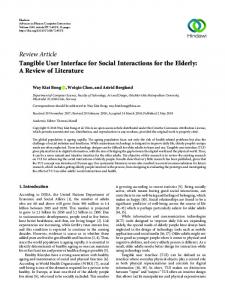
surface so that the markers and/or touches can be seen and a computational device that processes the camera images to find out and track the markers and/or touches. After processing the camera input, that tracking information is sent to a frontend application that provides feedback to the user. The basic approach is now to let the tablet device take over the parts of the backend and the frontend application to have a very compact layout with only a portable single device and a light source for implementing a TUI application. The initial idea was that the tablet device can be placed right next to a semitransparent surface and the tablets camera on the backside can capture the backside of the surface via two mirrors as shown in figure 1. The captured image on the second mirror can then be processed by the tablet and possible feedback can be given in an acoustic and visible way on the tablet device itself. With this simple approach it is not possible to display an image for feedback on the surface again, as most TUIs do, but it allows to use the tablet device for feedback and as second interaction surface. The tablet would therefore be extended by a bigger surface with tangible objects.
tablet computer w/ camera
objects with markers semitransparent surface
light source mirror
mirror
Figure 1: Initial layout of a TUI interface with a tablet computer This layout could be extended as shown in figure 2 by adding a small projector to the tablet (for example a USB-connected mini-projector) that might display an image on the surface as feedback for the user, while the tablet device is completely hidden in the module. This way, the whole device would act like a “classical” TUI. Of course this would also induce problems with distortion of the captured camera image, because the projected light would overlay it. Therefore an infrared light and a filter in front of the camera needed to be used, so that only infrared light reflected from the markers is visible to the tablet’s camera. Based on this approach, the most simple way to implement a TUI on a tablet device, would be to abandon visible feedback completely and only provide acoustic feedback. This way the user can only hear information from speakers or headphones, which is sufficient in many contexts, for example for installations in a museum or in schools. The layout for this approach is shown in figure 3. It has been implemented as part of this work and is documented in section 3.
3
objects with markers semitransparent surface
infrared light source projector tablet computer w/ camera Figure 2: Extended layout with additional projector
objects with markers semitransparent surface
tablet computer w/ camera
light source
Figure 3: Simplified layout that only provides audio feedback This simple and compact layout is both powerful and flexible, while further extension is easily possible: For example one can imagine to add another tablet computer or a display, which is visible to the user and acts as the frontend with visible feedback and further interaction possibilities.
1.2. Fundamentals This section shortly covers a few fundamentals regarding tangible user interfaces. For more extensive research please refer to works like Tangible User Interfaces: Past, Present, and Future Directions [SH10] by O. Shaer and E. Hornecker or the proceedings of EuroHaptics 2010, Amsterdam [KvETvdH10].
4
1.2.1. Tangible User Interfaces Since the late 90’s, the research field of human computer interaction (HCI) has more and more focused on interaction and interface designs that free the user from being “chained” to a mouse, a keyboard and a desktop computer. One of these new interaction approaches is called Tangible Interaction, proposed by Hiroshi Ishii and his fellow researchers at the MIT Media Lab in 1997 [IU97]. As stated by Eva Hornecker, this approach focuses on user interfaces, that emphasize features like tangibility and materiality of the interface, physical embodiment of data and whole-body interaction [Hor09]. So the general idea is that not monitor screens with abstract windows, icons, menus and pointers (so called WIMP interfaces) represent information but real physical objects, that in this way are augmented with digital data. One of the first implemented application of this type was the Marble Answering Machine by Durell Bishop4 . In contrast to classic WIMP interfaces, TUIs generally provide feedback for different senses: Interaction with objects and touches on surfaces provide haptic feedback, (two or three dimensional) visual and/or auditory feedback informs the user about the reactions of the system. Because of this, there is a huge variety of interaction styles and concepts that can be called tangible and they imply usage of very diverse technologies from Computer Science and Electrical Engineering. Many of them for example make use of algorithms from the field of Computer Vision, while others use radio-frequency based technologies (e.g. RFID or NFC) or sensors and actuators. A comprehensive comparison of these technologies is done in [SH10]. Not only the implemented technologies, also possible application domains differ very much. B. Ullmer and H. Ishii specified twelve different application domains for TUIs, including Information storage, retrieval, manipulation and visualization, Simulation, Modelling, Education, Programming systems and Collocated collaborative work [UI00]. Shaer and Hornecker also added Music and Performance as popular area of TUIs, especially referring to the later described reacTable [SH10]. As seen, the mentioned application areas and implemented technologies are quite comprehensive. As the initial idea for this work is based on optical marker recognition, this work concentrates on Computer Vision technologies for TUIs. The possible application areas for the proposed idea seem to be ideal for educational purposes (e.g. usage in (mobile) museums and workshops) and collaborative work (also including music and performance), but have to be validated later. 1.2.2. Related TUI concepts and applications The proposed idea is an adoption of an already successfully implemented TUI concept, that uses optical markers (fiduciary markers or fiducials) attached to physical objects 4
A video of how this machine works is available at http://www.formfollowsfuckingfunction.net/ 2011/11/01/marble-answering-machine/
5
to recognize them individually and calculate their position, orientation and size. This approach is called tag-based computer vision. Some other research projects have already explored the possibilities of such a system, many of them connected to interactive music and composition. An example is the Music Table from the ATR Media Information Science Laboratories that uses ARToolKit for tag recognition and allows one or more users to create simple melodies and rhythms by arranging fiduciary markercards [BMHS03].An earlier system, that has also partly been developed at ATR Labs and implements a comparable interaction and tag recognition system, is the Augmented Groove [PBK+ 00]. One of the most popular TUIs that implement tag-based computer vision is the reacTable, which is described by its creators as a novel multi-user electro-acoustic music instrument with a tabletop tangible user interface [...] [JKGB05]. The image processing backend of this system is the open-source computer vision framework reacTIVision, which will be described later in greater detail. The fundament of reacTIVision’s fiducial recognition system is the topological recognition approach which has initially been invented and implemented in three tangible music toys called audio d-touch by E. Costanza et al [CR03]. This approach will also be introduced shortly in the next section. As stated in [BKJ05], this system could be strongly improved in terms of performance and reliability and let to the development of the open-source computer vision software library libfidtrack, that is now the default fiducial recognition system used in reacTIVision. Another well-known advanced TUI is Microsoft Surface. Version 1.0 has been released in 2008 and features a multi-touch and object tracking system based on five near-infrared cameras [And11]. In 2012 the successor product Surface 2.0 had been introduced. Instead of a camera tracking system, it uses a technology called PixelSense. In Surface 2.0 each pixel has a sensor for infrared light that is reflected back from objects or fingers on the table. With this system, it was possible for Microsoft to reduce the thickness from 56cm to 10cm [Mic11]. Unfortunately the details of the technology are not available to the public and the hardware is of course much more expensive in production than the individual parts one needed for a classical camera based TUI. There are lots of Augmented Reality (AR) applications available for mobile devices such as the iPhone, iPad or Android tablets/phones, but they usually only provide additional information in the users surroundings in a “video see-through” manner. In research for this paper, no application could been found that uses a mobile device to realize a table-top TUI. 1.2.3. Real-time fiducial recognition The goal of real-time fiducial recognition is to find out the position, orientation and scale of an optical marker as well as its unique identification features while providing a decent update rate. Most of them also calculate the position and orientation of the
6
camera relative to the marker. Fiducial recognition algorithms can be divided into three fundamental approaches: Color-based recognition, detecting geometrical features and the topological approach. A color-based approach using colored rings as fiducials has been proposed by Y. Cho and U. Neumann in 1998 [CN98]. H. Kato and M. Billinghurst used square markers with a specific size, calculating the transformation and orientation matrix for the camera (extrinsic parameters) from information about parallel sides of the markers and the perspective projection matrix P (intrinsic parameters) [KB99]. The later can be described as the camera coordinates in 3D space in relationship to the camera screen coordinates in 2D (the captured image). P is initially calculated using a cardboard frame with a grid and calculating the relationship between the found cross points of the grid and the camera coordinates (calibration). The whole process is called homography and is also used in ARToolKit. To identify individual markers, ARToolKit also does simple template matching after perspective correction of the found markers.5 Topological approaches have mostly been used in non real-time, but Costanza et al. [CR03] simplified the complexity of existing methods to enable topological fiducial recognition to be done in real-time applications by using a binary threshold and introducing constraints to the adjacency information of the fiducials. The algorithm can be summarized in the following way: 1. Adaptive binary thresholding. Costanza et al. introduced an algorithm that utilizes a laplacian filter for thresholding, so that changes from black to white or vice versa tend to happen only on the image edges. The resulting binary image is less prone to lighting changes than those calculated from “classic” adaptive thresholding images and homogeneous areas are better segmented. 2. Building the Region Adjacency Tree or Scene Graph G. For a binary image an adjacency graph can be constructed in a recursive procedure, that results in an undirected graph with information about which image areas contain which subareas, which again contain which sub-subareas and so on. Figure 4 shows an example of such a graph. 3. Searching the Region Adjacency Tree for fiducials. The task is now to find out, whether for each fiducial graph H, we can find an isomorphic subgraph in G. This is a classical NP-complete problem in Computer Science [Epp99]. Costanza et al. limited the graph-depth of the fiducial tree to 3 levels (root, branches and leaves), which means that for each fiducial tree H, G must be traversed only once for fiducial recognition. Because the fiducial is limited to only 3 levels of depth, it can be easily and uniquely identified by creating an integer sequence that describes the number of leaves in each branch.6 5
Refer to http://www.hitl.washington.edu/artoolkit/documentation/vision.htm for further information about ARToolKit’s Computer Vision Algorithm. 6 For example the integer sequence (0, 0, 1, 2) indicates that the fiducial has 4 branches, two of them with no leaves, another with 1 leave and the last one with 2 leaves.
7
R 0
R
0
1
1 a
b
c a
b
c
Figure 4: Example of an adjacency tree As Costanza et al. point out, a big advantage to geometrical fiducial recognition is that the topological approach is very tolerant to deformations as long as their topology is preserved, which allows them to be used on soft materials (e.g. clothes). Furthermore, extra information can be encoded into the tags, because the recognition algorithm decodes the information structure of a tag and not just applies simple template matching as for example in [KB99]. The overall recognition and performance results were very satisfying and led to the development of the already mentioned d-touch tangible music toys and the open-source software library libdtouch. The proposed approach of Costanza et al. also has some shortcomings, that were pointed out in [BKJ05] by Bencina et al. The main problem in d-touch is, that location and orientation cannot to be calculated from the adjacency tree structure of the fiducials and must be determined using traditional Computer Vision algorithms. Another problem is, that the d-touch fiducial design makes it hard to minimize the fiducial size. Bencina et al. solved these problems by making maximum use of the region adjacency graph and the data encoded in the fiducials. The main differences to the work from Costanza et al. are: 1. Calculating the fiducial location and orientation by using information encoded in the fiducial. The center point of the fiducial is defined as the weighted average of all leaf centers. The orientation vector is calculated from this point to the weighted average of all back (or white) leaf centers. 2. Random fiducial tree generation. All generated fiducials that meet certain criteria (number of nodes, maximum node depth, number of black and white leafs) form a set. 3. Generated fiducial tree geometry. A genetic algorithm ensures that programmatically generated fiducials have an optimized design according to centroid locations, area, aspect ratio and symmetry.
8
4. Forming a canonical name for fiducials from Left Heavy Depth Sequences for recognition in the scene graph. Depth sequences can be formed by traversing through a graph and noting down the depth (amount of edges between this node and the root) of each node. To prevent ambiguities, the traversing order always prefers heavier nodes at first, meaning nodes with the strongest depth. This approach has proven to be reliable and fast (over 4 times faster than d-touch [BKJ05]) and at the same time it allows smaller fiducial sizes. It has been implemented in libfidtrack which is part of the reacTIVision framework and will later be described in more detail. 1.2.4. Protocols for TUI Applications In many cases, it is reasonable to detach the TUI application backend (performing the mentioned computer vision tasks) from the frontend (giving audio and/or visual feedback to the user). This enables to run both interconnected application tasks on different machines, even allowing to have multiple backend or frontend applications at once. The TUIO protocol [KBBC05] has been designed to meet these requirements in the context of table-top TUIs. It is based on the Open Sound Control (OSC) protocol [WFM03] and therefore available on any platform that supports this protocol. Like OSC, TUIO usually uses UDP port 3333 for communication. The TUIO protocol has been designed to be flexible, fast and insusceptible regarding possible packet loss. Therefore two main message types have been defined: Alive and Set messages. The first type only includes a list of objects that are currently placed on the surface. The second type contains information about an object’s current state, such as its position, orientation and so on. By frequently analyzing the object ids sent with the alive messages, the application frontend can easily determine, which objects are currently present and keep a list of these objects. Their properties can be updated by analyzing the set message of each object. Each update state can be tagged with a unique frame sequence id, that can be submitted using the third message type, fseq message. The updated TUIO 1.1 specification also includes a fourth message type, source message, that allows “[...] the possibility of multiplexing multiple tracker sources” [Kal09]. Besides transporting information about fiducials (tagged objects in TUIO specification) and finger touches (cursors), the updated specification introduces a third profile to communicate information about untagged objects (blobs). Using this profile, a TUI backend can for example inform the frontend about basic geometrical features of a (non-fiducial) object that the user has laid on a TUI surface, such as a mobile phone or a glass. To make use of the TUI protocol, one can rely on working OSC implementations such as oscpack 7 or liblo 8 . There are also specific TUIO protocol implementations, many of 7 8
oscpack Open Source software library by R. Bencina: http://www.rossbencina.com/code/oscpack liblo Open Source software library by S. Harris and S. Sinclair: http://liblo.sourceforge.net/
9
them based on the mentioned OSC libraries9 . The TUIO protocol is also implemented in the already mentioned reacTIVision framework.
2. reacTIVision framework and tablet computers From all already mentioned Computer Vision or TUI libraries and frameworks, reacTIVision is considered to be the one that fits best for the initially proposed idea in section 1.1. It was shown in [BKJ05] and [Kal09], that the underlying algorithms for this framework allow robust and fast fiducial recognition. As described on the website10 , “reacTIVision is a standalone application, which sends TUIO messages via UDP port 3333 to any TUIO enabled client application”. This means, that reacTIVision is more a full-featured TUI backend application, than a classic framework or software library and takes care of all fiducial recognition tasks and sends the results via OSC to a frontend11 . As shown in figure 5, the framework is built around four main components, which in turn are all separate Open Source projects12 . camera reacTIVision
input image
libfidtrack
portvideo
tracking inform.
SDL
oscpack
output image (preview display w/ recognized fiducials)
display display
TUIO message
network
Figure 5: ReacTIVision software components 9
A list can be found at http://www.tuio.org/?software reacTIVision Open Source framework: http://reactivision.sourceforge.net/ 11 Besides TUIO messages, reacTIVision is optionally capable to send MIDI information using the portmidi library from http://sourceforge.net/apps/trac/portmedia/wiki/portmidi. 12 To this point not mentioned libraries: portvideo camera framework (http://portvideo. sourceforge.net/), SDL Simple DirectMedia Layer (http://www.libsdl.org/) 10
10
The framework’s behavior can be considerably configured using a XML file for basic settings or using keyboard commands for on the fly configuration of computer vision parameters. The reacTIVision stand-alone application is available for Mac OSX, Linux and Windows, but there is no implementation for mobile or tablet devices. Using this framework therefore implies, that it must be at first ported to a mobile device operating system such as Android or iOS, meaning it should compile on the platform (with ARM architecture), process images captured with the in-built camera and send TUIO messages. When trying to port a computer vision framework to tablet computers, mainly two restrictions have to be considered: Limited hardware resources and fewer image quality of the in-built camera. As the proposed idea wants to unite application backend and frontend on one device, limited hardware resources are an important problem, because computational resources on the device must be sufficient for both, the reacTIVision backend and an application frontend with audio and/or visual feedback. Furthermore, low resolution cameras with low frame rates might result in bad fiducial tracking on fast movements. These points must be later examined with test implementations.
3. Implementation of a TUI Application on an Apple iPad 2 The goal for test-implementation of the mentioned idea was to find out, if it is possible to deploy the reacTIVision framework on a tablet computer and if so, the recognition rate of the fiducials as well as the overall performance of the system should be measured and analyzed. For a test-implementation of the mentioned idea, a table-top TUI based on an iPad 2 tablet computer was realized. The hardware specifications of an iPad 2 read as follows [Ngu11]: • 1 GHz dual-core CPU • 1 GB RAM (of which only up to 50% can be used by a single application) • 2 cameras with the capability to capture images at 30 fps (one camera on the backside with 720p and one on the frontside with VGA resolution) As seen in figure 6, a semitransparent surface is mounted in a cube chassis and on the bottom side the iPad sits in a fitting. Furthermore, a simple flashlight for illumination is used. This is only an interim solution for a basic application test and should later be replaced by infrared illumination.
11
illustration w/ fiducial
semitransparent surface
illumination
iPad 2
Figure 6: The TUI table prototype and its components
3.1. Backend: Modification of the reacTIVision framework The reacTIVision framework runs on different platforms: Mac OSX, Linux and Windows. It does not compile for Apple’s mobile operating system iOS though and so some modifications had to be done to the source code. First of all, code for MIDI support in reacTIVision had to be disabled, because iOS is not supported by the portmidi library and resolving this problem is not part of this work. Secondly, a recent beta version of the SDL library had to be integrated and compiled for iOS as described in [Ron11]. Some modifications had to be done to the SDL so that images can be displayed in landscape orientation mode and access to the root view controller is possible13 . A crucial step was to get camera images into the reacTIVision framework. The iPad 2 cameras are not supported by the portvideo camera framework, which is integrated into reacTIVision and provides standard, platform independent access to cameras. Therefore a new camera driver was written for portvideo, to support cameras for all iOS devices: 13
Some missing statements in SDL uikitviewcontroller.m did prevent getting access to the UIApplication root view controller.
12
iThingCamera. The driver mainly makes use of Apple’s AVFoundation-API. With the mentioned modifications, it was possible to successfully compile and run reacTIVision on an iPad 2. Fiducial markers were recognized, identified and tracked. The successful deployment of the application backend now allowed to build a frontend application.
3.2. Frontend: An example application To test and analyze the usability and performance of a TUI application on an iPad 2 with reacTIVision, a small “assignment game” was conceived, that should, as an example, illustrate Jewish dietary laws or Kashrut [Ric11] laws. The main idea of such an assignment game is that certain objects can be placed on labeled areas on a table. Regarding the kashrut laws, these objects would be illustrations of different types of food, such as eggs, fish or a cheeseburger and these illustrations could be assigned to four different areas on the table: dairy, neutral, meat and unkosher food. 3.2.1. Control overlay for the GUI
Control bar
Fiducial placed in neutral area
Areas for each type of food
Figure 7: reacTIVision on iPad GUI
13
Figure 8: reacTIVision on iPad in calibration mode The original reacTIVision application allows to control camera parameters and other settings via keyboard commands. It is also possible to calibrate the camera using the keyboard. Since neither using an external Bluetooth keyboard nor using the on-screen keyboard would be convenient, a small overlay bar for application controls was created, as seen in figure 7. It allows easy camera calibration by modifying the displayed grid in figure 8 until it fits to a calibration sheet that can be downloaded from the reacTIVision website14 . Furthermore, the control bar allows to switch between the two iPad cameras, set the display mode (input image, processed image, no image) and enable/disable an overlay for the implemented frontend application. When the system will later be extended by a projector that is connected to the iPad, only the frontend should be projected on the surface and the controls should be hidden. This can be achieved by compiling the application in release mode, thus disabling the controls GUI with preprocessor switches.
14
TUIO command source alive set
fseq
Parameters Source host that send this message List of session ids for each recognized object Session id for the object, class id (fiducial number), position, angle, size, movement velocity vector, rotation velocity, motion acceleration, rotation acceleration Unique frame index number
Table 1: TUIO commands and parameters 3.2.2. Receiving and processing TUIO messages As described in section 1.2.4, the reacTIVision framework constantly sends TUIO messages in OSC format on each processed frame. The four TUIO commands of protocol version 1.1 are outlined in table 1. To receive and process these messages, the frontend application must listen on port 3333 of localhost for UDP packets, which contain OSC messages that in turn must be parsed. With oscpack, reacTIVision already contains a library that fulfills these requirements, because it is used by the backend to send out these OSC-formatted TUIO messages in the first place. It is possible to utilize this library now for reading them. To do so, a class TUIOMsgListener has been created, that inherits from the abstract oscpack class OscPacketListener. The virtual method ProcessMessage was implemented to analyze the parameters of a received OSC message and transform it into a TUIO message format, which is represented by a struct with a member named data of type union. This structure, as seen in listing 1, can hold all four different types of TUIO messages. TUIFrontendCore handles the main frontend application logic and also takes care about incoming TUIO messages. Upon receiving a message, its method receivedTUIOMsg is called. Depending on which TUIO command was received, it either adds or removes TUI objects with the help of the submitted session ids (alive message) or updates their properties (set message). In each case, a delegate object gets informed about the events. In this case, the only observer of TUI events is the KashrutGame object, whose implementation is described in the next section.
typedef struct _TUIOMsg { TUIOMsgType type ; // tagged obj ., cursor / touch or blob TUIOMsgCmd cmd ; // source , alive , set or fseq union _data { struct { // for cmd = source char * addr ; // string with source host 14
See http://reactivision.sourceforge.net/#usage.
15
} source ; struct { // for cmd = alive int * sessIds ; // array w/ length of numSessIds unsigned int numSessIds ; // number of sess . ids } alive ; struct { // for cmd = set int sessId ; // session id int classId ; // fiducial marker id TUIOMsgVec pos ; float angle ; TUIOMsgVec size ; float area ; TUIOMsgVec vel ; float angleVel ; float motAccel ; float rotAccel ; } set ; struct { // for cmd = fseq int frameId ; // unique frame seq . number } fseq ; } data ; // ... } TUIOMsg ; Listing 1: TUIOMsg structure
3.2.3. Implementation of the “Kashrut” game In the class KashrutGame, the game logic is implemented.Four different fiducial ids that can be used in this game are associated with a food type (diary, neutral, meat or unkosher). An illustration that has the fiducial with such an id applied to its backside, will be recognized as one of the four food types. Furthermore, four “food areas” are defined, one for each food type. These are the areas where the illustrations can be placed and will be identified as either correctly or falsely placed. As mentioned in the previous section, KashrutGame will be informed about TUIO events, therefore the TUIObjectObserver protocol has been implemented with methods that are called upon adding, updating and removing a TUI object. So each time a TUI object was added or updated (i.e. the position changed), its food type is determined by using its fiducial id and the current food area in which it is placed is found out by checking its position. Depending on the result, a sound is played to report either game success or failure.
16
3.3. Performance and validation of the prototype For validating a TUI system in terms of its technical behavior, recognition rate, stability and speed are the most important features to analyze. These features should be as independent as possible from environmental influences. For usage in a mobile (battery powered) environment, CPU usage is also very important, because this affects the energy usage and therefore the overall run-time of the system. At first, the overall performance was measured by analyzing the frame rate of the system. The achieved frame rates are about 4 to 5 frames per second, when the frames are also displayed on the device’s screen, which is normally only enabled for debugging. Without this, the achieved frame rate is doubled. The recognition speed is in both cases very high and the feedback appears instantly to the user. Unfortunately, the recognition stability is greatly affected by the bad image quality and low frame rate, that is delivered from the iPad’s front camera. Once a fiducial is recognized it usually does not get lost by the tracker as long as it is not or only slowly moved. But when the fiducial is moved faster, the image delivered from the camera gets very blurry, which prevents the system to recognize its fiducial structure and therefore gets lost for the tracker. When the movement stops, the fiducial is again detected immediately. Using Apple’s profiling software Instruments, CPU and memory usage was examined. The former was very high, with CPU activity of about 163% on the dual-core processor, resulting in about 82% overall activity. Memory usage was modest with about 20 MB. The high CPU activity might result in slower frontend reactivity, when the frontend GUI becomes more complex in future applications. Furthermore, the high CPU usage results in higher energy consumption, but tests have shown, that the application consumes about 10% battery power per hour when running constantly, which is accaptable. For example, playing a video nonstop on an iPad 2 causes about 11% battery power consumption per hour [Gal11]. As a matter of fact, the system’s recognition rate and stability are for now very dependent on the illumination of the room it is located in. Because camera and backside illumination do not operate in infrared light, each external light source interferes with the captured camera image and impedes proper fiducial recognition. This circumstance can be easily avoided by using infrared illumination and an infrared filter in front of the camera, which will be added later to the system but was not available at the time of development. A further improvement would be to use the camera on the back side of the iPad 2, since it delivers better images (720p compared to VGA resolution on the front side). For the implemented game, the achieved overall performance is completely sufficient as well as the recognition speed and stability. The problem that fast moving fiducials are not properly detected is not important for this type of application, but might have
17
negative influence on applications where the user must react in a faster way and move objects on the table more often.
4. Conclusion The overall results are very satisfying for the developed prototype. The usage of the prototype and the implemented game is easy to understand and therefore suitable for educational purposes. All technical equipment is completely hidden from the user and the interaction is natural but at the same time appears “magical” and interesting to the user. The current system is compact, portable and can run for about 8h from battery power only. The costs for hardware are quite low: About 430 EUR for an iPad 2 or comparable tablet computer. When extended with an infrared light, an additional battery and an infrared filter would be required, which means about 70 to 100 EUR more. Some problems that occurred with detection of the fiducials can be easily solved by using infrared illumination. Fast marker movement with blurry marker features is always a problem for each computer vision algorithm. For now, the problems can only be reduced by using better camera hardware. With the upcoming iPad 3 [pho12], that is equipped with a better camera (1080p at 30 fps on the back side), better results should be achievable. Furthermore, with the more powerful CPU and the quadcore graphics processor, it would be possible to create more complex frontend applications. Regarding further development after integrating infrared illumination, the system should be extended by an additional mini-projector for image projection on the table surface to allow visual feedback for the user. Additionally, the system layout and mounting of the iPad should be modified, so that the 720p-camera on the back side of the tablet can be used instead of the VGA camera on the front-side. For further development, a git source code management repository has been created at https://github.com/internaut/iReacTIVision and all source code will be published there.
18
5. Appendix A. References [And11]
Nate Anderson. What lurks below microsoft’s surface? a brief q and a with microsoft, 2011. http://arstechnica.com/gadgets/news/2007/ 05/what-lurks-below-microsofts-surface-a-qa-with-microsoft. ars This is an electronic document. Date of publication: May 30, 2007. Date retrieved: February 29, 2012.
[BKJ05]
Ross Bencina, Martin Kaltenbrunner, and Sergi Jord`a. Improved topological fiducial tracking in the reactivision system. In Computer Vision and Pattern Recognition - Workshops, 2005. CVPR Workshops. IEEE Computer Society Conference on, page 99, 2005.
[BMHS03]
R. Berry, M. Makino, N. Hikawa, and M. Suzuki. The augmented composer project: The music table. In The IEEE Int’l Symposium on Mixed and Augmented Reality 2003 (ISMAR), pages 338–339, 2003.
[CN98]
Youngkwan Cho and Ulrich Neumann. Multi-ring color fiducial systems for scalable fiducial tracking augmented reality. In Proceedings of IEEE 1998 Virtual Reality Annual International Symposium (VRAIS ’98), page 212, 1998.
[CR03]
E. Costanza and J. A. Robinson. A region adjacency tree approach to the detection and design of fiducials. Vision, Video and Graphics (VVG), pages 63–70, 2003.
[Epp99]
David Eppstein. Subgraph isomorphism in planar graphs and related problems. Journal of Graph Algorithms and Applications, 3(3):1–27, 1999.
[Gal11]
James Galbraith. Lab report: ipad 2 battery life tests and garageband speed, 2011. http://www.macworld.com/article/158223/2011/ 03/ipad2battery.html. This is an electronic document. Date of publication: Mar 15, 2011. Date retrieved: March 10, 2012.
[Hor09]
Eva Hornecker. Tangible interaction, 2009. http://www. interaction-design.org/encyclopedia/tangible_interaction. html This is an electronic document. Date of publication: May 8, 2009. Date retrieved: February 28, 2012. Date last modified: November 11, 2009.
[IU97]
Hiroshi Ishii and Brygg Ullmer. Tangible bits: Towards seamless interfaces between people, bits and atoms. In CHI 97 Electronic Publications,
19
1997. Online at http://www.sigchi.org/chi97/proceedings/paper/ hi.htm. [JKGB05]
Sergi Jord`a, Martin Kaltenbrunner, G¨ unter Geiger, and Ross Bencina. The reactable. In International Computer Music Conference (ICMC) 2005 proceedings, 2005.
[Kal09]
Martin Kaltenbrunner. reactivision and tuio: a tangible tabletop toolkit. In Proceedings of the ACM International Conference on Interactive Tabletops and Surfaces, ITS ’09, pages 9–16, New York, NY, USA, 2009. ACM.
[KB99]
Hirokazu Kato and Mark Billinghurst. Marker tracking and hmd calibration for a video-based augmented reality conferencing system. In Proceedings of the IEEE and ACM IWAR 1999, pages 85–94, 1999.
[KBBC05]
Martin Kaltenbrunner, Till Bovermann, Ross Bencina, and Enrico Costanza. Tuio: A protocol for table-top tangible user interfaces. In Proceedings of the 6th International Workshop on Gesture in HumanComputer Interaction and Simulation (GW 2005), 2005.
[KvETvdH10] Astrid M.L. Kappers, Jan B.F. van Erp, Wouter M. Bergmann Tiest, and Frans C.T. van der Helm, editors. Haptics: Generating and Perceiving Tangible Sensations International Conference, EuroHaptics 2010, Amsterdam, 2010. [Mic11]
How has surface changed?, 2011. http://www.microsoft.com/surface/ en/us/WhatsNew.aspx This is an electronic document. Date of publication: 2011. Date retrieved: February 29, 2012.
[Ngu11]
Vincent Nguyen. ipad 2 review, 2011. http://www.slashgear.com/ ipad-2-review-09139014/. This is an electronic document. Date of publication: Mar 9, 2011. Date retrieved: March 8, 2012.
[PBK+ 00]
I. Poupyrev, R. Berry, J. Kurumisawa, M. Billinghurst, C. Airola, and H. Kato. Augmented groove: Tangible augmented reality instrument for electronic music. In ACM SIGGRAPH 2000 Conf. Abstracts and Applications, page 77, 2000.
[pho12]
phonearena.com. Apple ipad 3, 2012. http://www.phonearena.com/ phones/Apple-iPad-3_id5715. This is an electronic document. Date of publication: Mar 7, 2012. Date retrieved: March 10, 2012.
[Ric11]
Tracey R. Rich. Kashrut: Jewish dietary laws, 2011. http://www. jewfaq.org/kashrut.htm. This is an electronic document. Date of publication: 2011. Date retrieved: March 9, 2012.
[Ron11]
Armin Ronacher. Sdl 1.3 on ios, 2011. http://immersedcode.org/2011/ 4/25/sdl-on-ios/. This is an electronic document. Date of publication: Apr 25, 2011. Date retrieved: March 9, 2012.
20
[SH10]
Orit Shaer and Eva Hornecker. Tangible User Interfaces: Past, Present, and Future Directions. Now Publishers, 2010.
[UI00]
B. Ullmer and H. Ishii. Emerging frameworks for tangible user interfaces. In IBM Systems Journal, volume 39, pages 915–931. IBM, 2000.
[WFM03]
Matthew Wright, Adrian Freed, and Ali Momeni. Opensound control: State of the art 2003. In Proceedings of the 2003 Conference on New Interfaces for Musical Expression (NIME-03), Montreal, Canada, 2003.
21
B. Provided source code and software The prototype’s source code is contained in the ZIP-file iReacTIVison-src.zip as XCode project. Latest source code can be obtained via git from https://github.com/internaut/ iReacTIVision.
22