Building Distributed Sensor Network Applications using BIP Alexios Lekidis, Paraskevas Bourgos, Simplice Djoko-Djoko, Marius Bozga and Saddek Bensalem Univ. Grenoble Alpes, VERIMAG, F-38000 Grenoble, France CNRS, VERIMAG, F-38000 Grenoble, France Email:
[email protected] Abstract—The exponential increase in the demands for the deployment of large-scale sensor networks, makes the efficient development of functional applications necessary. Nevertheless, the existence of scarce resources and the derived application complexity, impose significant constraints and requires high design expertise. Consequently, the probability of discovering design errors, once the application is implemented, is considerably high. To address these issues, there is a need for the availability of earlystage validation, performance evaluation and rapid prototyping techniques at design time. In this paper we present a novel approach for the co-design of mixed software/hardware applications for distributed sensor network systems. This approach uses BIP, a formal framework facilitating modeling, analysis and implementation of real-time embedded, heterogeneous systems. Our approach is illustrated through the modeling and deployment of a Wireless Multimedia Sensor Network (WMSN) application. We emphasize on its merits, notably validation of functional and non-functional requirements through statistical model-checking and automatic code generation for sensor network platforms.
I. I NTRODUCTION The recent introduction of sensor networks in various application fields has been a significant technological advance. Such fields include health-care, transportation, agriculture, environmental monitoring, security systems, high-energy physics, industrial process control, factory and building automation and more. The applications of distributed sensor networks are broad due to the sensor devices’ unique characteristics, of which they are composed. Each sensor is a tiny, low-cost, lowpower, energy harvesting, multifunctional device. As usually being deployed in a large-scale distributed environment, it needs to configure itself automatically in order to collect, process and send information to a central processing unit, called base station or sink. The transmission is handled by the underlying network, which can be either wired or wireless. The use of wireless networks is often preferred over wired due to the derived limitations of the cost of wiring. The successful development of functional applications, ensuring the several benefits of sensor networks, is however extremely challenging. This is due to their scarce resources, imposing constraints such as the limitations in the communication cost, the energy consumption, the memory usage and the achievable network bandwidth. These limitations are enhanced as they are usually deployed in inaccessible or distant areas (e.g mountains, forests) and thus cannot be frequently changed in case of a failure. In addition, specific applications have strict timing constraints for data handling, which may not be guaranteed due to the influence of the communication and The research leading to these results has been partially funded by the French BGLE ACOSE and the European ARTEMIS ARROWHEAD projects
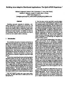
data processing latencies. It is also worth considering that design errors in the final application development stage are highly probable, even if there is detailed knowledge of the application area and the hardware platforms. Moreover, if an error is observed at that stage, the debugging is extremely hard and time-consuming. To address these challenges we propose a model-based design approach, in order to demonstrate the behavior and functionality of such applications. A model-based framework improves the quality, the modularity and reusability of the developed software artifacts. It further allows separation of concerns, in order to describe software and hardware architecture at a certain level of abstraction and apply modifications in them independently. Moreover, validation and verification are enabled in every development stage. The overall contribution of this work is the construction of a full-fledged design flow, based on a single semantic framework (BIP [1]), facilitating the rapid development of correct and functional sensor network applications. This flow supports application and system modeling, validation of functional correctness and performance analysis. It also permits automatic code generation in distributed sensor network platforms, leading to a significant reduction in the development time and errors of a manual implementation. The paper is organized as follows. Section II provides a brief introduction to the area and the current challenges of distributed sensor network applications. Section III presents the proposed design flow and details on its key steps. Section IV illustrates its use in a concrete WMSN application and Section V provides conclusions and perspectives for future work. II. S ENSOR NETWORK APPLICATIONS A major design factor in the development of sensor network applications is the communication, in order to exchange sensed data. As each network node is a resource-constrained device, the developed applications should have low bandwidth demands and tolerance to the communication latencies. Recently, the significant size reduction of inexpensive hardware, such as microphones and cameras, made the addition of audio and video capabilities for multimedia applications on a sensor network environment possible [2]. The development of such applications is mainly based on the increasingly popular lightweight versions of Linux, often referred to as embedded Linux [3]. This is because of their open-source environment and the support of several off-the-shelf platforms. Multimedia sensor network applications have strict timing constraints for data delivery and are extremely demanding in terms of memory and storage. Therefore, the usage of compression algorithms is necessary. Figure 1 illustrates such an application deployed over a wireless network for audio streaming and synchroniza-
tion of the local sensors’ clocks. Master Node
Slave Node
synchronize slaves
synchronize local clock
speaker
micro WiFi Slave Node synchronize local clock micro
Fig. 1: WMSN Application example The successful development of functional distributed sensor network applications depends on whether the following goals are ensured. Addressing functional and non-functional requirements. This goal focuses on the ability to identify and the methods to evaluate these requirements at design time [2]. On the one hand, non-functional requirements concern the optimal exploitation of the available hardware resources. Such requirements include the impact of the communication and computation delays as well as the packet delivery ratio (as an extent of the network connectivity) in resources, like memory usage or battery life. On the other hand, functional requirements involve the correctness and performance of the application. More specifically, they aim at managing buffer utilization and improving the efficiency of the compression algorithms for the multimedia. Occasionally, functional requirements are strongly affected by the non-functional, as described in [4]. Synchronization of the local sensors’ clocks (clock synchronization). In many applications the exchanged data needs to be accurately timestamped in order to be further processed. Nonetheless, this poses a serious application development problem, as the construction of a common time reference in a distributed system is hard to achieve. The solutions proposed to this problem have a common obtained synchronization accuracy in the microsecond scale. A traditionally adopted solution is the Network Time Protocol (NTP) [5], which nevertheless uses several trials to compute the average Round Trip Delay (RTD), resulting in less accuracy and increased resource consumption. As a result, it is suitable only for applications with low precision demands. A protocol that achieves high synchronization accuracy, even though it relies on the RTD calculation, is the Precision Time Protocol (PTP) [6]. However, the derived hardware enhancements (as in [7]) introduced to achieve microsecond accuracy may not be available in lightweight and resource-constrained environments. A new family of protocols for software-based clock synchronization is derived by applying the Kalman filter algorithm [8]. Compared to PTP, this family neither relies on the RTD calculation nor requires the interaction or the development of dedicated drivers to access the hardware, since it operates in the application level. The underlying Kalman filter algorithm tracks the advance of a reference clock and automatically adapts to it. Tools for application development and code debugging. As multimedia sensor network applications require the dense deployment of the small-scaled sensors, the communication latencies and the conflicts occurring in the protocol stack are unpredictable. Therefore, the probability of having design errors in the final development stage is extremely high. This happens due to the absence of separation of concerns so as
the application is developed independently from the hardware architecture. In this scope, a developer has to specify and build separate artifacts for the software and the hardware architecture, which can be also reused in other applications. Then, they should be able to define the optimal methodology for the deployment of the application on the given architecture so that it functions properly. This procedure is called mapping [9]. Meeting all the aforementioned goals is extremely demanding. A starting point to this challenge would be the availability of simulation and validation tools in the early development stage so as the system is validated beforehand and the design goals are ensured. Previous work in this scope is mainly divided in three categories. The first category targets specific sensor network operating systems [10] by using the Mathwork’s tools for modeling, simulation and automatic code generation. These tools are well known due to their vast variety of libraries, however they are not able to address functional and non-functional system requirements. Secondly, the metamodeling frameworks, addressing such requirements, use the UML tools to model and the Eclipse platform to generate code for sensor network applications [11]. Though certain developed frameworks ([12]) are also able to validate the previously mentioned requirements, they do not focus on clock synchronization and the generated code is usually not complete. Finally, formal modeling approaches for such applications provide validation support for functional and nonfunctional requirements [13] [14] as well as clock synchronization [15], but they do not implement tools for automatic code generation. Therefore, as far as knowledge is concerned, the existing work doesn’t take into account all the above design goals simultaneously. To this extent, in the following section we propose a novel method for the systematic development of distributed sensor network applications, enabling separation of concerns and targeting all their design goals. III.D ESIGN F LOW We hereby present our approach, based on a design flow, which leads to a framework for 1) the construction of a faithful sensor network system model for analysis as well as performance evaluation and 2) the generation of deployable code for applications in the domain of sensor networks. The design flow is based on the BIP framework 1 described below. BIP (Behavior-Interaction-Priority) [1] is a highly expressive, component-based framework with rigorous semantic basis. It allows the construction of complex, hierarchically structured models from atomic components, which are characterized by their behavior and interfaces. Such components are transition systems enriched with data. Transitions are used to move from a source to a destination location. Each time a transition is taken, component data (variables) may be assigned with new values, which are computed by user-defined functions (in C/C++). Atomic components are composed by layered application of interactions and priorities. Interactions express synchronization constraints and define the transfer of data between the interacting components. Priorities are used to filter amongst possible interactions and to steer system evolution so as to meet performance requirements, e.g. to express scheduling policies. A set of atomic components can be composed into a generic compound component by the successive application of connectors and priorities. BIP is supported by a rich toolset 1 http://www-verimag.imag.fr/BIP-Tools,93.html
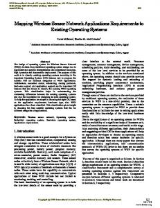
including tools that are used to check stochastic systems. This technique is called Statistical Model Checking (SMC) [16] and performs quantitative verification targeting functional and nonfunctional system requirements. Example 1: Figure 2 shows a graphical representation of one atomic component in BIP, which models the behavior of the PLL process (presented in Section III-A). Its behavior is described as a transition system with control locations idle, recvMsg, process and sndRes. The PLL component receives synchronization frames through the CLK RECV port. It subsequently moves from the idle to the recvMsg state. After an interaction through the port LOCAL CLK, it calculates a software clock through the internal port update and returns to the initial (idle) state. CLK REQ port is used to receive requests for calculating the local clock. The value of the local clock is calculated at the internal transition prepare and is exported through port CLK RES.
all the missing hardware dependent and network-specific information to the constructed abstract system model. 4) The performance analysis on the calibrated system model in BIP with the use of Statistical Model Checking (SMC). The results are used as a feedback to the user to propose enhancements in the design.
CLK REQ newFrame:=1
CLK RECV frame
idle
CLK RECV micReq:=1
recvMsg
LOCAL CLK
update [newF rame = 1] refClk:=Mclk+delay res:=pll clock in(refClk) LOCAL CLK
CLK RES
lclk
process prepare [micReq = 1] timeElapsed:=local clock-tUpdate Sclk:=pll get clock(res,timeElapsed)
sndRes
CLK REQ
CLK RES Sclk
Fig. 2: PLL component The BIP design flow, illustrated in Figure 3, uses PPM specifications (described in Section III-A) as a retargetable input model to: (1) automatically construct a sensor network system model in BIP and (2) automatically generate the code for execution on the target distributed sensor network platform. The proposed flow is used to evaluate functional, nonfunctional and clock synchronization requirements of sensor network applications. To achieve that, first, we apply SMC on the system model in BIP and second, we execute the generated code on the target sensor network platform. It is important to mention that the two paths, meaning the construction of the system model in BIP and the generation of executable code are consistent with each other. This is accomplished because both approaches integrally preserve the behavior of the input application software and the Sensor Network Components in BIP faithfully model the target sensor network. The proposed design flow proceeds in four main steps: 1) The construction of an abstract system model. This model represents the behavior of the application software running on the hardware platform according to the mapping, but without including all hardware dependent (e.g. execution times, data processing delays) and network-specific information (e.g. packet delivery ratio, end-to-end delays). 2) The generation of executable code that is deployed on the physical hardware platform. This is performed by initially developing code templates based on the input hardware specifications. Once these templates are fully constructed by the user, they can be reused for any sensor network application. They are subsequently parametrized, using node configuration files, in order to automatically generate the executable code. 3) The construction of the system model in BIP by injecting
Fig. 3: Proposed Design Flow A. Pragmatic Programming Model The Pragmatic Programming Model (PPM) is a description language developed to provide a simple and convenient way for describing highly-parallel applications expressed as networks of communicating processes. The language has been inspired by DOL (Distributed Operation Layer) [9], which is a framework devoted to the specification as well as the analysis of mixed software/hardware systems and provides a Kahn Process Network (KPN) model of the application. In PPM, application software is defined by using a process network model. It consists of a set of deterministic, sequential processes communicating asynchronously through shared objects, such as FIFOs, shared memories and mutexed locations. The process network structure in PPM is described by using XML specifications [4] and the process behavior is described using structured C code, with well defined communication primitives. Figure 4 presents an WMSN application in PPM, which is referring to the application described in Section IV. It consists of (1) one clock synchronization process synchro, sending out synchronization data through the FIFOs (SO1, SO3), and (2) two audio capturing processes micro, sending out audio data, through the FIFOs (SO2, SO4). The synchronization data is received by two processes PLL (implementing the clock synchronization protocol) and the audio data by an audio reproduction process speaker. SO1 synchro
PLL SO2
speaker
micro SO3 PLL SO4 micro
Fig. 4: WMSN Application PPM Model The mapping associates application software components to devices of the hardware platform, that is, processes to processors and shared objects to remote communication media. Specifications of the latter, including communication interface and protocols, are also described in the mapping to provide
all the necessary details for the code generation and the construction of the system model. The mapping in PPM is a XML description file, specifying how the application software is deployed on the target platform. As illustrated by the example of Figure 5 the application processes (“app-node” in XML) are bound to a hardware platform node (“hw-element” in XML).
Fig. 5: WMSN Application Mapping XML Description B. System model in BIP In our design flow we construct the system model in BIP to faithfully represent the behavior of the application running on the underlying hardware and network. The construction proceeds in two steps, as presented in the design flow. The first step is the construction of the intermediate abstract system model in BIP and the second step is the construction of the complete system model in BIP. The abstract system model in BIP is built in several steps. Firstly, the application software model in BIP is constructed by translating the PPM model. Secondly, HW specific components are constructed systematically from the characteristics of the sensor network platforms as well as the entities and communication mechanisms of the network protocols. Finally, the derived application software model is progressively enriched with the HW specific components, given a specified mapping. However, the derived abstract system model in BIP does not include all the hardware-dependent (e.g. execution times, data processing delays) and network-specific information (e.g. packet delivery ratios, end-to-end delays). The above information is injected to the model in the form of probabilistic distributions which are obtained by profiling techniques and execution of the generated code on the physical hardware platform. This technique is called calibration and results in obtaining the complete system model in BIP. To compute the probabilistic distributions, we analyze the debugging traces from the execution of the generated code on the hardware platform and extract all the necessary information for a distribution fitting procedure [17]. C. Code Generation The method used for automatic code generation is based on an infrastructure generating deployable code from PPM specifications. The generated code is portable and can be eventually deployed and run on any hardware architecture including sensor networks. Moreover, it consists of the functional code and the glue code. In the case of sensor networks, the functional code is generated from the application software in PPM, which consists of processes and shared objects. Processes are implemented as threads, and shared objects are implemented according to the underlying hardware architecture. Specifically, the threads are created and allocated to sensors in line with the process mapping, which also specifies configuration parameters for the employed communication protocols. The glue code implements the deployment of the application to the sensor network platforms and is obtained from the mapping. The generated code is described in C language. Both functional and glue code are implemented using retargetable
template files and sensor network hardware specific files. The tool is implemented in C++ and it consists of approximately 35 files and 11235 lines of code. IV. C ASE S TUDY: I NDUSTRIAL WMSN A PPLICATION We demonstrate our approach through a case study provided by an industrial partner (Cyberio 2 ) and illustrated in Figure 4. It targets on audio capturing and reproduction over a WiFi wireless network with the addition of clock synchronization. In this case, we focus on a sender-to-receiver synchronization, where the base station broadcasts periodically (period T=5s) a frame containing the hardware clock value (synchro process) to all the nodes through the wireless network. Each node applies a Phase Locked Loop (PLL [18]) synchronization technique, to construct a software clock. The construction is based on the Kalman filter algorithm (described in [4]). The PLL system takes the broadcasted clock as as an input and keeps the local clock synchronized to it. The expected synchronization accuracy for the particular case study, defined as the difference between the input and output clock, is specified as 1µs. The resulting clock is used by the micro process to timestamp the audio frames. Subsequently, the base station is able to reproduce the received audio frames through the speaker process in the correct chronological order. For the implementation of the WMSN application, we use a wireless sensor network that consists of three nodes. Each node is a UDOO platform 3 , which consists of a computational core, a WiFi card and a sound card. The computational core is responsible for the node’s processing operations, the WiFi card for the wireless communication of the network and the sound card for capturing or reproducing sound. The wireless network is supported by a Snowball SDK platform 4 used as Access Point (AP). To capture and reproduce audio samples, we used the API provided by the Advanced Linux Sound Architecture (ALSA) 5 . This API supplies structures and functions in order to communicate with the node’s sound card through the ALSA library. A. Code Generation on Distributed Sensor Network Platform In the deployed application, the clock synchronization protocol runs in parallel with an audio application. The synchro and speaker processes are mapped to the Master UDOO node, whereas the PLL and micro processes to the Slave UDOO nodes (see [4]). The shared objects are mapped to the WiFi cards, which manage the communication through the Snowball SDK AP. The sensor network nodes communicate by using User Datagram Protocol (UDP) through various modes, such as unicast, broadcast and multicast. We hereby present some experimental results obtained from the generated code for the case study. The results focus on the clock synchronization accuracy of a slave node. Specifically, in Figure 9 we plot the time difference between the Master and the software clock computed in the PLL process of the Slave, called synchronization error. The software clock follows the advance of the Master clock and maintains a relative offset from it (here around 100µs) with a resulting accuracy of 76µs. As illustrated in [18], in a PLL-based approach this offset depends on the synchronization frequency of the application. Although an increase of this frequency results 2 www.cyberio-dsi.com/ 3 http://www.udoo.org/features/ 4 http://www.calao-systems.com/articles.php?pg=6186 5 http://www.alsa-project.org/main/index.php/Main
Page
in better synchronization, it equally augments the number of transmitted packets in the network. This leads to higher energy consumption, thus shortening the network lifetime. The execution of the generated code has also provided 180
140 120 100
Master
Slave micro
speaker
80
AUDIO_SEND
READ
CLK_REQ
60
CLK_RES LOCAL_CLK
TICK
40 20
synchro
TICK
SEND RECV
Mclock 1000
RECV
Number of samples
WiFi
TICK
REQ
TICK
Sclock
CLK_RECV
Sbuffer
LOCAL_CLK
REQ
GET_CLK
CLK_REQ CLK_RES
Fig. 7: BIP abstract system model of the case study
100
Experiment 1: Buffer utilization. We evaluated the property of avoiding overflow or underflow in each buffer component by considering the following properties: φ1 = (SSbuf f er < M AX), as well as φ2 = (SM buf f er > 0), where SSbuf f er and SM buf f er indicate the size of the Slave and Master buffer components respectively. The value of M AX is considered as fixed and equal to 400. As illustrated in Figure 8 P (φ1 ) = 1 for the considered value of M AX, meaning that overflow in the SBuffer is avoided. Furthermore, the probability of underflow avoidance in the Mbuffer depends on the initial playout delay (p1 ). Specifically, in Figure 8 we can observe this for delays greater than 1430 ms P (φ2 ) = 1, meaning that the Master component should start the consumption of audio packets when this time duration has elapsed. ● ● ● ● ● ● ● ● ● ● ● ● ● ● ● ● ● ● ● ● ● ● ● ● ● ● ● ● ● ● ● ● ● ● ● ● ● ● ● ● ● ● ● ● ● ● ● ● ● ● ● ● ● ● ● ● ● ● ● ● ● ● ● ● ● ● ● ● ● ● ● ● ● ● ● ● ● ● ● ● ● ● ● ● ● ● ● ● ● ● ● ● ● ● ● ● ● ● ● ● ● ● ● ● ● ● ● ● ● ● ● ● ● ● ● ● ● ● ● ● ● ● ● ● ● ● ● ● ● ● ● ● ● ● ● ● ● ● ● ● ● ● ● ● ● ● ● ● ● ● ● ● ● ● ● ● ● ● ● ● ● ● ● ● ● ● ● ● ● ● ● ● ● ● ● ● ● ● ● ● ● ● ● ● ● ● ● ● ● ● ● ● ● ● ● ● ● ● ● ● ● ● ● ● ● ● ● ● ● ● ● ● ● ● ● ● ● ● ● ● ● ● ● ● ● ● ● ● ● ● ● ● ● ● ● ● ● ● ● ● ● ● ● ● ● ● ● ● ● ● ● ● ● ● ● ● ● ● ● ● ● ● ● ● ● ● ● ● ● ● ● ● ● ● ● ● ● ● ● ● ● ● ● ● ● ● ● ● ● ● ● ● ● ● ● ● ● ● ● ● ● ● ● ● ● ● ● ● ● ● ● ● ● ● ● ● ● ● ● ● ●
● ● ● ● ● ● ● ● ● ● ● ● ● ● ● ● ● ● ● ● ● ● ● ● ● ● ● ● ● ● ● ● ● ● ● ● ● ● ● ● ● ● ● ● ●
● ● ● ● ● ● ● ● ● ● ● ● ● ● ● ● ● ● ● ● ● ● ● ● ●
80 60 40 20
Probability(%)
●
● ● ● ● ● ● ● ● ● ● ● ● ● ● ● ● ● ● ● ● ● ● ● ● ● ● ● ● ● ● ● ● ● ● ● ● ● ● ● ● ● ● ● ● ● ● ● ● ● ● ● ● ● ● ● ● ● ● ● ● ● ● ● ● ● ● ● ● ● ● ● ● ● ● ● ● ● ● ● ●
●
●
● ● ● ● ● ● ● ● ● ● ● ● ● ● ● ● ● ● ● ● ● ● ● ● ● ● ● ● ● ● ● ● ● ● ● ● ● ● ● ● ● ● ● ● ● ● ● ● ● ● ● ● ● ● ● ● ● ● ● ● ● ● ● ● ● ● ● ● ● ● ● ● ● ● ● ● ● ● ● ● ● ● ● ● ● ● ● ● ● ● ● ● ● ● ● ● ● ● ● ● ● ● ● ● ● ● ● ● ● ● ● ● ● ● ● ● ● ● ● ● ● ● ● ● ● ● ● ● ● ● ● ● ● ● ● ● ● ● ● ● ● ● ● ● ● ● ● ● ● ● ● ● ● ● ● ● ● ● ● ● ● ● ● ● ● ● ● ● ● ● ● ● ● ● ● ● ● ● ● ● ● ● ● ● ● ● ● ● ● ● ● ● ● ● ● ● ● ● ● ● ● ● ● ● ● ● ● ● ● ● ● ● ● ● ● ● ● ● ● ● ● ● ● ● ● ● ● ● ● ● ● ● ● ● ● ● ● ● ● ● ● ● ● ● ● ● ● ● ● ● ● ● ● ● ● ● ● ● ● ● ● ● ● ● ● ● ● ● ● ● ● ● ● ● ● ● ● ● ● ● ● ● ● ● ● ● ● ● ● ● ● ● ● ● ● ● ● ●
0
debugging traces, which we analyzed, in order to compute probabilistic distributions for specific case study parameters. These parameters concern the computation of each device hardware clock, the packet delivery ratio and the end-to-end delays. The debugging traces were used to calibrate the BIP abstract system model and produce the BIP system model (design flow step 3), described in the following section. B. BIP System Model This section presents the system model constructed for the WMSN case study. It consists of the Master component and two instances of the Slave component, using the same interfaces and interactions with the other system components. For comprehension purposes, Figure 7 illustrates a simpler system containing only one instance of the Slave component. The Master transmits periodically synchronization packets through the port CLK SEND which contain its hardware clock value. This value as well as the Slave’s hardware clock value are computed using probabilistic distributions for their hardware clock model. The timing model is a discrete time step advance, associated with the interaction TICK. This interaction is used as a strong synchronization among all the system components, implementing a timing model. The transmitted and received packets are stored in a buffer component (Mbuffer and Sbuffer instances of Figure 7), which follows a FIFO queuing policy. The data processing is done by the WiFi component, modeling the wireless network, which also transmits packets to every Slave component in the model. This component is using probabilistic distributions for network-specific characteristics, such as the packet delivery ratio and the end-to-end delays. Whenever a synchronization packet is received by the Slave component (CLK RECV port), it computes the software clock. Hence, each audio packet is transmitted through the AUDIO SEND port and timestamped with the latest computed value of the software clock. A detailed description of the BIP system components from Figure 7 can be found in [4]. C. Analysis and experimental results We conducted two sets of experiments, focusing on equally important requirements in the development of multimedia sensor networks. The first analyzed the utilization of the buffer components concerning only the audio capturing and reproduction in the system. Thus, this experiment focused on a functional requirement, which is influenced by nonfunctional requirements such as the packet delivery ratio and the end-to-end delays. In the second experiment we focused
Mbuffer
CLK_SEND
Fig. 6: Synchronization accuracy (in µs) from the generated code
PLL RECV
RECV
SEND
1200
100
800
80
600
60
400
Probability(%)
200
20
0
● ● ● ● ● ● ● ● ● ● ● ● ● ● ● ● ● ● ● ● ● ● ● ● ● ● ● ● ● ● ● ● ● ● ● ● ● ● ● ● ● ● ● ● ● ● ● ● ● ● ● ● ● ● ● ● ● ● ● ● ● ● ● ● ● ● ● ● ● ● ● ● ● ● ● ● ● ● ● ● ● ● ● ● ● ● ● ● ● ● ● ● ● ● ● ● ● ● ● ● ● ● ● ● ● ● ● ● ● ● ● ● ● ● ●
0
100
200
0
0
40
Synchronization error (usec)
160
on the obtained clock synchronization accuracy. Therefore, we observed the difference between the Master clock (θM ) and the software clock computed in every Slave (θS ) without the impact of the audio capturing and reproduction. These requirements were described as stochastic temporal properties, using the Probabilistic Bounded Linear Temporal Logic (PBLTL) formalism [16]. Their probabilistic results, obtained using the SMC BIP tool, are accordingly presented.
300
400
500
600
size(Sbuffer)
700
800
900
1000
● ● ● ● ● ● ● ● ● ● ● ● ● ● ● ● ● ● ● ● ● ● ● ● ● ● ● ● ● ● ● ● ● ● ● ● ● ● ● ● ● ● ● ● ● ● ● ● ● ● ● ● ● ● ● ● ● ●
0
160
320
480
640
800
960
1120 1280 1440 1600
Initial playout delay (ms)
Fig. 8: Probabilities of φ1 (left) as a function of the Sbuffer size and φ2 (right) as a function of p1 (in ms) Experiment 2: Synchronization accuracy. The property of maintaining a bounded synchronization accuracy is defined as: φ3 = (|(θM − θS ) − A| < ∆), where A indicates a fixed offset between the Master and each computed software clock and ∆ is a fixed non-negative number, denoting the resulting bound. Initially, we used several probabilistic distributions from the execution results of the application to test if the expected bound ∆ = 1µs is achieved. However, as it can be depicted by Figure 9 the achieved bound by the simulations was always above the defined bound of 1µs for A = 100µs. We accordingly repeated the previous experiments, in order to estimate the best bound. Therefore, we tried to estimate the smallest bound which ensures synchronization with probability P (φ3 ) = 1, by repeating the previous experiment for a variety of ∆ between 10µs and 80 µs. The simulations have shown
that the synchronization bound was 76 µs, as it is also observed by the execution results of the generated code in Section IV-A.
[3]
180
[4] Synchronization error (usec)
160 140
[5]
120 100 80
[6]
60 40 20
0
200
400
600
800
1000
1200
Number of samples
[7]
Fig. 9: BIP system model synchronization accuracy (in µs) V. C ONCLUSION We have presented a novel approach, based on a design flow, facilitating the development of correct and functional distributed sensor network applications. This design flow takes as input the application software and the hardware specification (for the communication protocol and the sensor network platforms) as well as the mapping between them and constructs a system model in BIP. This model is executable, meaning that it can be tested, simulated and validated using the associated tools of the BIP toolset. Moreover, through the use of rapid prototyping, our approach supports the automatic code generation for the target sensor network platform. We illustrated the presented approach through a Wireless Multimedia Sensor Network (WMSN) application, used to evaluate functional and non-functional requirements through statistical model checking. It also exploits the advantages of the generated code for deployment on the target platform and for debugging purposes. The conducted experiments focus on buffer utilization and clock synchronization accuracy. As a future work, we are considering improvements in order to decrease the relative offset between the software clock, which is computed in each device, according to a reference clock. Thus, we are experimenting with various clock synchronization frequencies, whilst trying to keep the amount of packets in the network as low as possible. This may as well lead to a change of the clock synchronization protocol. Additionally, we focus on multimedia applications for environments supporting lower resource platforms than Linux. In this scope, Basu et al. introduced formal models for TinyOS, which is an evenly popular environment for the development of such applications, in [19]. Although supporting communication with lower resource consumption, such systems allow the transmission of a small amount of data in each packet. Therefore, in the target multimedia applications, data is often transmitted in several packets. Consequently, the network is more frequently occupied, resulting in a higher collision rate and packet losses. In order to analyze the impact of the additional latencies in the available resources, we plan to develop a similar design flow for such systems. R EFERENCES [1]
A. Basu, S. Bensalem, M. Bozga, J. Combaz, M. Jaber, T. Nguyen, and J. Sifakis, “Rigorous component-based design using the BIP framework,” IEEE Software, Special Edition from Routines to Services 28 (3), pp. 41–48, 2011. [2] S. Misra, M. Reisslein, and G. Xue, “A survey of multimedia streaming in wireless sensor networks,” Communications Surveys & Tutorials, IEEE, vol. 10, no. 4, pp. 18–39, 2008.
[8]
[9]
[10]
[11]
[12]
[13]
[14]
[15]
[16]
[17]
[18]
[19]
J. Hill, M. Horton, R. Kling, and L. Krishnamurthy, “The platforms enabling wireless sensor networks,” Communications of the ACM, vol. 47, no. 6, pp. 41–46, 2004. A. Lekidis, P. Bourgos, S. Djoko-Djoko, M. Bozga, S. Bensalem, “Design Flow for the Rapid Development of Distributed Sensor Network Applications,” Verimag Research Report, Tech. Rep. TR-2014-13, 2014. B. Sundararaman, U. Buy, and A. D. Kshemkalyani, “Clock synchronization for wireless sensor networks: a survey,” Ad Hoc Networks, vol. 3, no. 3, pp. 281–323, 2005. K. Lee, J. C. Eidson, H. Weibel, and D. Mohl, “IEEE 1588-Standard for a Precision Clock Synchronization Protocol for Networked Measurement and Control Systems,” in Conference on IEEE, vol. 1588, 2005. A. Mahmood, G. Gaderer, H. Trsek, S. Schwalowsky, and N. Kero, “Towards high accuracy in IEEE 802.11 based clock synchronization using PTP,” in Precision Clock Synchronization for Measurement Control and Communication (ISPCS), 2011 International IEEE Symposium on. IEEE, 2011, pp. 13–18. B. R. Hamilton, X. Ma, Q. Zhao, and J. Xu, “ACES: adaptive clock estimation and synchronization using Kalman filtering,” in Mobile Computing and Networking, 2008, p. 152–162. L. Thiele, I. Bacivarov, W. Haid, and K. Huang, “Mapping Applications to Tiled Multiprocessor Embedded Systems,” in Proceedings of the Seventh International Conference on Application of Concurrency to System Design, ser. ACSD ’07. Washington, DC, USA: IEEE Computer Society, 2007, pp. 29–40. [Online]. Available: http://dx.doi.org/10.1109/ACSD.2007.53 M. M. R. Mozumdar, F. Gregoretti, L. Lavagno, L. Vanzago, and S. Olivieri, “A framework for modeling, simulation and automatic code generation of sensor network application,” in Sensor, Mesh and Ad Hoc Communications and Networks, 2008. SECON’08. 5th Annual IEEE Communications Society Conference on. IEEE, 2008, pp. 515–522. T. Rodrigues, P. Dantas, F. C. Delicato, P. F. Pires, L. Pirmez, T. Batista, C. Miceli, and A. Zomaya, “Model-driven development of wireless sensor network applications,” in Embedded and Ubiquitous Computing (EUC), 2011 IFIP 9th International Conference on. IEEE, 2011, pp. 11–18. B. Akbal-Delibas, P. Boonma, and J. Suzuki, “Extensible and precise modeling for wireless sensor networks,” in Information Systems: Modeling, Development, and Integration. Springer, 2009, pp. 551–562. L. Samper, F. Maraninchi, L. Mounier, and L. Mandel, “GLONEMO: Global and accurate formal models for the analysis of ad-hoc sensor networks,” in Proceedings of the first international conference on Integrated internet ad hoc and sensor networks. ACM, 2006, p. 3. S. Tschirner, L. Xuedong, and W. Yi, “Model-based validation of QoS properties of biomedical sensor networks,” in Proceedings of the 8th ACM international conference on Embedded software. ACM, 2008, pp. 69–78. F. Heidarian, J. Schmaltz, and F. Vaandrager, “Analysis of a clock synchronization protocol for wireless sensor networks,” Theoretical Computer Science, vol. 413, no. 1, pp. 87–105, 2012. S. Bensalem, M. Bozga, B. Delahaye, C. Jegourel, A. Legay, and A. Nouri, “Statistical Model Checking QoS properties of Systems with SBIP,” in Leveraging Applications of Formal Methods, Verification and Validation. Technologies for Mastering Change. Springer, 2012, pp. 327–341. A. Nouri, M. Bozga, A. Molnos, A. Legay, and S. Bensalem, “Building faithful high-level models and performance evaluation of manycore embedded systems,” in Formal Methods and Models for Codesign (MEMOCODE), 2014 Twelfth ACM/IEEE International Conference on. IEEE, 2014, pp. 209–218. F. Ren, C. Lin, and F. Liu, “Self-correcting time synchronization using reference broadcast in wireless sensor network,” IEEE Wireless Commun., vol. 15, no. 4, pp. 79–85, 2008. A. Basu, L. Mounier, M. Poulhies, J. Pulou, and J. Sifakis, “Using BIP for Modeling and Verification of Networked Systems–A Case Study on TinyOS-based Networks,” in Network Computing and Applications, 2007. NCA 2007. Sixth IEEE International Symposium on. IEEE, 2007, pp. 257–260.