May 1, 2008 - Benedikt et. al. present VeriWeb, a dynamic navigation testing tool for web appli- cations [6]. VeriWeb starts at ... web browser URL box. This poses security ... future if we extend AutoDBT to performance testing. A recent paper ...
Building Test Cases and Oracles to Automate the Testing of Web Database Applications Lihua Ran, Curtis Dyreson, Anneliese Andrews, Ren´ee Bryce, 1,2,3,4 and Christopher Mallery 5
Abstract Many organizations rely on web applications that use back-end databases to store important data. Testing such applications requires significant effort. Manual testing alone is often impractical, so testers also rely on automated testing techniques. However, current automated testing techniques may produce false positives (or false negatives) even in a perfectly working system because the outcome of a test case depends on the state of the database which changes over time as data is inserted and deleted. The Automatic Database Tester (AutoDBT) generates functional test cases that account for database updates. AutoDBT takes as input a model of the application and a set of testing criteria. The model consists of a state transition diagram that shows how users navigate pages, a data specification that captures how data flows, and an update specification that shows how the database is updated. AutoDBT generates guard queries to determine whether the database is in a state conducive to performing and evaluating tests. AutoDBT also generates partial oracles to help validate whether a back-end database is updated correctly during testing. This paper describes the design of AutoDBT, a prototype implementation, several experiments with the prototype, and four case studies. Key words: Software testing, Database modification, Web applications, Functional testing
1 Introduction
Web applications are increasing in importance as consumers use the web for a wide range of daily activities. Though web applications differ widely in their functionality and in the technologies used in their implementation, these applications share 1 2 3 4 5
Schweitzer Engineering Labs, Pullman, WA Department of Computer Science, Utah State University Department of Computer Science, University of Denver Department of Computer Science, University of Nevada, Las Vegas School of Electrical Engineering and Computer Science, Washington State University
Preprint submitted to Elsevier Science
1 May 2008
the basic, simple architecture depicted in Figure ??. The figure shows a web application that users interface with through a set of (HTML) forms. A web application may collect data from users through forms and store it in an application database (AD). Several methods exist to test web applications (see Section 3) but current testing methods do not adequately test web application databases. As a simple example, consider the testing of a car reservation system. Suppose that we evaluate a test that makes a new car reservation. If the test is successful, it will reach the “Reservation Confirmed” page. However, if we immediately re-run the test, it may fail due to the state of the database. The reservation from the previous test case needs to be deleted before the second test executes. Relatively little attention has been given to developing systematic techniques for assuring the correctness of the interactions between a database management system (DBMS) and a web application, although substantial effort has been devoted to ensuring that the algorithms and data structures implemented in a DBMS work efficiently and protect the integrity of the data [35,36]. Given the critical role of web applications, there is a need for new approaches to assess their quality. This paper presents a framework, the Automatic Database Tester (AutoDBT), for the functional or black-box testing of a web database application. Functional testing evaluates the correctness of an application by judging whether the application passes or fails select test cases. The judge is called an oracle since it incorporates a prediction of how the application should perform. We extend an approach to perform functional testing of web applications to include the interaction of the application with a database [1,29]. Additional problems that emerge from this interaction include: • Persistent state - The state of a database is the data stored in the database as of some point in time. The state changes over time as users modify data. Users can execute a database transaction which is a sequence of data insertions, deletions, and/or modifications. Each transaction changes the state of the database. During testing of a web application, each test may modify the state of the database. This makes it difficult to know the state of the database a priori. • Choosing test data - Each test case needs to contain data to drive the test. When testing an in-memory application, test data can be generated prior to test case evaluation. Some tests are based on data that must be present in a database (e.g. a test to modify an existing car reservation needs that reservation to be in the database prior to the test) while other tests require that the same data be absent (e.g. a test to create a car reservation demands that the reservation be new to the database). • Correctness of database updates - As the application executes, it updates the database. How can we model and determine if the web database application correctly updates the database? 2
In this paper we present the AutoDBT framework to address the above problems as follows: • Persistent state - AutoDBT automatically generates a guard for each test case. The guard determines whether the test can be performed given the current state of the database [38]. It can be thought of as a precondition for the test. • Choosing test data - AutoDBT distinguishes between data that should be drawn from the application database and data that is not present in the application database which should instead be chosen from a database of synthesized test data. • Correctness of database updates - AutoDBT allows a software tester to specify, at a high-level, the database updates associated with each page transition. An oracle reports on the correctness of a software test. An in-memory web application passes a test if it reaches an expected final state (i.e. at the expected page). For a web database application, however, the expected final state also has to include the correct state of the database. AutoDBT automatically generates an oracle that partially determines whether an application correctly updates its database. Since the database can be quite large and it is infeasible to test the entire database state, the oracle can only test a small part of the database, hence the oracle is a partial oracle rather than a full oracle. This paper extends our previous work to more fully describe AutoDBT [29]. We show that we can model every kind of database transaction and examine several case studies. The paper is organized as follows. The next section illustrates a need for the AutoDBT framework. Section 3 reviews related work in the areas of database technology and web application testing. After that we present the details of AutoDBT. Section 5 provides an overview of AutoDBT, including a discussion of how to model the page navigation, specify the input data in each transition, and model database updates. Section 6 outlines the testing process. Section 7 discusses the ability of AutoDBT to model general kinds of database updates. The remaining sections describe implementation and several case studies that show that the additional cost of modeling the database is reasonable. Finally, the paper concludes and presents ideas for future work.
2 Motivating Example
This section presents part of a web application that illustrates the need to test database transactions in web applications. Consider an Online Car Rental System (OCRS). The main page is shown in Figure 1(a). Buttons on this page enable a customer to make a new reservation, view a current reservation, and modify or cancel an existing reservation. When a user activates one of these buttons, they move to a new screen. For instance, when a user activates the “Modify Reservation” button in Figure 1(a), a new page displays as shown in Figure 1(b). The modify reservation page has three text input boxes: First Name, Last Name and Confirmation Num3
ber. After the user enters their data and activates the “Continue” button, they are taken to a page (Figure 1(c)) where they can enter a Pickup Date, a Return Date, and a Car Type for their reservation. The page allows a user to update their car reservation data. After activating the “Confirmation” button, the updated reservation information displays as in Figure 1(d). This process can terminate at any time by activating the “Cancel” or “Back to Main Page” button. Activating these buttons transfers the customer to the main page (Figure 1(a)). The Cancel Reservation branch operates in a similar fashion. When a user activates the “Cancel Reservation” button, they are led to a new page as shown in Figure 1(e). After entering the confirmation number and activating the “Cancel Reservation” button on this page, the Cancelation Notification page is reached as shown in Figure 1(f). If the “Cancel Another Reservation” button is activated, the customer is transferred back to the page of Figure 1(e). The cancelation process can terminate at any step by activating the “Back to Main Page” button. Back to Main Page Cancel
(c)
Cancel
(b) Modify Reservation
Online Car Rental System
Modify Reservation
(d)
Select Date
Reservation Information
Pickup Date Return Date Continue Select Car Type
First Name Last Name Confirmation #
................ Confirmation
Cancel
Continue
Confirmation
Make Reservation
................ ................
Car Type Cancel
Back to Main Page
Make Reservation
(a)
View Reservation
View Reservation
Modify Reservation Cancel Reservation
(e)
(f) Cancellation Notification
Cancel Reservation Cancel Reservation
Cancel Reservation
Confirmation # Cancel Reservation
Back to Main Page
................. ................. ................. Cancel Another Reservation
Back to Main Page
Cancel Another Reservation
Back to Main Page Back to Main Page
Fig. 1. The Online Car Rental System (OCRS)
One feature of some web database applications such as the OCRS is the frequent interaction between customers and an application database. An important component to testing this type of application is verifying whether the database correctly updates in response to customer input. For instance, in the previous example, a customer provides required information through the GUI in Figure 1(b) and changes data in Figure 1(c). After clicking the “Confirmation” button, the database should update the reservation. Testing needs to ensure that the application database successfully updates. Testing the OCRS is complicated because it interacts with a database that could have a large amount of critical data, i.e. an upgrade is tested several months after the OCRS has been “live.” It may be difficult or impossible to start each test with a clean, empty database. Furthermore, some tests will require particular data to be present in the database, i.e. a test of the “Modify Reservation” functionality needs to have a reservation in the database. The application database has to be checked prior 4
to running a test case to determine if the database is in a state that is conducive to performing the test. Finally, when the OCRS modifies the database, it is important to test whether the database correctly updates. It is generally not feasible to store the state of the database prior to the test, and compare it to the state after the test, since storing and comparing two copies of a large database for each test in a large test suite can be prohibitively expensive.
3 Related Work
Several techniques exist to test web applications. Simple tools check links, validate HTML code, and measure performance. (See [16] for a list of tools.) Playback tools indirectly support functional validation as testers can record test sequences for future replay. While these support testing, they are static validation and measurement tools, none of which provide functional testing on their own. Generating and selecting tests is still an open issue. A number of techniques exist to test different aspects of web applications. Di Lucca et. al. provide a model and tools that address unit and integration testing of web applications where single pages of the web application are the components to test at the unit level [10]. Test cases exercise functional requirements. While test cases are automated, input generation is not. Ricca and Tonella develop a tool that creates a UML model from pages of a web application and then generates test cases, each test case being a sequence of URLs [30]. The model is based on static HTML links and does not cover dynamic aspects needed to cover all possible paths in dynamic websites. Again, users need to provide input values. Liu et. al. develop a Web Application Test Model (WATM) that generates test cases based on data flow interactions within objects, between objects, and across clients [24]. Kung, Liu, and Hsia [19,20] develop a test generation method based on multiple models of the applications under test. The models include Object Relation Diagrams, Object State Diagrams, a Script Cluster Diagram, and a Page Navigation Diagram. This model assumes that the source is available, whereas our approach does not. Also, this paper uses an enhanced Finite State Machine that includes representation of test constraints and does not need multiple types of diagrams. Unlike Kung et al., we also represent the FSM via logical, rather than physical web pages and solve potential state space explosion problems through partitioning and a different approach towards input description on the edges of the FSM. Lee and Offutt [23] describe a system that generates test cases using a form of mutation analysis. They focus on validating the reliability of data interactions among web-based software components. Specifically, they consider XML-based component interactions. This approach tests web software component interactions, whereas our current research focuses on the web application level. 5
Yang et al. [39,40] present an architecture for tools that test web applications. The architecture consists of five subsystems including test development, test measurement, test execution, test failure analysis, and test management. From the paper, it is not clear whether the test architecture includes new tools or whether it is meant to incorporate existing tools. The FSM modeling-based tool proposed in [1] satisfies the test development and test measurement portion of the test architecture. Jia and Liu [18] propose an approach that formally describes tests for web applications using XML. They develop a prototype tool, WebTest. Their XML approach could be combined with the test criteria proposed in [26] by expressing the tests in XML. Benedikt et. al. present VeriWeb, a dynamic navigation testing tool for web applications [6]. VeriWeb starts at a given URL and explores sequences of links in web applications by nondeterministically exploring action sequences. Excessively long sequences of links are limited by pruning paths in a form of path coverage. VeriWeb creates data for form fields by choosing from a set of name-value pairs that are initialized by the tester. VeriWeb is the most similar work to the ideas presented in [1]. The primary difference is in the graphs and reduction techniques. Our approach differs as we rely on extended FSM models of the web application and use aggregation abstraction of the extended FSMs to control the size. Bypass testing is a complementary technique to those previously described. Users may bypass client-side checking by typing GET and POST requests directly into a web browser URL box. This poses security concerns. Offutt et. al. provide examples of popular web applications that use client-side checking, showing that such testing is important [28]. Bypass testing is a technique that does not require access to source code. User-session-based testing is another approach that does not require access to source code. In user-session-based testing, test cases are actual user-sessions as recorded in web logs. Elbaum et. al. leverage user-session data for test cases and conclude that user-session-based testing can be more effective than test cases based on white-box techniques, but the techniques are complementary as they detect different faults [11]. Further, more tests usually find more faults. However, in practice, a large number of user-sessions may accumulate for popular web applications. Sampath et. al. develop reduction techniques for user-session-based testing that maintain coverage of all base case requests and use case representation while maintaining effective fault detection capabilities [32,34]. A different approach to managing large usersession-based test suites is to prioritize the test cases. Sampath et. al. provide case studies that show that prioritization by parameter-value interactions and frequency based metrics are useful [31]. Further Alshahwan and Harman present an approach to automatically repair existing regression test cases for web applications [2]. Halfond and Orso provide an automated technique for discovering web application 6
interfaces [15]. In comparison to a web crawler approach, their approach identifies more interfaces in several case studies. Their future work may use user-sessionbased test cases which inherently contain legal inputs. Testing techniques for the database aspect of web applications are limited. Hsu et. al. develop the HED model, which is particularly useful for maintenance of web applications [17]. Web applications may distribute application logic between hundreds of files. Modifications to such files can impact stored data, as can changes to the database itself. The HED model identifies files impacted by modifications to a program through structure and database analysis. Deng et. al. use path-based test case generation for database web applications where each test case contains a sequence of pages to visit and the input values for each page [9]. To generate tests, they (1) differentiate static and data-based pages, (2) build an application graph, (3) identify paths through the graph, (4) generate inputs, and (5) execute test cases. A particularly novel aspect of their work is that they use the AGENDA tool to populate the web application database based on sample values and expected behaviors that users provide. Our work differs from their work as we provide guard queries, consider the state of the database during test execution, and provide a partial test oracle. Indeed, these are serious concerns for automated testing. Previous database testing research exists for techniques that automatically populate a database with synthetic data for testing purposes [7,14]. These approaches are complementary to our research in modeling and testing the interaction of a web application with a database. Database benchmarks like TPC are popular for assessing the performance of DBMSs [35,36]. However, DBMS benchmarks aren’t useful for functional testing of database applications, though they could play a role in the future if we extend AutoDBT to performance testing. A recent paper describes test coverage adequacy criteria in the testing of application databases [22]. Kapfhammer and Soffa point out that there are few tools to support testing of database applications; and that applications with databases have an additional set of testing problems not found in non-database applications. Similar to AutoDBT, they focus on using data flow specifications to generate test cases. Unlike our approach, they do not perform black-box testing. They “instrument” the code for the database and application. In contrast, we focus on black-box testing that does not modify application code. Additionally, Willmor and Embury [38] investigate the concept of guard queries. Finally, Sprenkle et. al. provide automated oracle comparators for web applications [33]. Their approaches verify that the HTML-based output of a test case is correct. They suggest that validating the application’s database state may be a useful extension as many web applications use a back-end database. Our oracle focuses on database issues. 7
4 Testing a Web Database Application
This section presents an abstract framework for testing a web database application; the next section presents AutoDBT in more detail, making this abstract framework concrete. In general, testing a web database application is different than testing an in-memory web application because of the ever-changing state of the application database. The application database changes state as users insert, delete, and modify data during testing. Because of the changing database, an individual test case might not be able to run in some database states. For instance, a test case to check a confirmed reservation needs the reservation to exist in the database. In this section, we first present an overview of testing an application without a database, and then cover testing of a web database application.
4.1
Testing an In-Memory Web Application (without a Database)
At an abstract level, a web application consists of a network of transitions as shown in Figure 2. A transition begins at a source web page, Psrc , which is usually an ¯ from the form, the application makes a tranHTML form. Upon receiving input, I, sition to some destination page or form, Pdstk . The destination page depends upon ¯ So each transition of a web application can be considered as a function, W , that I. computes a destination page from a source page and some input; so the signature of W is P × I¯ → P . Psrc
W
Input, I
(The application transition function)
Transition Pdst1
Pdst2
…
Pdstk
Possible destination pages (forms)
Fig. 2. A transition in a web application
In black box testing, a test designer first builds a model of the each transition, called the specification model, which captures the desired behavior of the web application. Testing examines whether the application correctly implements the specification. If ¯ the implementation produces the starting from a web page Psrc and given input, I, same destination web page, Pdst , as the specification, then the implementation is deemed correct. In testing, I¯ is called a test case, while Pdst is the corresponding oracle. 8
Before testing begins, a test coverage criterion is given that describes the range of testing to be performed, i.e. which behavior of the web application to test. For instance, according to a given test coverage criterion, the testing target may be the sequence of forms P0 , . . . , Pm . In order to drive a test along the specified transition sequence, each input I¯ needs to be chosen to ensure that the implementation proceeds along the desired sequence. 4.2
Testing a Web Database Application
Many web applications have a back-end application database (AD). The testing of a web database application needs to: • • • •
determine whether the database is in a state that allows the test to proceed, compute the page transition depending on the state of the application database, add data which is not in the application database to a test case, and test whether the database is in a correct state after the test updates the database.
A transition of a web database application can be modeled as a function that includes data stored in the application database as shown in Figure 3. A transition begins at a source web page, Psrc , and the initial state of the application database, ¯ the application transitions to some destination ADsrc . Upon receiving input, I, page, Pdsti , and updates the database to some state ADdsti . The destination page and database state depends upon I¯ and the initial state of the AD. So each transition of a web application can be considered as a function, WD , with the signature P × I¯ × AD → P × AD. Psrc
Input, I
WD ADsrc
(The application transition function)
Transition … Pdst1
ADdst1
Pdst2
ADdst2
…
Update Pdstk
ADdstk
Possible destination pages (forms) and database states
Fig. 3. A transition in a web database application
In black box testing, a test designer first builds a model of each transition and database update. A database update specifies how the database will change, i.e. which insertions, deletions, or modifications to make in a transition. Testing determines 9
whether the implementation matches the behavior predicted by the model, which for the database tests the correctness of database updates, that is, does state ADdsti in the model match the corresponding state in the implemented AD? While it is infeasible to enumerate the space of potential correct database states for a transition, we can use the update specification associated with a transition to predict the small amount of data that is changed during a transition and test the database after the transition to determine whether the change was effected. We call this prediction an oracle and we show in this paper how to create an oracle to partially test for a successful update. ¯ needs to drive the testing process in a direction specified by a given A test case, I, test coverage criterion. The input for a web database application comes from the AD when existing data is required, but sometimes new data, which is different than data in the AD, is necessary. We introduce the synthetic database (SD) to store the new data. The synthetic database and application database are disjoint, that is they have different data.
5 AutoDBT
This section describes the AutoDBT framework for testing a web database application. We present an overview of the architecture first and then describe each component in the architecture.
5.1
Overview
AutoDBT is a framework for testing web database applications. The framework is depicted in Figure 4. AutoDBT has three main steps. The first step specifies the expected behavior of the application as a Database Extended Finite State Machine (DEFSM). A modeler develops a DEFSM specification for the web application. The top-most component of Figure 4 shows that the DEFSM consists of two parts: a state transition diagram and a data specification. The state transition diagram is a directed graph that models the user navigation between forms in the interface (see Figure 5). Each edge in the graph has a label for each unique transition. The data specification articulates input constraints and database updates associated with each transition in the state transition diagram. In the second step, the Test Sequence Generator automatically generates a set of test sequences. A test sequence traces a path in the DEFSM. The test coverage criteria dictate the range of test sequences to generate. Meanwhile, a Dynamic Data Specification Generator automatically generates a dynamic data specification based on the data specification given in the first step. The dynamic data specification captures how the application database updates during evaluation of a test. The third step performs the testing process 10
which takes as input the dynamic data specification, the generated test sequences, data sources, and test data selection criteria, to generate a report on the test result. The remainder of this section illustrates the framework using the OCRS example. Section 6 the describes how to execute the testing process. DEFSM Modeling State Transition Diagram
Test Coverage Criteria
Data Specification
Test Sequence Generator
Dynamic Data Specification Generator
Test Sequences
Dynamic Data Specification
Data Sources
Testing Process
Report
Fig. 4. AutoDBT’s framework
5.2
Using a Finite State Machine
FSMs are a tool for characterizing the transitions of a web application function. Finite state machines (FSM) provide a convenient way to model software behavior independent of an actual implementation. Several methods for deriving tests from FSMs exist [8,13,27]. Theoretically, FSMs can completely model web applications, however, even simple web pages can suffer from the state space explosion problem. Web pages may contain a large variety of possible inputs and choices as to the order in which to enter information. Factors such as these suggest that a finite state machine can become prohibitively large, even for a single page. Thus, an FSM-based testing method can only be useful if techniques to generate FSMs are descriptive enough to yield effective test suites yet small enough to be practical. FSMWeb, addresses the state explosion problem with a hierarchical collection of aggregated FSMs [1]. The bottom level FSMs are formed from web pages and parts of web pages called logical web pages. The top level FSM represents the entire web application. Application level tests combine test sequences from lower-level FSMs. Our approach extends FSMWeb to test web application databases. We introduce a DEFSM to model the behavior of a web database application next. 11
Definition 5.1 [DEFSM] A DEFSM is �S, s0 , ADs, AD0 , V, T � where each component is defined as follows. • S is a finite set of web states which correspond to the logical web pages. • s0 is the initial web state or logical web page. • ADs is a finite set of the associated back-end application database (AD) states. The schemas of all elements of the ADs are the same: AD (R1 , . . . , Rn ), where R1 , . . . , Rn are relations 6 in the AD. The schema of relation Ri is the form: Ri (A1 , . . . , Am ) where Aj , 1 ≤ j ≤ m denotes the j th attribute of relation Ri . However the state (instantiation) of each element of the ADs is unique. • AD0 is the initial AD state. • V is a set of variables which denote all possible web page input parameters. • T is a set of state transitions. Each t ∈ T is a quadruple �Ssrc , Sdst , P (Vt ), Updatet � that obeys the following conditions. · Ssrc , Sdst ∈ S, they are the source and destination web states of transition t respectively. · Vt = (Vt0 , . . . , Vtj ) (Vti ∈ V, 0 ≤ i ≤ j) is the list of input variables of transition t. If a variable Vti has a value, then the value is inherited. P (Vt ) is a predicate expressed in terms of Vt that defines the evaluation of the variables of Vt . Our approach defines, P (Vt ) as a Prolog rule in Section 5.3.2. · Updatet consists of a sequence of database update operations including insertions and deletions. It is defined as Prolog rules in Section 5.3.2. At state Ssrc , for an instantiation of Vt , if P (Vt ) evaluates true, the web state changes to Sdst , while the database state transfers from ADsrc to ADdst (ADsrc , ADdst ∈ ADs ) in response to the Updatet . If there is no update, ADsrc = ADdst .
5.3
DEFSM Modeling
The first step in using AutoDBT is to model the page navigation with a DEFSM. Part of the DEFSM is a state transition diagram that captures the expected behavior of a given web application at an abstract level. We assume that the modeler building the DEFSM has a thorough knowledge of the requirements and behavior of the application.
6
A relation is the basic structure in the most popular model for databases: the relational model. Informally a relation is a table in a relational database. Mathematically, a database relation is finite sets of tuples; a relation in mathematics is a subset of the cartesian product of N domains. Informally a tuple is a row in a table.
12
Main 1
2
3
9
13
8
9’
MK
MD 1
3’
C1
V 12
5’
4
MD 2
5
11
10
C2
7
6
MD 3
Fig. 5. OCRS’s state transition diagram
5.3.1
State Transition Diagram
The state transition diagram is a directed graph in which each node represents a (logical) web page and each edge represents a possible page transition (button or hyperlink). Figure 5 gives the diagram for the OCRS. In this paper we focus only on the Modify Reservation and Cancel Reservation paths shown in Figure 5. In this diagram, the web application begins in the Main state. There are four paths that emanate from the Main state. Through transition 2, the application transfers to state (MD1 ) of the Modify Reservation path, then through transition 4 to state MD2 , and finally through transition 6 to state MD3 . At each of these three states (MD1 through MD3 ), the application can transfer back to the original Main state by transition 3, 3� , 5, 5� , or 7, respectively. Usually, each state corresponds to an entire web page or form, but more specifically a state represents a group or part of a page devoted to a specific function. The transitions of other functional paths can be similarly explained. The OCRS is a relatively simple application and a single state transition diagram suffices. For complex applications, we allow “nested” [3] transition diagrams. That is, simple FSMs can be nested as states in other FSMs [1].
5.3.2
Data Specification
A modeler specifies how data flows in the application, especially between the application and database. For each transition of the DEFSM, the modeler gives constraints on the input (the input specification) and sketches the correctness criteria for the output. Since the output correctness criteria depend on how the database updates, the expected updates are modeled as well (the update specification). AutoDBT adopts a declarative approach for data specification, and expresses database updates and input constraints in Prolog. We choose Prolog because it offers welldefined declarative semantics for expressing database queries. We use Prolog rather 13
than Datalog because we generally need to evaluate our queries using a top-down, tuple-at-a-time evaluation technique, i.e. using Prolog’s evaluation model. In the remainder of this section, we illustrate how to specify the input and output in Prolog using the OCRS example. Web applications have many different kinds of input widgets. For simplicity, this paper focuses only on text boxes and buttons. We assume that the schemas of both data sources are known to the modeler before the testing process begins. We further assume that the schema of the synthetic database (SD) is the same as that of the AD. The input specification consists of two parts. The first part specifies the source of the test data. For a web database application, the input data can be drawn from two sources: the application database (AD) or the synthetic database (SD). The SD contains data that is not in the AD. For instance, if the customer’s last name, first name, and confirmation number are in the AD, a tester can run a test using this data for the page in Figure 1(b). However, if data is not available in the AD then the data should be chosen from an SD. The second part of the input specification captures the data flow on transitions in the DEFSM. Definition 5.2 [Input data flow specification] The input data flow specification for transition i is either a button name or a Prolog rule of the following form: inputi (Vi1 , . . . , Vin ) :- Predicate1 , . . . , Predicatem , Button. where • inputi is a predicate with a list of variables (Vi1 , . . . , Vin ) denoting all of the required input parameters of transition i; • the rule is safe which means all variables in the head appear in some predicate in the body, • Button represents the activation of a button to submit the input to the application; and • Predicate1 , . . . , Predicatem is a list of predicates of the following form: Database Relation(A1 , . . . , Ak ); or inputj (Vj1 , . . . , Vjk ). where · Database ∈ {AD, SD}; · Relation ∈ {R1 , . . . , Rn }; · Ai ∈ {constant, variable, ‘ ’} (1 ≤ i ≤ k), where constant ∈ domain of the ith column.
14
To help explain the input data flow specification, consider the OCRS example. Table 1 shows the specification for transitions of the Modify Reservation path and the Cancel Reservation path in Figure 5. According to the specification, on transition 2, a “Modify Reservation” button is required. On transition 4, the customer’s first name, last name, and the confirmation number of an existing reservation are required before a “Continue” button is activated. The DEFSM modeler uses Fn, Ln, C# to denote the required input. The Fn and Ln are chosen from the Customer relation while C# comes from the Reserves relation of the AD. The meaning of the input data flow specification for the other transitions can be similarly explained. Transition
Input Data Flow Specification
2
input2 () :- Button(Modify Reservation).
3
input3 (Fn, Ln, C#) :AD Customer(Fn, Ln, Cid), AD Reserves(Cid, C#), Button(Cancel).
3�
input3� (Fn, Ln, C#) :SD Customer(Fn, Ln, Cid), SD Reserves(Cid, C#), Button(Cancel).
4
input4 (Fn, Ln, C#) :AD Customer(Fn, Ln, Cid), AD Reserves(Cid, C#), Button(Continue).
5
input5 (Pd, Rd, Ct) :AD Reservation( , Pd, Rd, Ct), Button(Cancel).
5�
input5� (Pd, Rd, Ct) :SD Reservation( , Pd, Rd, Ct), Button(Cancel).
6
input6 (Pd, Rd, Ct) :SD Reservation( , Pd, Rd, Ct), Button(Confirmation).
7
input7 () :- Button(Back to Main Page).
8
input8 () :- Button(Cancel Reservation).
9
input9 (C#) :- AD Reservation(C#, , , ), Button(Back to Main Page).
9�
input9� (C#) :- SD Reservation(C#, , , ), Button(Back to Main Page).
10
input10 (C#) :- AD Reservation(C#, , , ), Button(Back to Main Page).
11
input11 () :- Button(Cancel Another Reservation).
12 input12 () :- Button(Back to Main Page). Table 1 Input data flow specification for the Modify and Cancel Reservation paths
The AutoDBT testing process requires both a populated AD and SD. Initially the SD is empty, while the AD may already contain data (if the web application has been running prior to testing). Since the testing process will change values in the AD, the AD should be copied prior to testing and the copy used for testing. The 15
SD must be populated with synthetic data for testing purposes. Gray et al. present several techniques to populate a database with synthetic data [14]. In particular they show how to quickly generate, in parallel, a large database that obeys certain statistical properties among the records. We populate our SD with randomly generated data since the synthetic data does not have to model “real-world” data, rather it only has to be data that is absent from the AD. Populated AD and SD tables for the OCRS are shown in Table 2 and Table 3, respectively. Available Car Type Reserves Customer FirstName john mike rick kate
LastName smith green reed brown
CarType CustomerID
Confirmation#
c0001
0001
c0002
0002
c0003
0003
c0004
0004
c0004
0005
CustomerID c0001 c0002 c0003 c0004
CarNumber
economy
50
compact
40
full size
60
minivan
45
luxury
20
convertible
30
Reservation Confirmation#
PickupDate
ReturnDate
CarType
0001
10/01/03
10/03/03
economy
0002
10/02/03
10/05/03
compact
0003
10/15/10
10/23/03
full size
0004
11/03/03
11/30/03
minivan
0005
11/03/03
11/30/03
full size
Table 2 An example application database (AD) Customer FirstName
LastName
franklin alicia
Reserves CustomerID
CustomerID
Confirmation#
bond
c0006
c0006
0006
wong
c0007
c0007
0007
Reservation Confirmation#
PickupDate
ReturnDate
CarType
0006
12/04/03
12/10/03
luxury
0007
12/06/03
12/08/03
convertible
Table 3 An example synthetic database (SD)
In addition to the input specification, the modeler also needs to specify how to update the database. This specification evaluates whether the application correctly updates the AD. There are three kinds of updates: insertion, deletion, and modification. We treat a modification as a deletion followed by an insertion. To model 16
deletions from AD Relation, we add a relation, delete AD Relation, that stores tuples that should be deleted. For insertions, we introduce insert AD Relation which buffers tuples that should be inserted. The schema of each relation is the same as that of AD Relation. In the update specification, the modeler gives a specification of what to delete or insert during an update. Table 4 shows the update specification for transitions of the Modify Reservation and Cancel Reservation paths. There is no update associated with most of the transitions so only a few of the transitions have update specifications. Transition 6 modifies the AD while transition 10 involves a deletion. The modification is modeled as a deletion followed by an insertion, so two rules are associated with transition 6. Transition 10 deletes a tuple from the AD Reservation relation. To maintain referential integrity, the tuple that has the deleted C# in the AD Reserves relation has to be deleted as well. Definition 5.3 [Update specification] The update specification is one or more Prolog rules of the following two forms. 1) delete AD Relation(A1 , . . . , An ) :Predicate1 , . . . , Predicatem . 2) insert AD Relation(A1 , . . . , An ) :Predicate1 , . . . , Predicatem . The form of each Predicatei is given in Definition 5.2. Transition
Update Specification
6
delete AD Reservation(C#, Pd, Rd, Ct) :input4 ( , , C#), AD Reservation(C#, Pd, Rd, Ct). insert AD Reservation(C#, Pd, Rd, Ct) :input4 ( , , C#), input6 (Pd, Rd, Ct).
10
delete AD Reservation(C#, Pd, Rd, Ct) :input10 (C#), AD Reservation(C#, Pd, Rd, Ct). delete AD Reserves(Cid, C#) :input10 (C#), AD Reserves(Cid, C#).
Table 4 The update specification for the Modify and Cancel Reservation paths
The modeler has to be careful when developing an update specification to associate updates only with transitions that reflect transaction commit points. In our example the database updates after each update transition, but in general the update could be delayed. Many web database applications support concurrent users. For instance, in the OCRS, many users can simultaneously make car reservations, and the reservation process might extend over several transitions. An application often packages the work done by a sequence of forms into a single transaction. A transaction is a logical unit of database processing that includes one or more database access 17
operations and it executes on an all-or-none basis. The transaction does not permanently record in the database until the transaction commits. Since the database state does not update until the transaction commits (which may span over multiple transitions), oracles should evaluate just after the commit.
5.4
Test Sequence Generator
Based on the state transition diagram, for any given test coverage criteria, we can automatically generate a test sequence. A test sequence is a sequence of transitions that describe which transitions to test and in what order. Common coverage criteria include testing combinations of transitions (switch cover) [8], testing most likely paths [37], and random walks [25]. Since the state transition diagram is a directed graph, well-known graph theory algorithms can efficiently generate test sequences automatically. An algorithm for the New York Street Sweeper Problem [4] generates a minimal length tour (that is a closed tour covering each link) for a directed graph [5]. This tour can represent a minimal length test sequence that starts and ends at an initial state, covering each transition of the testing target. For instance, this algorithm generates the following test sequence to test the Modify Reservation path. 2→3→2→3’→2 →4→5→2→4→5’ →2→4→6→7 5.5
Dynamic Data Specification Generator
A test sequence is a sequence of transitions. A test case is an instantiation of the input parameters for those transitions, i.e. it contains all of the data necessary to perform the test. A transition can modify the AD or SD. The input specification stipulates which database to use in choosing the test data while the update specification models the expected dynamic behavior in response to the input data. In this section, we describe how AutoDBT combines the input and update specifications to produce a dynamic data specification that captures this dynamic behavior. Before illustrating how to generate the dynamic data specification, we first introduce how the dynamic behavior of the database is captured. In our approach, the dynamic behavior is captured in an update list consisting of a buffer of deleted tuples and a buffer of inserted tuples. The update list for the AD, AUL, is [ADel, AIns] where ADel is the delete buffer and AIns is the insert buffer. The update list for the DS, SUL, is a buffer of deleted tuples [SDel]. A tuple is deleted from the SD when it is used (so that subsequent tests are unable to reselect the tuple, thereby ensuring that the data in the AD and SD remains disjoint). 7 7
Tuples are not inserted into the SD during testing, so an insertion buffer is not present in
18
Initially the AD/SD buffers are empty. For the AD, after each update transaction, the buffers are updated to capture the effects of a modification as follows. When a tuple is deleted, the tuple is inserted into the ADel buffer, unless it appears in the AIns buffer (as a result of a previous insertion in the evaluation of the test case) in which case it is simply removed from AIns buffer. Insertion is similar. If the update transaction contains more than one transition, then the update list will not change until the transaction commits. Based on the update specification given by the modeler, the updated AD and SD versions can always be derived from the initial version and the associated list. Each updated relation can be derived by applying the following Prolog rules. AD Relation(A1 , . . . , Ak , AUL) :AD Relation(A1 , . . . , Ak ), notdeleted(Relation(A1 , . . . , Ak ), AUL). AD Relation(A1 , . . . , Ak , AUL) :- inserted(Relation(A1 , . . . , Ak ), AUL). notdeleted(Fact, AUL) :AUL = [ADel, AIns], ¬ member(Fact, ADel). inserted(Fact, AUL) :AUL = [ADel, AIns], member(Fact, AIns). The first rule and the third rule are related. The first rule says that a particular version of an AD Relation with an associated update list (AUL) can be derived by including all of the tuples in the initial version that have yet to be deleted while the third rule checks that those tuples are members of the ADel list. The second rule adds all of the tuples that have been inserted in AD Relation, or have been re-inserted after being deleted. The fourth rule checks whether a particular tuple is a member of the AIns list. Similarly, the Relation of updated SD versions can be derived by applying the following rule. SD Relation(A1 , . . . , Ak , SUL) :SD Relation(A1 , . . . , Ak ), ¬ member(Relation(A1 , . . . , Ak ), SUL). The dynamic data specification generator takes in both the input and update specification. It generates a dynamic data specification which consists of two components: a dynamic input specification (DIS) and a data inheritance graph (DIG). The DIS expresses both how the input data should be generated, and also how new versions of the AD and SD are generated as the database is updated. The DIG captures how data flows from one transition into another. In the following two sections, we outline how the two components are generated. the SUL.
19
5.5.1
Data Inheritance Graph Generation
As a test navigates from page to page, input for a form in one transition may flow into a later transition. For instance, the update rule for transition 6 in Table 4 uses a confirmation number, C#, from the input4 fact produced in the evaluation of the input rule associated with transition 4 in Table 1. The data inheritance graph (DIG) is a collection of these dependencies. The graph can be automatically generated by analyzing the input and update specifications. In the OCRS example, the graph consists of nodes for transitions 4 and 6 and one edge from 4 to 6, labeled with C#.
5.5.2
Dynamic Input Specification Generation
The DIS specifies how to create new versions of the database in response to user inputs and database updates. Modeling database changes are important for testing the correctness of a database update. The DIS merges the input and update specifications. One rule is added to the DIS for each rule in the input specification. The DIS rule is constructed in two steps as follows. (1) Generate the head: The head of the DIS rule is derived from the head of the input rule by modifying it to include the current AD version (captured by the list of updated tuples AULin ) and the next version of the AD (denoted as AULout ). For the SD, SULin and SULout are used. In addition, for every variable inherited by this transition in the DIG, add the variable to the head. For example, the head of the input rule for transition 6 is input6 (Pd, Rd, Ct) and the variable C# is inherited by transition 6, so the corresponding head of the DIS rule for transition 6 should be input6 (Pd, Rd, Ct, C#, AULin , AULout , SULin , SULout ). (2) Generate the body: If the transition does not have an update specification, then the input version of each database is the same as the output version. Add AULin (SULin ) to each predicate prefixed by AD (SD) and add one more atom: AULin = AULout . If a transition updates the AD, there are four steps to creating the body. (a) Append the body of the update rule to the body of the rule for the transition. (b) Remove input predicates from the body of the update rule as the flow of input variables is captured by the DIG. For example, in transition 6, input4 ( , , C#) and input6 (Pd, Rd, Ct) are removed from the body. (c) Add a variable to capture the current database state, AULin (SULin ), to each body predicate prefixed by AD (SD). (d) Append an AD update predicate to the body if the transition performs an update. If the head of the update rule is delete AD Relation(x1 , . . . , xn ) then append delete AD(Relation(x1 , . . . , xn ), AULin , AULout ). 20
Alternatively, if the head of the associated update rule is insert AD Relation(x1 , . . . , xn ) then append insert AD(Relation(x1 , . . . , xn ), AULin , AULout ) If SD prefixes any predicate in the body of the transition, i.e. SD Relation(x1 , . . . , xn ) then append an update predicate of the following form to the body. delete SD(Relation(x1 , . . . , xn ), SULin , SULout ) By updating the SD we are indicating that a synthesized input has been used by the transition, and so should be removed from the pool of synthesized data for later transitions. (e) The database update predicates, which are responsible for inserting or removing tuples in the AD and SD, are defined by the following Prolog rules. delete AD(Fact, AULin , AULout ) :AULin = [ADel, AIns], append(ADel, [Fact], ADel’), delete(AIns, Fact, AIns’), AULout = [ADel’, AIns’]. insert AD(Fact, AULin , AULout ) :AULin = [ADel, AIns], append(AIns, [Fact], AIns’), AULout = [ADel, AIns’]. delete SD(Fact, SULin , SULout ) :append(SULin , [Fact], SULout ). Overall, generating the body is complicated, though the first three steps are relatively straightforward. We use buffers to capture the changes to each database version (since the changes will generally be few between versions), and the fourth step, introduces predicates that insert or delete tuples from the appropriate buffers.
As an example, the DIS rule for transition 6 is given below. input6 (Pd, Rd, Ct, C#, AULin , AULout , SULin , SULout ) :SD Reservation( , Pd, Rd, Ct, SULin ), AD Reservation(C#, Pd’, Rd’, Ct’, AULin ), delete AD(Reservation(C#, Pd’, Rd’, Ct’), AULin , AULt ), insert AD(Reservation(C#, Pd, Rd, Ct), AULt , AULout ), delete SD(Reservation( , Pd, Rd, Ct), SULin , SULout ). Further examples of automatic rule generation in AutoDBT are given in Appendix A. 21
5.6
Summary of using AutoDBT
The first step to using AutoDBT is to construct a model of the web application under test. The model consists of an DEFSM and a data specification. The data specification is a high-level description of the data flow in the application. AutoDBT automatically generates a dynamic data specification, which is a low-level, precise description of the data flow. The second step to using AutoDBT is to decide on test coverage criteria. The criteria are input to generate a list of test sequences. Each test sequence is a list of DEFSM transitions. The next step is to generate and run individual test cases.
6 Generating Guards and Oracles
This section presents details of using AutoDBT to generate test cases to test a web database application. We describe how the input and update specifications are used to generate guard queries and oracles, and how the guards and oracles are subsequently evaluated to test an application. Figure 6 diagrams the testing process. The testing process starts with a test sequence scheduler that schedules the test sequences in a queue. Next, a test sequence is chosen from the queue and a guard is generated. The guard checks whether a test sequence can generate a test case given the current AD and SD states. A test case is an instantiation of the input parameters for an entire test sequence. If the guard fails, then the current AD and SD states can not build a test case for the entire test sequence, and the test sequence is placed at the end of the queue. Possibly, a future database state will be conducive to generating the test case. If the guard succeeds, the test case executes. Oracles determine whether the test succeeds or fails. If the results do not match the oracle, this indicates that the database was updated incorrectly. The testing process aborts with a failure message. Finally, some test sequences involve more than one test case. If more tests are needed for this particular test sequence, the guard will be re-evaluated to generate more test cases. The process completes when the queue of test sequences becomes empty or the guard fails for every test sequence in the queue. The following sections elaborate each component in the testing process.
6.1
Guard Generation and Evaluation
A guard is a query to determine whether a test sequence can be instantiated to produce a test case. A guard is automatically constructed for a test sequence by concatenating the head of each DIS rule corresponding to a transition in the sequence. 22
Test Sequences
Update Specification
Tset Sequence Scheduler
Dynamic Data Specification
Test Sequence
AD
SD
Guard Generation and Evaluation False
True Test Case
Failure Message
Step Mode Execution
AD
SD
Oracle Generator
Oracle
Test Result Evaluation
Sub−Report Fail
Pass Yes More Steps? No Yes
More Test Cases? No
Yes
More Sequences? No Test Report
Fig. 6. Framework of the testing process
In the following, we explain how to form a guard through an example. Consider the following test sequence for Modify Reservation path. 2→3→2→3’→2 →4→5→2→4→5’ →2→4→6→7 Ignoring the button inputs, the guard for this given test sequence is given below. ?- input3 (Fn1 , Ln1 , C#1 , ADin , AD1 ), 23
input3� (Fn2 , Ln2 , C#2 , SDin , SD1 ), input4 (Fn3 , Ln3 , C#3 , AD1 , AD2 ), input5 (Pd1 , Rd1 , Ct1 , AD2 , AD3 ), input4 (Fn4 , Ln4 , C#4 , AD3 , AD4 ), input5� (Pd2 , Rd2 , Ct2 , SD1 , SD2 ), input4 (Fn5 , Ln5 , C#5 , AD4 , AD5 ), input6 (Pd3 , Rd3 , Ct3 , C#5 , AD5 , ADout , SD2 , SDout ). The following two points are important in generating the guard. (1) Variable Renaming - Variables should be renamed to be unique in the guard, even though they are the same in the DIS with the exception of variables that inherit from a previous transition (the inheritance is part of the DEFSM modeling). If a later transition inherits a variable from an earlier transition then the same variable is used. For example, C#5 is passed into transition 6 from transition 4. (2) Database versions - The database is (potentially) modified in each transition, so the output version of a database in one transition, i.e. AD2 , is passed as input into the next transition. To generate a test case, the guard is evaluated. In a successful evaluation, values are bound to the variables. The binding produces a test case. An unsuccessful evaluation implies that the initial AD/SD is not in a good state, so the test sequence is put back into the queue.
6.2
Oracle Generation and Evaluation
An oracle confirms the results of each test case. For each transaction, the oracle checks the AD. AutoDBT generates an oracle to determine whether the current state of the AD satisfies a correctness property, for instance, whether a deletion in the update specification is actually done. AutoDBT generates the oracle from the update specification. Definition 6.1 [Oracle] An oracle is a set of Prolog rules of the following two forms. 1) insert Relation Failed :insert AD Relation(A1 , . . . , Ak ), ¬AD Relation(A1 , . . . , Ak ). 2) delete Relation Failed :delete AD Relation(A1 , . . . , Ak ), AD Relation(A1 , . . . , Ak ).
24
The first rule defines a failed insertion operation for tuples that are not inserted into AD Relation correctly. An insertion fails when tuples that should have been inserted during a test, by the evaluation of an insert AD Relation predicate, are not in the database, that is, are not in the corresponding AD Relation relation after the test is evaluated. The second rule defines a failed deletion operation. Tuples that should have been deleted from AD Relation haven’t been deleted correctly which means that some tuples stored in the delete AD Relation can still be found in AD Relation. Table 5 shows the oracles generated from the update specification in Table 4. Before the test data for a transaction executes on the web application, the associated update specification (if there is any) evaluates the most current AD/SD version. All tuples that should be inserted or deleted will be stored in the insert AD Relation or delete AD Relation, respectively. Unlike the other Prolog queries, it is best to evaluate the update specification using a bottom-up strategy, like Datalog. The reason is that more than one tuple could be inserted or deleted, and bottom-up evaluation will capture all of the insertions or deletions. Before the evaluation begins, the update specification adjusts by unifying the variables inherited from the previous or current transitions with the values generated in the test case. Transition
Oracles
6
delete Reservation Failed :delete AD Reservation(C#, Pd, Rd, Ct), AD Reservation(C#, Pd, Rd, Ct). insert Reservation Failed :insert AD Reservation(C#, Pd, Rd, Ct), ¬ AD Reservation(C#, Pd, Rd, Ct).
10
delete Reservation Failed :delete AD Reservation(C#, Pd, Rd, Ct), AD Reservation(C#, Pd, Rd, Ct). delete Reserves Failed :delete AD Reserves(Cid, C#), AD Reserves(Cid, C#).
Table 5 The oracles for the Modify and Cancel Reservation paths
Oracles are evaluated during a test as follows. Definition 6.2 [Oracle evaluation] An oracle is evaluated by executing one of the following Prolog queries. • ?- insert Relation Failed. • ?- delete Relation Failed. If an oracle succeeds, then the corresponding update operation failed.
25
6.3
When an Oracle Fails
When an oracle fails it means that the testing has failed in one of the following ways. Modeling error In this category, the modeler did not model the transaction correctly, giving either a wrong input specification or a wrong update specification, leading to a buggy oracle, which can cause a false positive or negative. In this paper, we assume that the modeler can do a perfect job on modeling the application, therefore, both the input and output specifications are given correctly and modeling error will never occur. Buggy implementation of a transaction A failure may occur due to an incorrect implementation of a transaction. The tester will first narrow down the related code of this transaction and check where the bug lies. If a tester can not locate the bug, or after fixing the bug and running the testing process on the test sequence again, the same failure still exists, then there is the possibility that some previous transaction caused the failure. Buggy implementation of a previous transaction An incorrect implementation of a previous transaction can corrupt the AD.
6.4
Test Sequence Scheduler
The cumulative effect(s) of previous tests impact the testing process because an evaluated test sequence might modify the database state as it inserts or deletes tuples in the AD and SD. In this paper, we propose an approach that mitigates the impact of prior tests. In our approach, a test sequence scheduler delays test sequences that delete data. More precisely, based on the update specification, test sequences are classified into four groups and scheduled in the following order: read-only, insertion-only, mixed insertion and deletion, and deletion-only. Within a group the test sequence order is random. For example, in the OCRS example, suppose that we generate one test sequence for each path. The four generated test sequences are as follows. (1) (2) (3) (4)
read-only: View Reservation insertion-only: Make Reservation mixed insertion and deletion: Modify Reservation deletion-only: Cancel Reservation
The four test sequences should be scheduled in the order listed above. Intuitively, read-only transactions come first since they will not impact the database and hence cannot impede the progress of subsequent tests. Next insertions are considered since they will only monotonically increase the data in the AD. Cases with deletion are considered last since they could delete data needed by a future test. 26
7 Generality and Complexity Analysis
In this section we address whether a data specification can model every data modification in a web database application. First we present three base cases of modeling a single database modification. Next we consider combinations of individual modifications, demonstrating that we can model every kind of data modification (schema modifications are not considered in this paper). We also evaluate the theoretical complexity of the additional modeling, showing that the database modeling does not impose significant overhead. First consider a single, simple modification. Assume that the input for transition i has one parameter X, performs one update, and that the update influences only one relation, R, which has a single column. There are three cases to model. (1) Tuple Insertion - In this case, an input X is retrieved from the SD/AD, transformed into a value Y by a function func(X, Y ), and then Y is inserted into the AD. The function, func, represents an arbitrary modification of the value. • Input Specification Modeling - For transition i, a value is inserted, as chosen from the SD or the AD. inputi (X) :- SD R(X). or inputi (X) :- AD R(X). • Update Specification Modeling - The AD is updated during transition i. insert AD R(Y ) :- inputi (X), f unc(X, Y ). (2) Tuple Deletion - In this case, a single tuple is deleted from the relation R of AD. • Input Specification Modeling inputi (X) :- AD R(X). • Update Specification Modeling delete AD R(X) :- inputi (X). (3) Tuple Modification - A modification can be modeled as a deletion followed by an insertion. In this case, a tuple specified by input Y from previous transition j is deleted from the relation R of the AD, then a new tuple, which is specified by the input of transition i, is inserted into R. • Input Specification Modeling inputi (X) :- inputj (Y ), AD R(Y ), func(X, Y ). or inputi (X) :- SD R(Y ), func(X, Y ). • Update Specification Modeling delete AD R(Y ) :- inputj (Y ). insert AD R(X) :- inputi (X). More complicated modifications can be modeled as a combination of the base cases. In the following, we illustrate a few complicated cases. 27
• Multiple Tuples Insertion - In this case, the transition i has more than one input parameter, i.e. Vi1 , . . . , Vin (1 ≤ n). Each Vi (1 ≤ i ≤ n) retrieved from the SD/AD is used as an input of a function (f unci (Vi , Yi )), then the result of the function, Yi , is inserted into the AD. In the worst case, each Vi is inserted into a unique relation Ri . · Input Specification Modeling inputi (V1 , . . . , Vn ) :- SD R1 (V1 ), . . ., SD Rn (Vn ). or inputi (V1 , . . . , Vn ) :- AD R1 (V1 ), . . ., AD Rn (Vn ). · Update Specification Modeling (only the AD can be updated) insert AD R1 (Y1 ) :inputi (V1 , , . . . , ), f unc1 (V1 , Y1 ). .. . insert AD Rn (Yn ) :inputi ( , . . . , Vn ), f uncn (Vn , Yn ). • Multiple Tuples Deletion Modeling - In this case, multiple tuples which have the same attribute value specified by the input of transition i are deleted from the relation R of the AD. The input and update specification are the same as the single tuple deletion case. • Multiple Tuples Modification Modeling - Modification is a combination of insertion and deletion. We use an example to illustrate this case. For instance, in the Reserves relation of the OCRS example, suppose we increase the Confirmation# by 1 for those tuples which have a CustomerID value equal to the input of transition i. · Input Specification Modeling inputi (CID) :- AD Reserves(CID, ). · Update Specification Modeling delete AD Reserves(CID, C#) :inputi (CID), AD Reserves(CID, C#). insert AD Reserves(CID, C#) :inputi (CID), AD Reserves(CID, C#’), C# = C#’ + 1. When CID = c0004, two tuples are modified. To analyze the complexity of the modeling, let V be the total number of inputs in a form, i.e., all the possible inputs to a form, and T represent the total number of transitions in the application. Then O(V T ) bounds the maximum size of the input specification (each input must be modeled in each transition). Tuple modifications are modeled in a separate update specification The size of the update specification is at most O(U T ), assuming that there are at most U updates per transition (note that V > U since each input can result in at most one database modification). The input and update specifications are combined to produce guard queries and oracles. As described in Section 6.1, the process of generating a guard query modifies 28
each input rule for a transition with all of the update rules for the transition. In the worst case, this weaves the update rules into the input rules, resulting guard queries that total O(V T ) + O(U T ) in size. One oracle is also produced for every update rule, adding a further cost of only O(U T ). Modeling a web database application adds O(U T ) size to the input specification of a web application (without a database).
8 Implementation and Experiments
We implemented a prototype of AutoDBT and in this section we describe the implementation and report on experiments to assess the cost of generating and using guards in AutoDBT. 8
8.1
The AutoDBT Prototype
A diagram of the AutoDBT prototype is shown in Figure ??, which combines Figure 4 and Figure 6. Each rectangular component in the figure is a tool. The Test Sequence Generator takes a state transition diagram (e.g., as shown in Figure 5) and produces a list of test sequences. We implemented a simple, random walk to generate test sequences of any desired length (other test sequence generation techniques for FSMs are presented in Section 5.4). The Dynamic Input Generator implements the algorithm presented in Section 5.5.2. It transforms the input and update specifications into a set of Prolog rules that model the dataflow within a web database application. The transformation is syntactic. We implemented the Dynamic Input Generator in Perl. The Guard Generator implements the guard generation described in Section 6.1. We wrote a guard generator in Perl. One guard is generated for each test sequence. Each guard is a (small) Prolog program. The Oracle Generator implements the oracle generation described in Section 6.2. An oracle is generated for each update rule. We implemented the Oracle Generator in Perl. Guard Evaluation tests the database to determine if it is in a state conducive to running a test sequence. As the guard is a Prolog program, the guard is evaluated 8
The prototype is available at www.cs.usu.edu/˜cdyreson/pub/AutoDBT.
29
by a Prolog system. The evaluation produces a test case. Guard Evaluation reads data from the AD and SD as needed. Oracle Evaluation is similar to Guard Evaluation. An Oracle is a small Prolog program, which is evaluated by a Prolog system to yield an oracle result. The oracle reads data from the AD during evaluation. Test Case Evaluation evaluates a test case, updating the AD and SD as application data is updated and synthesized data is used. The evaluation could, in theory, be performed by any web application tester, though we assume that the FSM approach presented by Andrews et al. [1] will be used. Test Case Evaluation is not yet implemented in AutoDBT.
8.2
Assessing the Cost using AutoDBT
AutoDBT introduces several tools for testing a web database application, such as guard generation and evaluation. These tools would not be part of a testing process that is insensitive to an ever-changing, back-end database. To assess the cost of the additional tools we designed several experiments in the context of the OCRS system. OCRS is an atypical system insofar as it has a very high number of database modifications per page transition, that is, it reads or modifies the database on almost every path through the system. Section 9 reports on four typical, real-world, case studies, all of which have fewer interactions with a database. We first assess the cost of generating the DIS, guards and oracles and then consider the cost of evaluating the guards (which is the primary additional cost).
8.2.1
Experiment Setup
We ran all experiments on a personal computer that has a Intel 2.66GHz chip, 2GB of memory, and two 300GB disks with RAID-1 (disk mirroring) enabled. The computer’s operating system is Linux (Fedora release 6). We used a standard implementation of Perl (version 5.8.8) and XSB as the Prolog system. We chose XSB because it combines Datalog and Prolog features. It uses a “tabling” feature to pre-evaluate and store Prolog rules in a database, which is internal to XSB. We used the tabling feature for all of the data in the AD and SD.
8.2.2
Generation Costs
AutoDBT has to generate guards, oracles, and the DIS. The generation is a syntactic transformation of the input and update specifications. The OCRS input specification has 20 rules and the update specification has 5 rules. 30
• The Dynamic Input Generator combines input and update specifications to produce a specification of the dataflow in an application: the DIS. The DIS has the same number of rules as the input specification, but the size of each rule is slightly larger. In the input specification, each rule has on average 1.75 predicates in the body, while in the DIS, an update rule is woven into some of the rule bodies increasing the average number of predicates slightly to 2.25. • The Test Sequence Generator is the same for testing a web application with and without a database, so its cost is unchanged. • The Guard Generator has to generate a guard for each test sequence. The guard is the same size as the test sequence. • The Oracle Generator generates three oracles. The average size of an oracle is 2.75 predicates. To determine the speed of the generation, we measured the cost of generating 500 test sequences with 35 transitions each, resulting in 19,870 lines of test cases and guard qureries, along with generating the DIS and oracles. In total, the generation took 0.28 seconds. For the OCRS the cost of generating the additional database modeling is negligible, and we would expect that other applications would be similar because every phase of the generation is a simple syntactic transformation.
8.2.3
Evaluation Costs
To produce a test case, a guard has to be evaluated. We measured the cost of evaluating a guard by choosing three parameters: 1) test sequence length, 2) number of sequences, and 3) size of the database. We discuss each of these three factors below. (1) As test sequences get longer, it should take longer to evaluate a guard. We tested sequences of length 1, 5, 10, 15, 20, 25, 30 and 35. (2) Generating more test sequences should also increase the cost. We increased the number of test sequences as follows: 1, 100, 200, 300, 400, and 500. (3) We wanted to determine how increasing the size of the database impacts the cost of evaluating guards. So we tested at AD (SD) sizes of 7,000 (4,000) tuples, 14,000 (8,000), 21,000 (12,000), and 28,000 (16,000). Four separate experiments were performed. The first experiment was designed to measure the cost of generating test cases in an FSM-based approach without a backend database (i.e., in the non-database testing of a web application). We measured the cost of generating test cases without testing for updates to the AD and SD (i.e., no update rules were specified). We fixed the AD (SD) size at 28000 (16000) tuples (representing the pool of test data). The result is shown in Figure ??. The cost for generating 1 test sequence (the lowest line in the graph) is the cost of loading the test data and input specification into XSB. All times are averaged over three runs. 31
Updatei (AD i ,I i )
Specification
AD i
ADi+1
ADm
AD’ i+1
AD’ m
AD 0 Update’i (AD’i ,I i )
Implementation
AD’i
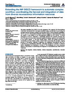
Fig. 7. Overhead on checking for updates
The next experiment measured the cost of generating test cases while modeling database updates. In this experiment we added the update rules to the generation of the DIS and the guards. As each test case is generated, tuples are (logically) inserted and deleted from the AD and SD databases, creating new versions of the database. But, as described in Section 6.1, the guards must be evaluated without changing the state of the database. So each guard performs insertions and deletions by building buffers of inserted and deleted tuples in memory (no insertions or deletions are written to disk). The details of the insertion and deletion buffers are given in Section 5.5.2. The result is shown in Figure 7. We fixed the AD (SD) size at 28000 (16000) tuples (representing the pool of test data). We then performed the same experiment on both systems (no-DB and with updates), summing the individual costs, so a bar in Figure 7 is the sum of the points for the indicated test sequence length in Figure ?? (e.g., the value for test sequence length 25 is the sum over the number of test sequences from 1 to 500). The experiment shows that the cost increase is negligible. The third experiment repeated the second experiment with different database sizes to measure the impact of database size on modeling database updates. The result is shown in Figure ??. The experiment shows that the cost increases linearly with the database size. The final experiment assesses the cost of physically updating the database as it would be during the evaluation of a test case. In this experiment we evaluated the guards, generating a test case, and then simulated the database updates in the evaluation of the test case. For each inserted tuple we “asserted” a new Prolog fact in XSB. The assertion updates the “tabling” of the rule base, changing the state of XSB’s internal database. For each deleted tuple we “retracted” an existing Prolog fact in XSB. We fixed the length of the test sequence at 35 transitions. The result is shown in Figure ??. The experiment demonstrates that database updates are expensive to perform. In the second experiment it took less than six seconds to generate 500 test sequences of 35 transitions each; but in this test, it took almost 22 minutes. Any testing of a web database application would have to perform these updates, using AutoDBT or any other testing system. This experiment demonstrates that the cost of running tests on a web database application far outweighs the cost of generating the test cases and modeling the database updates. 32
9 Case Studies
To better evaluate the cost and utility of AutoDBT, we present several case studies. The case studies examine the characteristics of four web applications, including the number of pages, forms, links, transitions, database-related transitions, and rules in the update specification. We explore each web site, following every link internal to a site and completing every form. Since we do not have access to the application database that supports each site, we model the database interactions based on the input widgets in each form, and estimate the size of the synthetic database. We measure the following aspects of each web site. • Number of logical web pages: A logical web page is a coherent, related group of input widgets or text on a page. The idea is that some physical web pages have several quite distinct regions, each relating to a completely separate function. For instance, it is common for a page to have a navigation pane along the left and/or top border that is unrelated to the content of the page. We count the navigation pane as a separate logical web page. • Number of links: We count internal links. • Number of transitions: We model each transition with a separate data flow specification (an example is given in Table 1 on page 15). • Number of database-related transitions: Only a few of the transitions have interactions with the database, so this can be compared to the number of transitions to get a rough idea of how much of the site is database-related (and how much extra work the designer has to do to model the site). • Number of forms: Some logical web pages are forms that gather data from a user. Forms usually have database-related transitions. • Number of inputs: Most forms consist of several input widgets. Typically, each group of related widgets relate to a tuple in some database relation (i.e. a street address, city, and zip would form a tuple in an address relation). The number of inputs dictates the size of the database-related rules in the input specification. As described in Section 5.3.2 the input specification models how data is input in the application, especially whether it is drawn from the synthetic or application database. There will be at most one database read for each input. If each transition is tested only once, then this is the (maximum) overhead added to the model in terms of database reads. • Min/Max/Med options per input: Many forms have a limited number of potential values, for instance, a widget to collect a person’s “age” allows for at most 120 possible values. We counted the minimum, maximum, and median number of options. The product of the maximum number of options and the number of inputs overestimates the maximum size of the synthetic database (every possible value might be chosen from the synthetic database in a suite of test cases), using the median number gives a truer estimate. • Number of rules in the update specification: As also described in Section 5.3.2 the update specification models expected database updates. The number of database33
related update rules is really just the number of database inserts/deletes/modifications. If each transition is tested only once, then this is the overhead added to the model in terms of database updates.
9.1
Web application 1: WSU’s IT Student Computing Services
WSU’s IT Student Computing Services (SCS) website 9 provides resources and support to students who bring personal computers to campus. The primary services include a list of services rendered, a form for students to sign up for training courses, instructions for connecting a personal computer to the WSU campus network, hours of operation for computer labs and administrative offices, and links to campus computing resources and employment opportunities within SCS. The data collected from this web application is shown in Table 6. The only HTML form in this case study is shown in Figure 8. The rest of the site is comprised of only simple HTML pages and links. The form leads to three database-related transitions: 1) to a successfully added page, 2) to an error page because the input has already been entered to the database, and 3) to an error page that states that insufficient information has been input. There is only one update rule (to add a student to the notification list) and eight inputs, so modeling the database interactions is relatively trivial in this case study.
Measure
Value
Number of Logical Web Pages (N LW P ) Number of Transitions
377
Number of Database-related Transitions Number of Links (N L)
3 169
Number of Forms (N F )
1
Number of Inputs
8
Min/Max/Med Options
5/30/17.5
Number of Update Rules
1
Table 6 Characteristics of web application 1
9
65
http://www.scs.wsu.edu
34
Fig. 8. SCS Training Sign-Up Form
9.2
Web application 2: WSU’s eInfoCenter for Current Students
WSU’s eInfoCenter for current students 10 provides central access for online resources available to the general student population. The primary resources provided by the site include access to view and/or change undergraduate student academic planning materials, academic records, university account records, student contact information, financial aid records and library records. The site also provides the mechanism to register for classes and to check registration information (for example, times and current holds). The data characteristics of this web application are in Table 7. There are 37 forms in this application. Most of the forms collect input to read information from the AD. Only five forms update the database, including that that allow students to register for classes and update contact information.
9.3
Web application 3: WSU’s ResNet Self-Certification Web Page
WSU’s ResNet Self-Certification Web Page 11 provides are the ability to download WSU site licensed anti-virus software and to register Internet capable devices with the WSU DHCP servers. The characteristics of this web application are shown in 10 11
http://www.it.wsu.edu/AIS/SIC/cgi-bin/info ctr.cgi?site=SIC https://www.wsu.edu/ naliv/index.cgi
35
Measure
Value
Number of Logical Web Pages (N LW P )
88
Number of Transitions
530
Number of Database-related Transitions
122
Number of Links (N L)
218
Number of Forms (N F )
37
Number of Inputs
133
Min/Max/Med Inputs per Form Min/Max/Med Options
1/18/2 2/116/7.5
Number of Update Rules
5
Table 7 Characteristics of web application 2
Table 8.
Measure
Value
Number of Logical Web Pages (N LW P )
14
Number of Transitions
42
Number of Database-Related Transitions
36
Number of Links (N L)
31
Number of Forms (N F )
11
Number of Inputs
28
Min/Max/Med Inputs per Form Min/Max/Med Options
1/5/1 2/15/11
Number of Update Rules Table 8 Measures Calculated for Case Study 4
3
In this application, forms collect input from the user to authorize users to download data. Database reads vastly outnumber database updates; the few updates are for registering devices with DHCP servers. 36
9.4
Web application 4: Mapquest
Mapquest 12 provides an example of a small, but highly connected web application. The primary resources on the site are the ability to get the address of a business or airport including a map of the surrounding area, a map of the area surrounding a given address, and driving directions between any two addresses. The data characteristics of this web application are in Table 9. Measure
Value
Number of Logical Web Pages (N LW P )
81
Number of Transitions
832
Number of Database-Related Transitions
750
Number of Links (N L)
441
Number of Forms (N F )
30
Number of Inputs
147
Min/Max/Med Inputs per Form Min/Max/Med Options
1/16/4 2/233/2
Number of Update Rules
0
Table 9 Characteristics of web application 3
Though Mapquest has many forms and database-related transitions, the application performs only database reads and has no database updates (updates are carried out behind the public interface). The synthetic database is a small fraction of the size of the application database since the latter contains maps and map-related data for the entire world, while the former contains values unrelated to geographic locations (i.e. bad zipcodes, wrong city names, misspelled states, etc.).
9.5
Summary of the characteristics of four web applications
The case studies show that web database applications sometimes have a large percentage of database-related transitions (the percentage in case study 3 is 85%), some have many forms (40% of case study 4 consists of forms). Some forms have many input widgets and options. Overall, however, most of the transitions involve only database reads; each of the case studies had very few database updates. Although database updates are rare, it is critically important to be able to model and test them. AutoDBT requires that a test designer create an update specification to 12
http://www.mapquest.com
37
describe the number of database updates. If there are generally few updates, the update specification will be small. When modeling a web site, care must be taken to specify whether input is taken from the application database or the synthetic database. In the case studies, some of the application databases are quite large (especially for Mapquest, on the order of gigabytes to terabytes of mapping data). But in the case studies, the synthetic databases are all very small (on the order of a kilobytes). Small synthetic databases may be the norm for testing web database applications since the synthetic database only needs to contain data not present in the application database. In summary, we believe that most web database applications will be similar to the case studies. The overhead on modeling and testing database activity, in terms of additional work for test design and execution is relatively small but critically important.
10
Conclusions and Future Work
Many organizations conduct a substantial part of their business through web applications. These web applications may change over time as developers fix bugs or add new functionality. An initial version of a web application may have a clean database, whereas subsequent versions of the application may use a database that is populated from a previously running version. Test cases may depend on certain data being available or absent in the application database. Current testing techniques do not thoroughly address issues in testing database updates. AutoDBT is a comprehensive testing framework that extends a model-based approach to testing to also examine database updates. To use AutoDBT, a modeler develops a model of the application. The model consists of a state transition diagram that shows how users navigate from page to page in the application and a data specification that describes how data is input and the database is updated. Once the model is complete, a tester decides on test coverage criteria. AutoDBT uses the model and the coverage criteria to generate test cases. Each test case is self-contained. AutoDBT selects test case data from either the application database or the synthesized database as necessary. AutoDBT also generates a guard for each test. The guard checks whether the current state of the database is conducive to generating a test case since previous tests may modify the database to an extent that renders the test case generation impossible. Finally, AutoDBT also generates an oracle for each test. The oracle checks whether a test case correctly updates the application database. The main contributions of this paper include a design of AutoDBT, a description of a prototype implementation, and case studies that show that the additional overhead of modeling the interactions of the application with the database is modest. Future 38
work includes modifying AutoDBT for performance testing. Another vein of future work is to improve the feedback on failed tests. A test fails because an oracle detects a problem in the application database. Ideally the oracle would also provide a hint on how to fix the problem. We’d also like to improve the guards. A guard checks whether a test case can be attempted, but it would be better if the guard populated the database with the data that is needed to perform the test.
References
[1] A. A. Andrews, J. Offutt, R. T. Alexander. Testing Web Applications By Modeling with FSMs. Software Systems and Modeling, 4(3):326–345, July 2005. [2] N. Alshahwan and M. Harman. Automated Session Data Repair for Web Application Regression Testing. In Proceedings of the International Conference on Software Testing, Verification and Validation, 2002. [3] B. Beizer. Black-Box Testing. Wiley, 1995. [4] E. Beltrami. Models for Public Systems Analysis, 1977. [5] L. Bodin, A. Tucker. Model for Municipal Street Sweeping Operations. In Modules in Applied Mathematics Vol. 3: Discrete and System Models, 1983. [6] M. Benedikt, J. Freire, P. Godefroid. VeriWeb: Automatically Testing Dynamic Web Sites. In Proceedings International WWW Conference(11), Honolulu, Hawaii, USA. 2002 [7] D. Chays, S. Dan, P. G. Frankl, F. I. Vokolos, E. J. Weyuker. A Framework for Testing Database Applications. In Proc. of the International Symposium on Software Testing and Analysis, pp. 147–157, 2000. [8] T. S. Chow. Testing Software Design Modeled by Finite-State Machines. In IEEE Transactions on Software Engineering, SE-4(3), pp. 178–187, May 1978. [9] Y. Deng, P. Frankl, J. Wang. Testing web database applications. In Workshop on testing, analysis and verification of web services (TAV-WEB), pp. 1-10, September 2004. [10] G. Di Lucca, A. Fasolino F. Faralli. Testing Web Applications. In International Conference on Software Maintenance, pp. 310–319, October 2002. [11] S. Elbaum, G. Rothermel, S. Karre, M. Fisher. Leveraging user session data to support web application testing. In IEEE Transactions on Software Engineering, 31(3):187202, March 2005. [12] R. Elmasri, S. B. Navathe. Fundamentals of Database Systems. Third Edition. Addison-Wesley 2000.
39
[13] S. Fujiwara, G. Bochmann, F. Khendek, M. Amalou, and A. Ghedasmi. Test selection based on finite state models. IEEE Transactions on Software Engineering, 17(6):591– 603, June 1991. [14] J. Gray, P. Sundaresan, S. Englert, K. Baclawski, P.J. Weinberger. Quickly Generating Billion Record Synthetic Databases. In Proc. ACM SIGMOD, pp. 243-252, 1994 [15] W. Halfond, A. Orso. Improving test case generation for web applications using automated interface discovery. In ESEC / 15. SIGSOFT FSE, pp. 145–154, September 2007. [16] R. Hower. Web site test tools and site management tools. Software QA and Testing Resource Center, 2002. www.softwareqatest.com/qatweb1.html (accessed November 2003). [17] C.L. Hsu, H.C. Liao, J.L. Chen, and F.J.Wang. A web database application model for software maintenance. In 4th International Symposium on Autonomous Decentralized Systems, pp. 338–344, March 1999. [18] X. Jia, H. Liu. Rigorous and Automatic Testing of Web Application. In Proceedings of the 6th IASTED International Conference on Software Engineering and Applications (SEA 2002), Cambridge, MA, USA. pp. 280–285, November 2002 [19] D. Kung, C. H. Liu, and P. Hsia. A model-based approach for testing Web applications. In Proc. of Twelfth International Conference on Software Engineering and Knowledge Engineering, Chicago, IL, July 2000. [20] D. Kung, C. H. Liu, and P. Hsia. An object-oriented Web test model for testing Web applications. In Proc. of IEEE 24th Annual International Computer Software and Applications Conference (COMP-SAC2000), pp. 537–542, Taipei, Taiwan, October 2000. [21] D. Lee and M. Yannakakis, Principles and Methods of Testing Finite State Machines, a survey. In Proceedings of the IEEE, (84)8:1090-1123, 1996. [22] G. M. Kapfhammer and M. Soffa. A family of test adequacy criteria for databasedriven applications. In Proceedings of ESEC / SIGSOFT FSE, pp. 98–107, 2003. [23] S. C. Lee and J. Offutt. Generating test cases for XML-based Web component interactions using mutation analysis. In Proceedings of the 12th International Symposium on Software Reliability Engineering, pp. 200–209, Hong Kong China, November 2001. [24] C.H. Liu, D. Kung, P. Hsia, and C.T. Hsu. Structural testing of web applications,. In 11th International Symposium on Software Reliability Engineering, pp. 84–96, October 2000. [25] N. Nyman. GUI Application Testing with Dumb Monkeys. In Proceedings of STAR West, 1998. [26] J. Offutt and A. Abdurazik. Generating tests from UML specifications. In Proceedings of the Second IEEE International Conference on the Unified Modeling Language (UML99), Lecture Notes in Computer Science Volume 1723. pp. 416–429, Fort Collins, CO, October 1999.
40
[27] J. Ofutt, S. Liu, A. Abdurazik, and P. Ammann. Generating test data from state-based specifications. The Journal of Software Testing, Verification, and Reliability, 12(1):25– 53, March 2003. [28] J. Offutt, Y. Wu, X. Du, H. Huang. Bypass Testing of Web Applications. In 15th International Symposium on Software Reliability Engineering, pp. 187-197, November 2004. [29] L. Ran, C. Dyreson, A. Andrews. AutoDBT: A Framework for Automatic Testing of Web Database Applications. In International Conference on Web Information Systems Engineering (WISE), LNCS 3306, pp. 181–192, November 2004. [30] F. Ricca, P. Tonella. Analysis and Testing of Web Applications. In 23rd International Conference on Software Engineering (ICSE), Toronto, Ontario, Canada. pp. 25–34, May 2001. [31] S. Sampath, R. Bryce, G. Viswanath, V, Kandimalla, A. Koru. Prioritizing Usersession-based Test Cases for Web Application Testing. In the International Conference on Software Testing, Verification and Validation, pp.X-Y, April 2008. [32] S. Sampath, S. Sprenkle, E. Gibson, L. Pollock, A. Souter. Applying Concept Analysis to User-session-based Testing of Web Applications. In IEEE Transactions on Software Engineering, 33(10):643–658, October 2007. [33] S. Sprenkle, L. Pollock, H. Esquivel, B. Hazelwood, and S. Ecott. Automated Oracle Comparators for Testing Web Applications. In 18th IEEE International Symposium on Software Reliability Engineering, pp. 117–126, November 2007. [34] S. Sprenkle, S. Sampath, E. Gibson, A. Souter, L. Pollock. An Empirical Comparison of Test Suite Reduction Techniques for User-session-based Testing of Web Applications. In International Conference on Software Maintenance, pp. 587– 596, September 2005. [35] D. Slutz. Massive stochastic testing of SQL, In Proceedings of the Twenty-Fourth International Conference on Very-Large Databases, Morgan Kaufmann, pp. 618–622, 1998. [36] Transaction Processing Performance Council. TPC-Benchmark C. 1998. [37] J. Whittaker, M. Thomason. A Markov Chain Model for Statistical Software Testing. In IEEE Transactions on Software Engineering, 20(10):812-824, 1992. [38] David Willmor and Suzanne M. Embury. An intensional approach to the specification of test cases for database applications. In Proceeding of ICSE, 2006, Shanghai, China pp. 102–111. [39] J. Yang, J. Huang, F. Wang, and W. Chu. An object-oriented architecture supporting Web application testing. In First Asian-Pacific Conference on Quality Software (APAQS ’99), pp. 122–129, Japan, December 1999. [40] J. Yang, J. Huang, F. Wang, and W. Chu. Constructing an object-oriented architecture for Web application testing. Journal of Information Science and Engineering, 18(1):59–84, January 2002.
41
A An example
As an example, consider transitions 4, 10, and 6 in the OCRS FSM. Transition 4 This transition does not perform an update. The input specification is listed below. input4 (Fn, Ln, C#) :AD Customer(Fn, Ln, Cid), AD Reserves(Cid, C#) The corresponding dynamic input specification follows. input4 (Fn, Ln, C#, AULin , AULout ) :AD Customer(Fn, Ln, Cid, AULin ), AD Reserves(Cid, C#, AULin ), AULin = AULout Transition 10 This transition makes an update that depends on the current input. Its input specification is listed below. input10 (C#) :- AD Reservation(C#, , , ) The update specification for this transition follows. delete AD Reservation(C#, Pd, Rd, Ct) :input10 (C#), AD Reservation(C#, Pd, Rd, Ct) delete AD Reserves(Cid, C#) :input10 (C#), AD Reserves(Cid, C#) The current input (input10 (C#)) in the body of the update specification is ignored in the body of dynamic input specification. The corresponding dynamic input specification follows. input10 (C#, AULin , AULout ) :AD Reservation(C#, , , , AULin ), AD Reservation(C#, Pd, Rd, Ct, AULin ), AD Reserves(Cid, C#, AULin ), delete AD(Reservation(C#, Pd, Rd, Ct), AULin , AULout’ ), delete AD(Reserves(Cid, C#), AULout’ , AULout ) 42
Since there is more than one AD version predicate, the version produced by the first predicate (AULout’ ) is input into the second one. Transition 6 This transition makes an update that depends on the previous input. Its input specification is listed below. input6 (Pd, Rd, Ct) :SD Reservation( , Pd, Rd, Ct). The update specification for this transition follows. delete AD Reservation(C#, Pd, Rd, Ct) :input4 ( , , C#), AD Reservation(C#, Pd, Rd, Ct) insert AD Reservation(C#, Pd, Rd, Ct) :input4 ( , , C#), input6 (Pd, Rd, Ct) (The current input (input6 (Pd, Rd, Ct)) involved in the body of the update specification will be ignored from the body of dynamic input specification.) The corresponding dynamic input specification: input6 (Pd, Rd, Ct, C#, AULin , AULout , SULin , SULout ) :SD Reservation( , Pd, Rd, Ct, SULin ), AD Reservation(C#, Pd’, Rd’, Ct’, AULin ), delete AD(Reservation(C#, Pd’, Rd’, Ct’), AULin , AULt ), insert AD(Reservation(C#, Pd, Rd, Ct), AULt , AULout ), delete SD(Reservation( , Pd, Rd, Ct), SULin , SULout ).
43