therefore. the quality of products can be improved at a low cost (Duncan. ...... Wesley. Kiselev. S. B. 1998. Cubic crossover equation of state. Fluid P/IU.
O
KNOWLEDGE BASE SPECIFICATION TO AUTOMATE THE FLUID CRITICAL POINT OF FLUIDS JOSEFINA BAR R ERA - CO R TE S CINVESTAV, Department of Biotechnology and Bioengineering, Cot. San Pedro Zacatenco. Mexico. D.F. C.P.
JEAN PIERRE ASTRUC and ROLAND TUFEU Laboratoire d'lngenierie des Materiaux et des Hautes Pressions, CNRS-Universite Paris-Nord, lnsitut Galilee. Villetaneuse, France hntou;c*
ANA M A R ~ AMART~NEZ-ENRIQUEZ CINVESTAV, Department of Electrical Engineering, Col. San Pedro Zacotenco, Mexico, D.F. C.P.
The flexible acquisition and processing of information by means of expert systems (ES) is a very attrxti\.e idea which has contributed to changing the control of process scope (Crowe & Vassiliadis. 1995; Stephanopoulos & Han. 1996). An ES may be used as a tool for the automatization of a complex Theauthors tvish to Dr. Arturo hiorales Acevedo tor his thorough reading. insightful comments. and suggested improvements. This research n a s initially developed into the collaboration Mexico-France through CONACYT (scholarship 18860) . ~ n dnow it has been pursued ;I[ the CINVESTAV. Address correspondence to Josetina Barrera-Cortes. CINVESTAV. Department of Biotechnology and Bioengineering. .Av. lnst~tutoPol~ti'n~coNac~onal2508. Col. San Pedro Zacatenco. Mexico. D.F. C.P. 07300. E-ma~l:lharreri~~rr nla~l.~in~cstav.mx
0
process in industry because an exact mathematical model is not required. and therefore. the quality of products can be improved at a low cost (Duncan. 1989: Norman & Naveed. 1988: Vranei. StanojeviC. & Subaiic. 1994). T h e first applications of ES L O industrial systems failed because the knowledge and control structures were not explici~lyseparated. making it difficult to define appropriately or to modif! them (Hayes-Roth. Waterman. & Lenat. 1983: Motoda. 1994). During [he last decade. new research areas were created in order to solve these kinds of problems and now new representation models and me~hodologiesare available to acquire, organize. verify, and validate the knowledge itself to be provided to ES (Birky & McAvoy. 1990; Benjamins. 1995: Studer. Benjamins. & Fensel. 1998). In this article a detailed description of a n anal~ticalprocedure is presented for specifying the knowledge base required by an ES applied to determine the critical point of pure fluids and mixtures at Ion concentrations. The importance of the analytical approach implemented here is to describe a method for systematically acquiring and organizing the knowledge required in the supervision and control of a laboratory process. according to the requirements and characteristics of this in real time. The critical point (liquid-vapor) of a fluid represents the maximal pressure a n d temperature conditions where the liquid and \.apor phases are coexisting in equilibrium (Williams, 1981; Richon. 1995). This equilibrium point is important because the extraction of natural compounds. near this point for the solvent ( C 0 2 is commonly used). reduces the operational costs a n d increases extraction process efficiency (Tufeu. Subra. & Plateaux, 1993). Currently, the critical point determination is made manually, taking around 1 week of measurements (Tufeu et al., 1993). To improve the process and measuring time. the utilization of ES techniques is proposed because there is concern with an uncertain problem (instability near the critical point) where the experimental procedure and criteria of an expert are determining factors (Perrut. 1995). In recent years. methods focused to automate the experimental critical point determination have been developed. One of these. for example, is based o n measuring the speed of sound in the fluid itself and correlatinz this to thermodynamical properties of the fluid (Kordiko\vski & Poliakoff. 1998). Another method is based on measuring the vibration frequency of a container filled with the fluid under study, and correlating it again t o the critical point parameters (Bouchot & Richon. 1998). One problem with these methods is that they cannot be applied to different fluids because the critical point temperature may vary greatly from one fluid to another: for example. it is 273°K for the ethylene and 644°K for the water: the critical pressure is of 49.074 x 10' and 2 13.7 x lo5 Pa. respectively.
.
'
455
H?.hrid lntelligerit Control of u Laboratory Experience
For automating the experimental procedure in this work, the selected techniques are an expert system (ES) and an analysis image algorithm (AIA) based on neural networks (NN). The ES was assigned to carry out tasks related to supervision and control of the process, and the AIA to measure one experimental variable of visual type. the liquid/vapor volume ratio of the fluid phases (Lee, Mohankrishnan, & Paulik, 1998). For the ES we used an expert system generator (ESG) called CHRONOS TM and for the AIA. a feedforward neural network (FFNN), which was trained using the backpropagation gradient algorithm (Astruc & Barrera-Cortb, 1993). This paper proceeds as follows: in the second section the set-up for the experimental procedure is described; the third section outlines an analytical procedure focused on solving problems of supervision and control of chemical process; the fourth section elucidates the knowledge-based specification applied to the critical point determination process; the fifth section explains the expert system implementation using the expert system shell CHRONOS TM; the sixth section analyzes verification and validation of the expert system constructed, which was carried out determining the critical point of the pure fluids---C02-NO2, and SFS, and mixtures of limoneneCO: at a low concentration (0-0.0004 wlw).
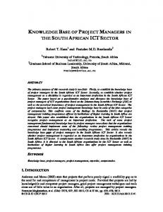
EXPERIMENTAL PROCEDURE The experimental determination of the critical point of pure fluids and mixtures of low concentration consists in varying pressure (P), volume (V), and temperature (T) until the density of the liquid and vapor fluid phases become the same. This condition is identified by observing when the liquidvapor interface (meniscus, mp) disappears at the middle of the experimental cell (Vli, = V,,,), under a small pressure increase, or inversely, when the meniscus reappears under a small pressure decrease, also at the middle of the experimental cell. The experimental setup used is composed of (Figure 1):
-
1. A sapphire cell, where the fluid to be analyzed is placed: 2. A double-walled air thermostat which keeps the cell at a constant temperature; 3. a PID temperature controller to fix the fluid temperature; 4. a mechanical piston connected to the bottom of the cell. which allows the volume ratio of the fluid phases through an oil-mercury piston to shift: 5. a pressure transducer, resistive joint, for measuring the fluid pressure; 6. two platinum probes, to measure indirectly the fluid temperature, 7. an agitation mechanism, to homogenize the fluid temperature; 8. a mercury container, to protect the piston against damage provoked by the mercury entrance.
H j d ~ i dIrtrelligcnt Control of a Lahoratorj' Esperic.rlce
457
(Davis. 1983: Sage. 1989). he task-oriented approach was selected because i t can be used at any level of abstraction to define system objectives and actions to be performed on the system itself (Chandrasekaran. Todd. & Smith, 1992). In the design of structured systems, the application of the lifecycle of systems design is very common due to the easy data management in a sequential way for computing purposes. In this work the lifecycle of systems design has been used because it is a more complete design methodology than the problemsolving methods commonly used for implementing ES (Belljamins, 1995: Chan. Tontiwachwuthikul, & Cercone, 1995). The analytical approach proceeds as follows. S ~ L I ~I. LIdentification J of the problem. One of the main purposes in control process is to know the evolution process of the fluid states. Therefore, the problem identification involves a description of the desired initial and final states of the fluid, in order to facilitate the visualization of change direction of each process variable. Stage 2. Conceptualization of the process solution. Fundamental knowledge of the fluid treatment is introduced in this phase. This is described as a sequence of tasks showing the desired evolution of fluid state. The task sequence is related to unitary operations involved in the experimental procedure in question. Stage 3. Conception of the process solution. The technological aspects of the process performance are inzerted here. They involve the experimental methods concerning the measurement and/or control of each variable. As in the previous phase. this description is made in terms of the tasks to be achieved by the ES. Stage 4. Implementation. In this phase the operational procedure of the experimental setup is introduced. The procedure must be described in terms of the tasks to be carried out with the experimental equipment and through the instrumentation. Stage 5. Organization of the knowledge. As is known, a production rule is executed as soon as the rule antecedents are validated. In order to combine this operation way of the ES with the task sequence requirements of the experimental procedure. the organization of tasks in a hierarchical structure is proposed. The advantages of this structure are: (1) sequence of tasks, (2) identification of the tasks repeated. so that during the implementation process they can be organized in a single module. and (3) facilitation of the abstraction of the system characteristics to be implemented. In this case. for example, the control system requires one to temporize and place the tasks to be performed in a sequential procedure. processing the information in real time and achieving the tasks in a parallel way
(multitasking). This analytical procedure can be recursively applied in each step of itself.
SPECIFICATION OF THE KNOWLEDGE REQUIRED BY THE CONTROL SYSTE,M This section describes how to identify the problem as well as how to acquire and organize the knowledge required by the ES, applying the lifecycle of system design. It includes the phases: problem statement and analysis of tasks for !he critical point determination.
Problem Statement T o state the problem the lifecycle of system design was applied involving: identification of the problem, proposition of solution alternatives, and definition of the general tasks to be carried out by the control system.
Idmtijication of the prohlem For a good automatic control of the critical point determination, it is necessary to have:
1 . a deep knowledge of fluid behavior near the critical point, which allows one to establish the duration of task performance; 2. a precise description of the experimental procedure, that allows one to determine the tasks related to the critical point determination, such as increase of temperature, equalization of fluid densities, and volume measurement of the liquid-vapor phases of the fluid; 3. a complete description of the experimental setup operation, for determining the way for performing the tasks. For instance. the equalization of fluid densities requires shifting the piston, measuring the meniscus position, and opening/closing of valves, principally. The whole set of tasks is organized in a logical sequence. according to the requirements of the experimental process, in order to be carried out in real time. It is important to mention that the automatization of the critical point experiment requires specific models relating the experimental equipment operation with the state evolution of the fluid. As these kind of models are not available to reproduce the fluid behavior near the critical point. the ES approach is the best option to automate this experiment.
(=I
Information
I=
Exp::nta'
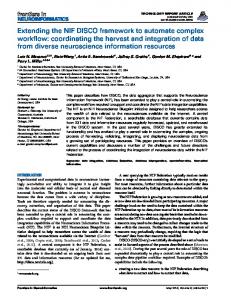
A1tmratil.e So111tiotr.s As described in the second section. \.ariables to be controlled are temperature. pressure. and \.olume. Temper:lture :lnd pressure are registered by standard methods. In the case of \ . o l ~ ~ m since e. visual measurements are involved. an algorithm of image analysis based on neural networks was developed (Astruc. & Barrera-CortPs. 1993). The implementation of this algorithm requires a charge couple device ( C C D camera), for translating the visual into digital information and a shaker system. in order to take a clear image of the liquid-vapor interfilce of the fluid. The fluid volume control involves the opening and closing of check i d v e s . so the manual valves originally installed in the equipment were changed by electro-pneumatical ones. In order to make the operation ot'the experimental setup easier. a control system made of two modules was sonstructed: one for manipulating the functions associated with process command (process conmlard), and the other, for placing functions associated with data manipulation (irlfbrmarion transport) (Figure 2). The purpose of this structure is to facilitate system maintenance and portability of the experimental procedure to other frameworks. Thus. if a change is executed in the experimental procedure, the only module affected would be the process command one. On the other hand, if a control instrument is out of order. its replacement would only affect the inj~~rrwitiorz transport module. Dcfitiitiotr of Tasks The automatic control must be performed under safe conditions and in such a way that it assures communication between the control system and the experimental setup. In order to satisfy these two requirements. besides the principal task-cieterr?iirintior~ of rhc c.riticd poirzt-two other specialized tasks were designed and included in order to be performed by the same control system (Figure 3). These tasks are as follows. Surwiiimcc of espc.rimvztai sc.tup .sc~fi)tj..The focus of this task is to test the functional state of instruments. diagnose instrument malfunctions. and repair some electrical failures. T o nc11iei.e this task. a deductive method was applied: it consists of failure diagnosis through identification of symptoms. The knondedge required to perform this task was acquired from a study of
Regulation of '"put OUtPUt Information
-
i
I
Surveillance of the experimental setup safety
, / / j
information transport
/
I ,Experimental
+
setup
131
i (A i
FIGURE 3. Specialized tasks to be achieved h! ~ h control e system
the experimental setup malfunctions. as well as from a study of the failures detected during the construction of the control system.
Regrllation of itzput-outpzrt it~fimintiot~. The ES language is commonly based o n production rules (if (antecedents) then (actions) end if), which are executed as soon as the rule antecedents are validated. This execution of rules is one of the principal problems for performing sequential sets of instructions. Hence, to overcome this problem, a data manipulation strategy based on the test of input-output data. between the ES and the experimental set up and the definition of priority to the rules. was implemented.
Analysis of Tasks In this phase of the lifecycle of system design. the [asks identified in the previous section (determination of the critical point. sur~eillanceof experimental setup safety, and regulation of input-output information) must be analyzed following the approach described in the third section. T o illustrate this procedure only the task related to the critical point determination was analyzed.
Stage I. Idenrificuriotr of rhe Initial arid Final Stares of rlre FlrriJ A direct and quick determination of the critical point requires precise knowledge of the initial state of the fuid. which allows one to mticipate the direction of change of each variable in\folved in [he esperimenlal procedure. In fluid thermodynamics. the only state well known and easily identified is the
Initial state T, V and P biphasic fluid
Final state determination of the critical point Supercritical fluid
V and P : temperature, volume and pressure of the fluid, at a current time Tc, Vc and PC: temperature, volume and pressure of the fluid, at the critical point
biphasical state. Thus. the critical point cfetennination starts from a known biphasical state (room temperature (30 C ) . pressure of 60 x 10' Pa. and Vl;, = V,,,). The final state is the critical point \\here these two phases giire rise to a single liquid-vapor phase ( s u p e ~ ~ ~ i t istate). c a l Representation of the initial m d final states is shown i n Fis~ir-e4. Stage 2. C11ar1gc.sof Procc.ss I'ariahl~~.~ To r1wrc1.st hr Criticcrl Poirrt of the Fluid Fluid evolution from the bip11asic:ll to the supercritical state is performed by the variation of temperature. pressure. and ~ v l u m e For . control purposes. the temperature is taken :is the ~xriableto be controlled. since it greatly affects the current state of the fl u h . Volume of each phase of the fluid was maintained constant (Vli,/V2,, = 1 ) in order to satisfy the criterion of the critical point determination. related to density eq~~alization of fluid phases (DENSITYliqUid = DENSITY,:,,). Finally. the pressure was defined as the variable to be monitored due to its strong relation to the other variables (temperature and volume). According to the above paragr~lph.the tasks to be carried out by the ES are the following (Figure 5 ) : ( 1 ) ~~e~rrrrlir,rrio~z of'rhc ~~)llrtlic~ o j ' r l i ~liqlritl-wpor ~ p1rcr.sr.s. (2) t~rrns~rrc~tnc~tir oj'tlzc l.ol~rtt~c rrlrio and/or ~lzc~rr.~~r~.c~ttic~t~t of rhc tmrisurs pnsirioti sc~par.trtitrgrlic tu*o,fl~rirl pl~r~.sc~s: xnd ( 3 ) itzcr.c~r.rcof' rcwprrrrtlrrcJ. The knowledge required to perform these tasks (temperature increase. time of stabilization of temperature. and the tinic elapsed for the piston shift) is included in step four. T o achieve the tasks defined in this stage. measurement and control methods are applied. The introduction of these methods is explined in the next stage. Stage 3. Se qrreme of Tcr.sk.s ill Ortlcr to Cotrtrol thc Expcrirrr~rrtalVariah1e.s Tltc crpc~lirtrtiottoj'rltc~I ~ L I I I 01'1hc I ~ liqllicl i.rrpor. pitcr.sc~.sof'~lic,Hlrirl.The displacement of the current meniscus position towards the meniscus position
Q Initial state
1
Equalization of the volume of the fluid phases
A
I
-
P, V, T and mp
I
P,V, T and mp
Increase of temperature
Measurement of the meniscus position
I
mp: position of the meniscus (% of Vle total volume of the fluid1
I
PC, Vc, T c
Final state FIGURE 5. Variulions of process varioblrs towards the cri~iccllpoint 01' thc Iluid.
desired (Vliquid= Vgas)could be carried out with a single displacement. if the mathematical model relating piston disp1ac;emeiit to the meniscus position were known. Since this mathematical inodel is not available (Kiselev, Rainwater, & Huber, 1998; Kiselev. 1998; Stockfleth. & Dohrn. 1998), the meniscus displacement and the measurement of its position are carried out gradually until the volume phases of the fluid are equalized (Vliquid = Vgas), as it is shown in Figure 6. The /neastrreme/zt of the n~e/zisc.m positiorz. It is composed of two sequential subtasks: ( 1 ) homogenization of fluid temperature. with the purpose of clarifying the liquid-vapor interface. which usually becomes blurry as a result o f the temperature gradient established along the fluid column: and (2) measurement of the meniscus position. in charge of taking the image of the fluid and calculating the meniscus position by applying an algorithm based on neural networks (Figure 6). 1nc.i-easeof teinpcr.crtlrr-c..Determine the increments of temperature from the previous analysis of the evolution of the fluid state and survey the nonexecution of other tasks until the fluid temperature is uniform. The analysis of tasks for the measurement and control of the experimental variables is carried out until the tasks are directly related to the instrument operation.
FICCRE 6. Tasks involved in the changes of the experimental variables. mp: meniscus position.
Sta