condition monitoring and both diagnostics and prognostics. This paper proposes two solutions for detecting degradation in electrodes that interface to fluidic or ...
2009 European Test Symposium
Built-in Test Solutions for the Electrode Structures in Bio-Fluidic Microsystems 1
Q Al-Gayem1, H Liu2, A Richardson1 & N Burd1.
Centre for Microsystems Engineering, Lancaster University, Lancaster, UK; 2 Moor Instruments Ltd, Axminster, UK. {q.al-gayem,a.richardson,n.burd}@Lancaster.ac.uk In the field of Microsystems, embedded test is now acknowledged to be a crucial constraint within the design space of MEMS-based solutions [4]. Within this work, testability has been shown to be especially important within the design flow for microfluidic systems and their biological applications due to the immaturity of the field and limited understanding of the sources of failure. There has also been work on the testing process for the interconnect infrastructure of microfluidic chips [5]. Here mechanical and fluidic testing apparatus and protocols for characterizing both chip-to-chip and world-to-chip interconnects have been proposed. Standardized figures of merit have been presented and developed to compare interconnect structures and techniques. Reliability issues for multiple interconnects between chips have also been addressed. Oscillation-Based Test (OBT) has been evaluated within MEMS based systems through work on a monolithic magnetometer [6]. The natural frequency of the cantilever has been chosen to be the main input parameter to the test strategy. The tolerance band and detection range in the case of small deviations applied to technological process parameters have been assessed. The potential for using OBT in a DNA sensor array has also been discussed in [7] and [8] where the modes of sensing and test can both be realised in an oscillator-based structure. The idea of monitoring power supply current (IDDQ) has been applied to an electro-fluidic interface in a FlowFET system [9] where the system under test is fundamentally electronic but applied within a microfluidic environment. Bridging faults within this FlowFET system have been shown to be efficiently detected using this method. A functional test for a continuous FlowFET has also been demonstrated in [9]. The underlying principle is that typical faults, such as degraded gate voltages, jammed particles in the channel or leakage will influence the fluid velocity and the duration of fluid charging. The device therefore makes use of reservoirs where the occurrence of faults will lead to either reduced volume of fluid in the reservoirs, or longer durations to fill the reservoirs. For discrete droplet-based microfluidic systems, both catastrophic and parametric faults have been detected by electro-statically controlling and tracking the motion of test droplets [10]. The detection of these test droplets is through a simple RC oscillator formed by a pair of driving electrodes and the fluid between them as the dielectric. The presence of droplets is sensed through the change in the capacitance of this structure due to the fact that the filling medium and the droplet have different permittivity.
Abstract— Electrodes are fundamental to the reliable operation of a new generation of portable bio-analytical instruments based around microsystems technology. The importance of eliminating false positives and false negatives for these instruments is driving work around embedded test, condition monitoring and both diagnostics and prognostics. This paper proposes two solutions for detecting degradation in electrodes that interface to fluidic or biological systems and form the basis of numerous actuation and sensing mechanisms in the bio-fluidics area. A low frequency, impedance based method for identifying degraded structures within an array is proposed that is backed up by physical measurements from an electrode array for drug testing on cardiac and neuron tissue. In addition, a mid-frequency oscillation test is proposed which is based on the sensitivity of the bio-fluidic interface capacitance to degradation, contamination and fouling.
I. INTRODUCTION AND STATE-OF-THE-ART IN EMBEDDED TEST STRATEGIES FOR BIO-FLUIDIC MICROSYSTEMS Microfluidics is an emerging field that has the potential to stimulate the integration of silicon based sensors and electronics within portable bio-fluidic instruments. The market sectors of specific interest include medical diagnostics, industrial control, environmental monitoring and pharmacology. Examples are DNA extraction from blood, detection of pathogens, e.g. GMO’s or allergens, replacement of animal testing, etc. In most cases the value of this work is derived from the ability to generate enhanced measurements from extremely small samples (few ml) at low cost. The use of microfluidics in molecular biology has already been shown to offer benefits such as improved sensitivity and speed of analysis. An example here is a charge based capacitive biosensor for bacteria growth monitoring (BGM) presented by [1]. The sensor chip is implemented through a CMOS process in order to show the applicability of the proposed on-chip capacitive technique for BGM purposes. The verification of this capacitive method was through the use of diluted E Coli bacteria in an LB solution. In general, although there are a number of extremely interesting technologies capable of integrating microfluidics with electronic control and processing [2], few if any commercial implementations exist. Accelerating the uptake of these technologies is hence a core mission of numerous public bodies. Solutions for defining efficient non-destructive production test strategies, fault tolerant design features and integrated health monitoring are expected to be important contributions towards this goal [3]. 1530-1877/09 $25.00 © 2009 IEEE DOI 10.1109/ETS.2009.24
73
Authorized licensed use limited to: Lancaster University Library. Downloaded on November 25, 2009 at 07:25 from IEEE Xplore. Restrictions apply.
impedance of the porous surface, RS the electrolyte spreading resistance and CX is the parasitic capacitance.
Furthermore, based on the test results, the 2-D EWOD (electro-wetting on dielectric) arrays with open structure can be reconfigured in order to reallocate resources and avoid using the sites marked faulty. In [11] a droplet routing technique on a digital microfluidic device is proposed to ensure fault-tolerant behavior. Three typical faults are built into fault models for this device. This method gave efficient solutions to problems like optimal routing, run-time fault diagnosis, and subsequent fault recovery. The authors also suggested locations for check-cells to minimize the number of droplet presence sensors required to be integrated in the device. The dependability has also improved by using digital microfluidic logic gates. In [12] a fault diagnosis method to locate a single defective cell and multiple rows/columns with defective cells in a digital microfluidic array has been presented. This method utilizes digital microfluidic exclusive-or gates to implement an output comparitor. It also suggests using photo diode detectors instead of capacitive-sensing circuits to avoid the complicated pulse-sequence analysis. This work complements the international effort to advance the field of embedded test for microfluidic systems and builds on initial work on both an MEA (micro-electrode array) structure and full bio-diagnostic system presented in [13]. II.
A SELF TEST SOLUTION :
C EDL R CT CX
ZW
RS
ZP
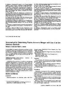
Figure 1 Circuit model for the electrode-electrolyte interface. The model that has been developed for the electrodeelectrolyte interface has been characterised on an MEA platform as illustrated in Figure 2 [15]. This is a wellaccepted interface for recording the extracellular potentials from neuron networks or cardiac tissues [16]. The MEA has 60 sensing electrodes distributed on a square area of 0.6 x 0.6mm2 with the distance between neighbouring electrodes being 200ȝm. Each sensing electrode has a diameter of 30ȝm and is fabricated using high surface porosity material (TiN). The electrolyte used has a molar concentration of 120mM.
Culture cells
Drug disturb
SENSING ELECTRODES
The work carried out here is motivated by characterisation studies that have revealed that sensor electrode degradation tends to be a key reliability issue in cell-based biosensors and that correction is not possible through manual cleaning. Degraded electrodes tend to exhibit much lower signal to noise ratio (SNR) or higher interface impedance that in both cases degrades the ability of the system to monitor cellular signal and bio-chemical processes.
Figure 2 MEA & sensing electrode site. (Reproduced from [15]) The values of the components in the interface model have been calculated (Table 1) and good agreement between simulation and experimental results obtained (Figure 3).
A. Fault Modelling Developing an online monitoring solution for these electrode structures requires both physics of failure and subsequent modelling of the faults to understand the detection challenges. When using electrodes to sense either the spontaneously generated extracellular potentials or to measure the impedance of target cells under electrical stimulus, the fundamental signal coupling is between the ionic flow in the electrolyte and the electrode interface. Therefore, the electrical property of the electrode-electrolyte interface is essential to understand the underlying mechanisms in both fault-free and faulty cases. An electrical model at the circuit-level for the interface has been developed and characterised based on the theoretical analysis of micro-electrodes in [14]. The circuit is shown in Figure 1, where CEDL is the capacitance of the electrical double layer, RCT the charge transfer resistance, ZW the Warburg impedance due to ion diffusion, ZP the
Component CEDL RCT ZW
Value 75 pf 3 M (1ņj)0.39 /
ZP
(1ņj)5e6 /
RX CX
7 K 2.5 pf
f f
Table 1 Calculated values of components in the interface model. There are three possibilities that can result in quality degradation within the micro-electrodes according to the end-users: 1) Electrode degradation due to damage during the cleaning and preparation of the MEAs; 2) Fouling of the electrodes by biological material that is not removed completely during cleaning; 3) Material loss of the electrode surface through ion migration into the surrounding liquid
74
Authorized licensed use limited to: Lancaster University Library. Downloaded on November 25, 2009 at 07:25 from IEEE Xplore. Restrictions apply.
medium. All of these occur at the electrode-electrolyte interface. As the porous layer is located on top of the microelectrodes and interfaced with the operational environment, it is logical to assume that the fault mechanisms will degrade the performance of the system through damage to the porous layer to some extent. As the porous layer has been expressed as a lumped impedance ZP in the model (Figure 1), faults can be modelled by modifying the value of ZP to mimic degradation of this porous layer. The experimental results have confirmed this through changes in the scaling factor k in ZP (ZP=(1-j)k/f, where j=-1 and f is the frequency) from 5x10⁶ to 5x10⁷ (see degraded case in Figure 3). For detection, it has been observed that the total electrode impedance ZTOTAL, that consists of the three branches in parallel, CEDL, RCT+ZW, and ZP is dominated by ZP in the frequency range from 100 Hz to 10 KHz for the component values associated with the target system (Figure 4).
B. Impedance Monitoring Strategy Based on the above, a self-test solution to monitor the surface quality of micro-electrodes has been developed. The principle idea is to measure and compare the impedance of each sensing electrode. This concept assumes the majority of the electrodes in the sensor array are fault-free. The impedance is measured using a half-bridge with a pass/fail metric based on a signature consisting of the impedance ratio between each electrode and a reference.
Figure 5 A half-bridge to evaluate the impedance difference. As illustrated in Figure 5, if we select a group of three arbitrary electrodes in a row with their impedance being Zi, Zmid and Zi+1 respectively, then the electrode impedance, Zi and Zi+1 plus the local electrolyte resistance of the cell culture, Ri and Ri+1 constitutes one branch of the bridge, and the middle electrode, Zmid serves as one output point X, generating VX. Another branch is composed of two identical resistors, R1 and R2 (R1=R2), and their connecting point Y serves as another output point, VY=0.5VBias. VX is hence the only direct measurement. Note Ri and Ri+1 are the electrolyte resistance between the electrodes of Zi and Zi+1 to the middle electrode respectively. For each group of Zi, Zmid and Zi+1, unless the frequency increases to a very high range (a few or tens of MHz) we will have:
Figure 3 Impedance amplitude between experiment data and simulation in both fault-free and faulty cases. It can therefore be concluded that sensing electrode degradation can be modelled by modifying the value of ZP, and hence ZP should be a viable reliability indicator of the surface quality of micro-electrodes.
|Zi |بRi , |Zi+1|بRi+1 then, we can deduce Zi+1/Zi = (1ņ2Į)/(1+2Į), ¨Zi/Zi = (ņ4Į)/(1+2Į), ¨Zi/Zi+1= (ņ4Į)/(1ņ2Į)
Impedance amplitude of 3 branches in electrode-electrolyte interface
200
where
Impedance amplitude
150
Į=VXY /VBias , ¨Zi=Zi+1ņZi , VXY =VX ņVY
100
50
The values of Zi+1/Zi, ǻZi/Zi and ǻZi/Zi+1 are all complex numbers and dependent on Į and hence VXY only. By grouping all the electrodes in an array as illustrated in Figure 5, values of Zi+1/Zi, ǻZi/Zi and ǻZi/Zi+1 can be obtained for each group, where i=1,2,...,N with N being the total number of electrodes in one measurement phase, as shown in the left-hand part of Table 2. Based on these results, it is not hard to derive the values of Zi/Z1 and ǻZi/Z1 as shown in the right-hand part of Table 2.
ZP=ZTOTAL CEDL
0
ZW + R CT ZP ZINT
-50 0 10
2
10
4
10
6
10
8
10
10
10
Frequency
Figure 4 Simulation of interface impedance of three parallel branches. 75
Authorized licensed use limited to: Lancaster University Library. Downloaded on November 25, 2009 at 07:25 from IEEE Xplore. Restrictions apply.
been validated through a second measurement with Zi and Zi+1 (see Figure 5) exchanged. The values of alpha obtained are multiplied and the result (that in the ideal case is 1) used to indicate accuracy in terms of measurement errors. The accuracy bit is included in Table 3.
Table 2 Ratios of impedance from half-bridge measurement. Thus, a table consisting of the ratios of every electrode impedance, Zi to a reference electrode impedance, Z1, Zi/Z1, and the ratios of the impedance difference within each group, ǻZi to the reference electrode impedance, Z1, ǻZi/Z1, can be gained. Ideally, if no degradation occurs, values of all Zi/Z1 will be approximately 1 while values of all ǻZi/Z1 will be approximately zero. Therefore, Table 2 provides all the data required to assess electrode quality within an array. Graphically, the real and imaginary parts of a complex impedance value provide the data required to define it’s coordinates in a complex impedance plane. If two points Zi and Z1 are adjacent, then |Zi-Z1| is close to zero and the impedance amplitude difference |Ai-A1| is also close to zero if Zi and Z1 share a similar phase. This correspondence can be converted equivalently to 'if the values Zi and Z1 are adjacent, then Ai/A1 is close to 1 when Zi and Z1 share a similar phase'. If this holds, it is safe to say that Ai/A1 can be used to evaluate the distance between Zi and Z1. A detection criteria has been developed based on the values Ai/A1. This criteria is based on the standard deviation associated with the distance between two points on the complex impedance plane. By replacing the mean with xk, we obtain: ܦ ൌ ඨ
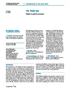
Table 3 Impedance amplitude ratios and their calculated deviations. Deviation calculated from half-bridge measurements 0.25
Electrode 55 as reference Electrode 57 as reference
D e via tio n
0.2 0.15 0.1 0.05 0
55 57 35 75 37 33 17 53 13 51 73 77 71 31
Electrode
Figure 6 Deviations of impedance amplitude ratio.
σȁݔ െ ݔ ȁଶ ܰ
This data is plotted in Figure 6. It is clear from this plot that discrimination between fault-free and faulty electrodes (no. 57 & 31) is feasible.
where for each electrode xk, xi is the distance between the impedance measurement for each electrode (i) adjacent to xk relative to the reference point, Z1 in a complex plane. Hence Dk is the defined deviation for every xk in a sample with a size of N. Due to the assumption that most electrodes have similar impedance, Dk for these electrodes will have a small deviation. On the other hand, the impedance of the “few” faulty electrodes will tend to deviate from the majority with Dk for these electrodes being relative large.
III.
APPLICATION OF OBT
The model presented in Fig. 1 has been shown to be useful for exploring the effect of surface degradation of the bio-electrodes under study. In many implementations of electrodes and electrode arrays, the value of CEDL is a function of both expected biological processes (e.g. hybridisation) and degradation mechanisms such as fouling and contamination. The Electrical Double Layer normally originates from spontaneously formed surface charge near the electrode/electrolyte interface which supports a net excess of mobile ions with a polarity opposite to that of the surface. The equilibrium is reached when sufficient charge separation is achieved at the interface. Consequently, two layers are formed at the electrode surface, namely the compact layer and the diffusion layer. Two major mechanisms appear in the electrode/electrolyte interface; capacitive effects, which dominate when voltages across the
C. Experimental Data and Associated Analysis To verify the self-test solution, experiments on the MEA have been carried out. The ratios of impedance amplitude to the reference electrode and the deviations for the 14 electrodes targeted are shown in Table 3. The reason for choosing both a faultfree electrode (no. 55) and a faulty electrode (no. 57) as the reference electrode is to demonstrate that the test results are not influenced by the selection. In both cases, we can find that the artificially damaged electrodes (no. 57 and no. 31) have higher values of Dk. These experimental results have 76
Authorized licensed use limited to: Lancaster University Library. Downloaded on November 25, 2009 at 07:25 from IEEE Xplore. Restrictions apply.
The oscillator circuit used for characterisation of the effectiveness of OBT has used values for R1, R2, and R3 of 100K, 200K and 1K respectively. The nominal value of CH is assumed to be 75pF, while CD, RD and RB are assumed to be constant because the change in electrode surface area has no effect.
interface are small (as for neural signal recording), and a resistive effect which dominates when significant current flows. Looking in more detail at the capacitive component of the Electrical Double Layer, it can be shown that CEDL can be modelled by an equivalent network consisting of CH, the compact layer capacitance, CD, the diffusion capacitance and both RD and RB the diffusion layer resistance and the bulk resistance respectively as shown in Fig. 7. The resistance effect in the compact layer has been neglected because the ions in this layer are to a first approximation immobilized.
Figure 9 CEDL integrated into the oscillation structure. This oscillator outputs a square wave at a frequency of around 20 KHz in the fault-free case, and between 20 KHz and 70 KHz dependant on the change in active area. Figure 10 and 11 show the oscillation frequency in fault-free (100% effective surface area) and faulty (25% effective surface area) cases respectively.
Figure 7 Extension of electrode model to include components of CEDL which can be replaced by CH, CD, RD and RR. The interface dominant capacitance of the EDL is CH and can be approximately expressed as CH = İHA/X1 where ɽH and X1 are the permittivity and the length of the compact capacitor (dominant capacitor) respectively, while A is the surface area of the electrode. The surface area of the electrode can be used to assess degradation because all types of degradation will affect the active area and consequently change the dominant capacitance, CH. Figure 8 shows the impact of the effective surface area of the electrode on the oscillation frequency of a test circuit where CEDL is inserted into the feedback of a standard oscillator structure shown in Figure 9. It is observed that the decrease in effective surface area of the electrode will significantly impact the oscillation frequency.
Figure 10 Oscillation frequency in fault-free case
Figure 11 Oscillation frequency in faulty case To check the effect of the other parameters in the CEDL branch on oscillation frequency, an initial exploration of the sensitivity of the method to changes in CEDL components has been carried out. All values have been swept from nominal to 50% of their values as shown in Figure 12. It is clear
Figure 8 Oscillation frequency as a function of Electrode Surface Area.
77
Authorized licensed use limited to: Lancaster University Library. Downloaded on November 25, 2009 at 07:25 from IEEE Xplore. Restrictions apply.
Dr Norbert Dumas (University Montpellier) and Prof. Hans Kerkhoff (Uni. Twente) for valuable input, and Dr Richard Heal (QinetiQ) for supplying the MEA platform.
from the figure that the dominant parameter in this branch is CH.
REFERENCES [1]
[2]
[3] [4]
Figure 12 Sweep simulations for CEDL branch. IV.
[5]
CONCLUSIONS AND FUTURE WORK
In this paper two on-line test solutions for an electrode structure have been proposed that have the potential to be built into integrated bio-fluidic systems. The low-frequency impedance method has been evaluated against data obtained from physical characterisation and the OBT method based on theoretical analysis. In comparison, while both techniques can be used to detect the same type of electrode defects, the analysis of information from the low-frequency impedance method yields a good/bad indication while the OBT technique provides an analogue value directly related to the degradation of the electrode. Although the OBT oscillator circuit intuitively appears easier to integrate than the halfbridge circuit, each electrode using the OBT method will require determination of its fault-free oscillation frequency to compensate for manufacturing variations and other parasitic capacitances. Future work will further develop pass/fail thresholds for the electrode measurements together with further investigative work into degradation mechanisms across a range of applications. Of importance will be the development of architectures for both impedance and OBT measurements compatible with integrated silicon / polymer microsystems. The integration of these techniques into a higher level control system to both provide on-line health monitoring of the electrode arrays and an architecture where defective electrodes can be switched out of the system and the array reconfigured to maintain functionality is of great interest. Of further importance is how electrode monitoring strategies can be integrated with other sensors and test solutions within a portable instrument.
[6]
[7]
[8]
[9]
[10]
[11]
[12]
[13]
[14] [15]
ACKNOWLEDGMENT
[16]
The authors would like to thank the EU FP6 Network of Excellence “Patent-DfMM” for partial support of this work in addition to the EPSRC Innovative Electronics Manufacturing Centre “I-Health” project and the FP6 “INTEGRAMplus” program. We would also like to thank
E. G. Zadeh, M, Sawan, A. Shabani, M. Zourob and V. Chodavarapu, 'Bacteria Growth Monitoring Through an On-Chip Capacitive Sensor', Proceedings of 14th IEEE International Mixed-Signal Test Workshop, June 2008, Vancouver Canada. S. Fei, K. Chakrabarty, and R. B. Fair, 'Microfluidics-Based Biochips: Technology Issues, Implementation Platforms, and DesignAutomation Challenges', IEEE Transactions on Computer-Aided Design of Integrated Circuits and Systems, vol. 25, pp. 211-223, 2006. H. G. Kerkhoff, 'Testing of Microelectronic-Biofluidic Systems', IEEE D&T for Computer, vol. 24, pp. 72-82, 2007. Hans G. Kerkhoff, 'Testing of MEMS-Based Microsystems', Proceedings of 10th IEEE European Test Symposium, pp 223-228, May 2005, Tallinn, Estonia. B. L. Gray, S. Jaffer, D. G. Sahota and S. M. Westwood, 'Mechanical and Fluidic Characterization of Microfluidic Interconnects for Labon-a-Chip Applications', Proceedings of 14th IEEE International Mixed-Signal Test Workshop, June 2008, Vancouver Canada. V. Beroulle, Y. Bertrand, L. Latorre and P. Nouet, 'Evaluation of the Oscillation-based Test Methodology for Micro-Electro-Mechanical Systems', Proceedings of 20th IEEE VLSI Test Symposium, pp 439444, April 2002, Monterey, California, USA. Hongyuan Liu, Hans G. Kerkhoff, Andrew Richardson, Xiao Zhang, Pascal Nouet and Florence Azais , 'Testing and Design of an Oscillation-Based System Architecture for DNA Sensor Array', Proceedings of 11th International Mixed-Signal Test Workshop, pp 234-239, June 2005, Cannes France. H.G. Kerkhoff , X. Zhang, H. Liu, A. Richardson P. Nouet, and F. Azais, 'VHDL-AMS Fault Simulation for Testing DNA Bio-Sensing Arrays', Proceedings of 4th IEEE Conference on Sensors, pp 10301033, October 2005, Irvine, California, USA. Hans G. Kerkhoff and Mustafa Acar, 'Testable Design and Testing of Micro-Electro-Fluidic Arrays', Proceedings of the 21st IEEE VLSI Test Symposium, pp 403-409, April 2003, Napa Valley, California, USA. Fei Su, Sule Ozev and Krishnendu Chakrabarty, 'Ensuring the Operational Health of Droplet-Based Microelectrofluidic Biosensor Systems', IEEE Sensors Journal, Vol 5, No 4, pp 763-773, August 2005. X. Zhang, F. Proosdij, and H. G. Kerkhoff, 'A Droplet Routing Technique for Fault-Tolerant Digital Microfluidic Devices', Proceedings of 14th IEEE International Mixed-Signal Test Workshop, June 2008, Vancouver Canada. Y. Zhao and K. Chakrabarty, 'Fault Diagnosis for Lab-on-Chip Using Digital Microfluidic Logic Gates', Proceedings of 14th IEEE International Mixed-Signal Test Workshop, June 2008, Vancouver Canada. H Liu, A Richardson, T Harvey, T Ryan, C Pickering “Embedded Test & Health Monitoring Strategies for Bio-Fluidic Microystems” Proceedings of the IEEE Electronic Systems Technology Conference, pp463-469, Sept. 2008, Greenwich, Gregory T. A. Kovacs, Chapter 7 in 'Enabling Technologies for Cultured Neural Networks', Academic Press, 1994, ISBN 9780126659702. 'Micro-Electrode Array (MEA) User Manual', 2005, Multi-Channel Systems, GmbH, Aspenhaustraße 21, 72770 Reutlingen, Germany, http://www.multichannelsystems.com/. Alfred Stett, Ulrich Egert, Elke Guenther, Frank Hofmann, Thomas Meyer, Wilfried Nisch and Hugo Haemmerle, 'Biological application of microelectrode arrays in drug discovery and basic research', Analytical and Bioanalytical Chemistry, Vol 377, No 3, pp 486-495, October 2003.
78
Authorized licensed use limited to: Lancaster University Library. Downloaded on November 25, 2009 at 07:25 from IEEE Xplore. Restrictions apply.