Keywords: requirements engineering, business modeling, business process ...
Business process modeling in the early phases of requirement engineering is ...
Lappeenranta University of Technology Department of Information Technology Laboratory of Information Processing
Business Process Modeling in Software Requirements Engineering for Small and Medium Software Projects Master’s Thesis
The Departmental Council of the Department of Information Technology confirmed the topic of this Master’s Thesis on 10.10.2001
Examiner: Supervisor: Instructor:
Jan Voracek, Prof. Jan Voracek Uolevi Nikula, M. Sc.
Author:
Yana Selioukova Punkkerikatu 5 B 35 53850 Lappeenranta
21.1.2002 Lappeenranta, Finland
ii
Abstract Lappeenranta University of Technology Department of Information Technology Laboratory of Information Processing Author:
Yana Selioukova
Thesis title:
Business Process Modeling in Software Requirements Engineering for Small and Medium Software Projects
Master’s thesis December 2001 Number of pages: 59 Number of figures: 16 Number of tables: 2 Examiner: Supervisor: Instructor:
Jan Voracek, Prof. Jan Voracek Uolevi Nikula, M. Sc.
Keywords: requirements engineering, business modeling, business process modeling, UML, process perspectives The goal of requirements engineering is to create a complete, consistent requirements specification of a desired system in order to establish the requirements at an abstract level. Business process modeling in the early phases of requirement engineering is rather useful. This paper examines business process modeling for the development of information systems. Today, there exist a variety of techniques for business process modeling. This Master’s thesis examines the principals and perspectives of business process modeling as well as modeling techniques. A new method, especially for small- and medium-sized software projects, was developed on the basis of process perspectives and UML diagrams.
iii
Tiivistelmä Lappeenrannan teknillinen korkeakoulu Tietotekniikan osasto Tietojenkäsittelytekniikan laitos Tekija:
Yana Selioukova
Tutkielman nimi:
Business process modeling in software requirements engineering for small and medium software projects
Diplomityö Joulukuu 2001 Sivujen lukumäärä: 59 Kuvien lukumäärä: 16 Taulukoiden lukumäärä: 2 Tarkastaja: Valvoja: Ohjaaja:
Jan Voracek, prof. Jan Voracek Uolevi Nikula, DI
Avainsanat: vaatimusmäärittelyn, liiketoiminnan mallintaminen, liiketoimintaprosessien mallintaminen, UML, prosessinäkökohdat Vaatimusmäärittelyn tavoitteena on luoda halutun järjestelmän kokonaisen, yhtenäisen vaatimusluettelon vaatimusten määrittämiseksi käsitteellisellä tasolla. Liiketoimintaprosessien mallintaminen on varsin hyödyllinen vaatimusmäärittelyn varhaisissa vaiheissa. Tämä työ tutkii liiketoimintaprosessien mallintamista tietojärjestelmien kehittämistä varten. Nykyään on olemassa erilaisia liiketoimintaprosessien mallintamiseen tarkoitettuja tekniikoita. Tämä työ tarkastaa liiketoimintaprosessien mallintamisen periaatteet ja näkökohdat sekä eri mallinnustekniikoita. Uusi menetelmä, joka on suunniteltu erityisesti pienille ja keskisuurille ohjelmistoprojekteille, on kehitetty prosessinäkökohtien ja UML-kaavioiden perusteella.
iv
Acknowledgments I would like to thank my parents, Larissa and Evgenij, for their support and the education that they provided me with and that helped me to apply for and be accepted in the International Master’s program at Lappeenranta University of Technology. I would also like to thank my husband and friend, Sergey, who is also a brilliant man, for his care, understanding and encouragement while I worked on this thesis. I acknowledge Professor Jan Voracek and the staff from Lappeenranta University of Technology for organizing the IMPIT’2000 program that gave us, the participants, a chance to obtain an excellent education and a stable future. I would like to give special thanks to Uolevi Nikula, who helped me greatly during my work, answered all my questions, helped to formulate many ideas and gave provided supervision. Our cooperation was very pleasant and beneficial. It was an honor for me to work with him. I wish to thank the Heads of the Laboratory of Information processing, professors Heikki Kälviäinen and Pekka Toivanen, for providing me with the possibility of working on my thesis in the laboratory and putting all the facilities and equipment at my disposal.
v
Abbreviations DFD - data flow diagrams ERP - enterprise resource planning OMT - object-oriented modeling and design OOSE - object-oriented software engineering QCD – quality, cost, delay SADT – structured analysis and design technique TQM – total quality management UML – unified modeling language
vi
Table of contents ABSTRACT......................................................................................................................... II TIIVISTELMÄ ..................................................................................................................III ACKNOWLEDGMENTS .................................................................................................IV ABBREVIATIONS ............................................................................................................. V TABLE OF CONTENTS ..................................................................................................VI 1.
INTRODUCTION........................................................................................................ 1
2.
INTRODUCTION TO REQUIREMENTS ENGINEERING ................................. 3 2.1. SOFTWARE REQUIREMENTS .................................................................................... 3 2.1.1. Levels of Requirements .................................................................................. 4 2.1.2. Types of Requirements ................................................................................... 6 2.1.3. Requirements characteristics......................................................................... 8 2.1.4. The Participants - the Stakeholders - of Requirements Engineering............. 9 2.2. REQUIREMENTS ENGINEERING .............................................................................. 12 2.2.1. Requirements Development ......................................................................... 13 2.2.2. Requirements Elicitation.............................................................................. 14 2.2.3. Requirements Analysis and Negotiation ...................................................... 17 2.2.4. Elicitation and Analysis Processes .............................................................. 18
3.
BUSINESS PROCESS MODELING ....................................................................... 21 3.1. BUSINESS MODELING ............................................................................................ 21 3.1.1. The Business Environment........................................................................... 21 3.1.2. Information Systems in the Modern Business World ................................... 23 3.1.3. Business Modeling ....................................................................................... 24 3.1.4. The Constituent Elements of Business Modeling ......................................... 27 3.2. BUSINESS PROCESS MODELING ............................................................................. 28 3.2.1. The Key Elements in Business Process Modeling........................................ 31 3.3. BUSINESS PROCESS MODELING IN REQUIREMENTS ENGINEERING ........................ 32 3.4. THE PERSPECTIVES OF BUSINESS PROCESS MODELING ......................................... 33
4.
BUSINESS PROCESS MODELING TECHNIQUES ........................................... 35 4.1. AN INTRODUCTION TO BUSINESS PROCESS MODELING TECHNIQUES ................... 35 4.2. STRUCTURED TECHNIQUES ................................................................................... 36 4.3. OBJECT-ORIENTED TECHNIQUES .......................................................................... 38 4.4. OBJECT-ORIENTED VERSUS STRUCTURED TECHNIQUES ....................................... 39 4.5. ACTIVITY DIAGRAMS FOR BUSINESS PROCESS MODELING ................................... 41 4.5.1. A General Overview of Activity Diagrams .................................................. 41 4.5.2. Activity Diagrams at Work........................................................................... 42
5.
A PROPOSED METHOD FOR BUSINESS PROCESS MODELING................ 45
vii 5.1. A DIAGRAM FOR THE ORGANIZATIONAL PERSPECTIVE OF A BUSINESS PROCESS . 45 5.2. DIAGRAM FOR FUNCTIONAL AND INFORMATIONAL PERSPECTIVES ON A BUSINESS PROCESS ........................................................................................................................... 47 5.3. A DIAGRAM FOR THE BEHAVIORAL PERSPECTIVE OF BUSINESS PROCESS ............ 49 5.4. CONCLUDING REMARKS FOR THE METHOD .......................................................... 51 6.
CONCLUSIONS ........................................................................................................ 53
7.
FUTURE WORK ....................................................................................................... 55
REFERENCES................................................................................................................... 56
1
1. Introduction This Master Thesis studies the field of software requirements engineering and especially that of business process modeling. Business process modeling will be examined from the point of view of software engineering and not only from a business perspective. This term can be though of in its broadest possible context. This thesis will discuss business process modeling for small- and medium- sized software projects since the approach to modeling differs in large projects [46]. The thesis is structured as follows: The role of requirements engineering is to create a complete, consistent requirement specification of the desired system in order to establish the requirements at an abstract level. Requirements engineering takes into consideration the point of view of various stakeholders and their activities in order to define useful software requirements for meeting the user’s needs. Requirements engineering provides the appropriate mechanism for understanding what the customer wants, analyzing needs, assessing feasibility, negotiating a reasonable solution, specifying the solution unambiguously, validating the specification and managing the requirements as they are transformed into an operational system [33]. Good requirements are essential for building a high quality system. They should play their role even after the project is completed, in the phases of maintenance and enhancement. Business process modeling is useful in the early phases of software development projects, especially in the phase of software requirements engineering. Several key questions concerning business process modeling are outlined below: ·
Define business modeling and its consistent parts;
·
Overview the differences between business modeling and business process modeling;
·
Identify the main reasons for using business process modeling in the software development project;
·
Represent four main perspectives on business process modeling.
2 In order to model a business process, it is necessary to consider which technique is the most suitable and which one to choose for modeling. The two most popular techniques, structured analysis and object-oriented methods, are described here and one object-oriented method, UML notation, is used for modeling. The thesis then goes on to offer a method for business process modeling originally based on process modeling perspectives and UML diagrams. Chapter 2 of the thesis concentrates on requirements engineering and proposes a general overview of the main ideas of requirements engineering: the levels and types of requirements; human factors and requirements development. In Chapter 3, the focus is on business process modeling as a consistent part of business modeling and related issues are examined. Chapter 4 is devoted to business process modeling techniques. In Chapter 5 the author presents own developed method for business process modeling based on UML diagrams and process perspectives. The conclusion reviews the key questions discussed in the thesis and discusses the proposed method.
3
2. Introduction to Requirements Engineering Before business process modeling and the role it plays in software requirements engineering can be understood it is necessary to make some basic definitions and define information of requirements engineering itself. 2.1. Software Requirements When developing software a sequence of steps must always be followed in order to accomplish a set of tasks. These steps are known as the software process or life cycle because they describe the life of a software product, starting from an uncertain concept of system functions to its implementation and further use. Versatile software life cycle models can be found in different literature resources. Some examples are: the waterfall model, V model, prototyping model, transformational model, spiral model, etc [33]. Each of them, however, contains requirements engineering as the first phase of the whole software development cycle. Many authors, such as [21, 32, 48], are of the opinion that thorough requirements are essential for building a high quality system - a system that users want. The lack of common definitions for the term “software requirements” is a problem in the software industry. Nevertheless, the IEEE standard glossary of software engineering defines requirements from both the customers’ and developers’ perspectives. Software requirements are defined by the IEEE standard glossary of software engineering terminology [19] as being: (1) a condition or capability required by a user to solve a problem or achieve an objective; (2) a condition or capability that must be met or possessed by a system or system components to satisfy a contract, standard, specification, or other formally imposed document; (3) a documented representation of a condition or capability as in 1 or 2. In other words, requirements are the features of the system that describe what the system is capable of doing in order to fulfill customer wishes. They are defined during the early stages of the software development cycle in the desired system’s requirements document an official statement of the system requirements for customers, end-users and software developers. The requirements describe the behavior and activities of the system - how the system is to act on the instructions, objects or entities and transfers from one state to another. Some examples are given below [40]:
4 1. A user-level facility (e.g. “the electronic dictionary must offer synonyms when translating from English to German and vice versa”); 2. A very general system property (e.g. “the system could log in only authorized employees”); 3. A specific constraint of the system (e.g. “the working document must be saved every 10 minutes”); 4. A constraint on the development of the system (e.g. “the system must be developed using the Oracle platform”). 2.1.1. Levels of Requirements Requirements can be identified at several levels - business, user and functional requirements – as well as various nonfunctional requirements [48]. Figure 1 [48] depicts this taxonomy.
5 Business Requirements
User Requirements
Quality Attributes Nonfunctional Requirements
System Requirements
Functional Requirements
Software requirements specification
Constraints
Figure 1. The relationship of several components of software requirements
Business requirements constitute high-level requests from users or developers to the developing system. Managers and marketing might define the business requirements for a software application that will help their company operate more efficiently or compete successfully in the marketplace. All user requirements must be in line with business requirements [48]. User requirements present a set of tasks that the user should be able to perform while working with the system. In Figure 1 user requirements are linked to quality attributes. They increase the description of the product’s functionality by presenting the characteristics of a product in various dimensions that are important to users and developers [48].
6 Functional requirements describe the interaction between the system and its environment. They are requirements that are stated in terms of inputs and outputs to the software or between elements of the software. They are a category of requirements within each level of the requirements [22]. Nonfunctional requirements describe restrictions that are imposed on the system and that limit the choices for constructing a solution to the problem [32]. These requirements can include standards, regulations and contracts to which the system must conform; design and implementation constraints and quality attributes. It could be said that nonfunctional requirements place constraints on how these functional requirements should be implemented [40]. Constraints are restrictions that are placed on the choices available to the developer for the design and construction of a software product [48]. 2.1.2. Types of Requirements The aforementioned definitions do not include the design, implementation or testing details that focus on the issue of what kind of a system is to be built. They constitute the so-called high-level requirements taxonomy. When entering in greater depth into the hierarchy, it is possible to determine types of requirements, which means that business, user, system, functional and nonfunctional requirements should be taken into consideration and that they should be included in requirements documentation. Table 1 contains information concerning types of requirements and examples of their components [32]. Table 1. Types of Requirements [32] Types of requirements Physical environment
Interfaces
Examples of components ·
Where is the equipment to function;
·
Are there more than one location;
·
Are there any environmental restrictions (temperature, humidity)?
·
Will there be input from one or more other systems;
·
Will there be output to one or more other systems;
·
Is there a prescribed way in which the data must be
7 formatted;
User and human factor
Functionality
Documentation
Data
Resources
Security
·
Is there a prescribed medium that the data must use?
·
Who will use the system;
·
Will there be several types of users;
·
What is the skill level of each type of user;
·
What kind of training will be required?
·
What and when will the system do;
·
Are there several models of operations;
·
How and when can the system be changed;
·
Are there constraints on the execution speed, response time?
·
How much documentation is required;
·
Should it be on-line, printed or both;
·
To what audience is each type of documentation addressed?
·
For both input and output, what should the format of the data be;
·
How often will it be received or sent;
·
How much data will flow through the system;
·
Must any data be retained for any period of time?
·
What material, personnel, other resources are required to build, use, and maintain the system;
·
How much physical space will be taken up by the system;
·
Is there a prescribed timetable for system development;
·
Is there a limit on the amount of money to be spent on the development or on hardware and software?
·
Must access to the system or to information be controlled;
8
Quality assurance
·
How will one user’s data be isolated from that of others;
·
Must back-up copies be stored at a different locations?
·
What are the requirements for reliability, availability, maintainability, security;
·
How must the characteristics of the system be demonstrated to others;
·
Must the system detect and isolate faults;
·
What efficiency measures will apply to resource usage and response time?
2.1.3. Requirements characteristics Requirements describe not only information flows but also focus on the constraints of the system functions. With this approach it can be said that requirements play three main roles [32]: they (1) allow developers to explain their understanding of how the customer expects the system to work; (2) tell designers what functionality and characteristics the resulting system is to possess; (3) tell the test team what to demonstrate in order to convince the customers that the delivered system is indeed what was ordered. The requirements should be of a high quality, persuading developers to make thorough use of them. Thus, it is necessary to prove that our requirements correspond with the following features/characteristics: ·
Completeness. The requirements are complete if all probable states, changes, constraints, etc are mentioned. Each requirement must fully describe the functionality to be delivered, and contain all the information necessary for the developer to design and implement that functionality [48];
·
Strict accuracy, correctness. Both sides, those of the user and the developer, should accept the requirements, which means that the errors have been disclosed [32]. The functionality of the system should also be described in detail;
9 ·
Feasibility. As the requirements are usually extracted from the users, it is necessary to verify whether the system will do exactly what users expect from it, which means verifying that the requirements can really be fulfilled by the system;
·
Consistency. Each requirement should be consistent with the overall objective for the final software product;
·
Verifiable. This refers to a set of activities that ensure that the software correctly implements a specific function [33], which means ensuring that the requirements have been successfully met. Thus, it is necessary to examine each requirement in order to consider whether a small number of tests can be devised or verification approaches, such as inspection or demonstration, used to determine whether the requirements have been properly implemented in the product [48];
·
Traceability. The ability to trace a design representation or an actual program component back to the requirements [33];
·
Necessity. Each requirement should document something that the customer really needs or something that is required for conformance to an external system requirement or standard [48].
Now when the terminology and main requirement features have been established, it is high time to move onto the so-called human factor in requirements engineering, which is a rather critical issue. 2.1.4. The Participants - the Stakeholders - of Requirements Engineering Requirements engineering is dominated by human factors since a range of people are always involved. In the broadest sense, a customer is an individual who or an organization that derives direct or indirect benefit from the final product. Software customers include those project stakeholders who request, pay for, select, specify or use a software product or who receive the output generated by the product [48]. System stakeholders are people who will be affected by the system and who have a direct or indirect influence on the system requirements [21]. It is rather typical for the customer, stakeholder and user in small- and medium-sized software projects to be the same person.
10 Wiegers specifies two kinds of customers who are responsible for different levels of requirements [48]. This division refers to the levels of requirements that were presented above: ·
Business-level requirements customer. This customer provides the high-level concept for the product and the business rationale for launching the project in the first place. These stakeholders form the business requirements, which establish a guideline framework for the rest of the project. Everything else, which is specified as a requirement, should satisfy the business requirements. These requirements are usually picked up from stakeholders who pay, procure and sponsor the project. For information systems, contract, or custom application development, business requirements should come from the establisher of the project.
·
User requirements customer. Most users belong to this type. In this case, requirements are collected from hands-on users of the product. They can describe both the tasks they need to perform on the system as well as the nonfunctional characteristics that are important for the product to be well accepted. User requirements usually come from the persons who will press the keys to use the product.
Both kinds of software customers include stakeholders with different individual and organizational goals; they may be responsible for management and may be either internal or external to an organization. Here are examples of these different types of stakeholders [21]: ·
The software engineers responsible for system development;
·
The end-user who will use the system after it has been delivered;
·
The managers of who are responsible for supervising the end-users of the system;
·
The domain experts who contribute essential background information about the system’s application domain.
11 By now the users of software and the role they play in requirement engineering have been determined, but the reason of their contribution is of great value still has not been discussed. The Standish Group published the “Chaos” report where it examined several issues [43]: the scope of software project failures; the major factors behind software project failures and the key elements that can reduce project failures. The report contains statistical data concerning users’ involvement in software projects. Here, the four most valuable features, which affect various projects, are considered in order to demonstrate the importance of user-developer communication: ·
Factors that contribute to project success: user involvement (15.9 %); executive management support (13.9 %); a clear statement of requirements (13.0 %); proper planning (9.6 %), etc.
·
Factors that challenge project success: a lack of user output (12.8 %); incomplete requirements and specification (12.3 %); changing incomplete requirements and specification (11.8 %); lack of executive support (7.5 %), etc.
·
Factors that project performance: incomplete requirements (13.1 %); lack of user involvement (12.4 %); unrealistic expectations (9.9 %); changing requirements and specification (8.7 %), etc.
The aforementioned facts were used to accentuate the point that user involvement plays an important role in the success of a software project and is an essential element in order to obtain a complete and properly functioning software system. Incomplete requirements and alterations in requirements usually become critical issues in many projects due to poor user-developer interaction.It means that a great number of projects fail because of bad requirements engineering. Those who build software programs fail miserably – 90 percent of the time – to deliver what the customers want, when they want it, at the agreed-upon price [43]. Clavadetshcer mentions: “We fail to adequately manage the software development process. User-
12 development communication breaks down; the requirements control process breaks down; we have runaway requirements, budgets, schedules, and “dead march” projects ”[5]. User involvement in a software project is more valuable than is assumed. Opinions about why projects are impaired and ultimately cancelled ranked the lack of user involvement at the top of the list [43]. It is important to work with users at the very early stages of the project in order to acquire and validate requirements and domain knowledge as effectively as possible; requirements acquisition is a totally communicative activity. Rumbaugh argues in favor of user-centered analysis, “the process of capturing requirements from the user’s point of view”, is “the best way to solve the right problem” [35]. However, even if interaction between software developers and the end-users is quite reasonable, there are still problems in the software development process. Software developers do not consider it necessary to educate and train users and stakeholders in methods and techniques used in requirements engineering [5]. The result is problems in communication and the low validity of requirements specifications. Models that describe the desired software and its notation are not understood well enough by users and stakeholders, which turns out to be a catastrophe for a project and its roots lie in the very beginning of the whole software development cycle - in the phase of requirements engineering. Previously, this thesis discussed requirements engineering without a proper explanation of the requirements engineering process and its main steps. The next section is devoted to all these questions. 2.2. Requirements Engineering Requirements engineering is a term that was invented to cover all the activities involved in discovering, documenting and maintaining a set of requirements for a computer-based system. It has a lot in common with “system analysis” - the analysis and specification of business systems - but focuses, instead, on both system and business concerns [21]. Requirements engineering provides the appropriate mechanism for understanding what the customer wants, analyzing needs, assessing feasibility, negotiating a reasonable solution, specifying the solution unambiguously, validating the specification and managing the requirements as they are transformed into an operational system [42].
13 The term “requirements engineering process” is widely used in literature [21, 40]. It is a set of tasks which are carried out to derive, validate and maintain the system requirements document [21]. The inputs to the process consist of information on the existing system, the stakeholders’ needs, organizational standards, regulations and domain information. Basically, the processes of elicitation, requirements analysis, negotiation and requirements validation that take place in requirements engineering can be referred to as the requirements engineering process. A complete process description should include what activities are to be carried out, the structuring or the scheduling of these activities, who is responsible for each activity, the inputs and outputs to or from the activity and the tools used to support requirements engineering [40]. 2.2.1. Requirements Development Requirements engineering consists of different processes that run within its framework. The requirements terminology is not clearly defined and varies from one author to another. This paper will avoid the confusion concerning the requirements vocabulary by dividing the entire area of requirements engineering into subprocesses. Figure 2 illustrates this division.
Requirements Engineering
Requirements Development
Elicitation
Analysis
Specification
Requirements Management
Verification
Figure 2. A hierarchical decomposition of requirements engineering [48]
14 Figure 2 shows that requirement engineering is divided into the phases of requirements development and software management. This Master’s thesis is devoted to the problem of business process modeling, which is used in the area of requirement’s development and especially in the elicitation and analysis subprocesses; therefore, this paper’s sphere of interest lies in these main areas of requirements engineering. 2.2.2.
Requirements Elicitation
Requirements elicitation is the process of discovering the requirements for a system by communicating with the people who have a stake in the development of the system. Basically, these requirements may not necessarily be complete and may be expressed in a vague and unstructured way [40]. System developers and engineers work with customers and end-users to determine the performance of the system, the hardware and software constraints and many other related issues. This does not involve simply asking people what they want; it requires the careful analysis of the organization, the application domain and the business processes where the system will be used [21]. Effective requirements elicitation is very important, and is not simply a process of transferring knowledge from customers or end-users to system developers and then to the specifications of the system. This task is rather complex and, if the requirements do not express real customer needs because of a poor elicitation process, the result can be project slippage or even failure. It is not easy to achieve good results in this area because there may be a wide range of stakeholders who stand to benefit in some way from the system and who use different criteria to judge the system’s acceptability [40]. In most cases, customers rarely have a clear idea of their requirements. Requirements elicitation, nevertheless, is comprehensive negotiating process that involves all the system’s stakeholders and developers and consists of four dimensions that are shown in Figure 3 [21]:
15
Requirements Elicitation
Application domain
Problem to be solved
Stakeholders’ needs and constraints
Business context
Figure 3. The components of requirements elicitation [21]
The application domain emphasizes the domain where the system is used; for example, in an accounting support system there should be some background information about accounting transactions, taxes, and bills. In problem understanding, the details of the specific customer problem, to which the system will be applied, must be understood. The objective here is to extend general domain knowledge. For the accounting support system, it must be understood, for instance, what are the principle taxes that the company has to pay and what kinds of bills are usually received. A business understanding is important in realizing how this particular system could positively influence the whole business and it components. In the case of the accounting system, attention should be given to the influence of the system on the company’s billing procedure.
16 Finally, while understanding the needs and constraints of system stakeholders it should also be remembered that they are the people for whom this system is being built. Therefore, in this phase, it is necessary to go into more details in identifying the specific needs of the customers; there must be an understanding of the working process the system will support [21]. Requirements elicitation involves all the processes mentioned above. It is a wholly cooperative process involving requirements engineers and system stakeholders. To discover all the related information requirements, engineers use different techniques [21]: ·
Interviewing is a very popular method. Interviews can be effective for developing and understanding the problem and for eliciting very general system requirements, but less effective for analyzing the application domain and the organizational issues that affect the requirements. There are, basically, two types of interviews [21]: (1) closed interviews where the requirements are extracted according to a pre-defined set of questions and (2) open interviews where there is no pre-defined agenda and which proceed in the form of a normal conversation with the stakeholders. In reality, the difference between these two types of interview is not that great.
·
Scenarios. During requirements elicitation, it is useful to create a collection of interaction scenarios for clarifying the system requirements. The scenarios could be determined as being examples of interaction sessions, which are concerned with a single type of interaction between the end-user and the system [40]. The end-users simulate their interaction using the scenario; essentially, the users explain, to the requirements engineering team, what they are doing and what information they need from the system in order to carry out the task described in the scenario [21]. Although scenarios take time to develop, this kind of requirements elicitation does not demand any greater contribution from engineers and users than do other techniques.
17 ·
Data-flow modeling, semantic data models, object-oriented approaches, etc are not that critical in the early phases of requirements engineering when the application domain and organizational requirements have to be defined. These methods provide the means for understanding abstract system requirements (the organization of knowledge according to general relationships; knowledge is described by relating specific instances to abstract structures) by analyzing the organizational context, the problems to be solved and the systems that are already in place. Nevertheless, these methods are not techniques for detailed requirements elicitation and simply help improve user-developer communication.
·
Prototyping is a quick compilation of the initial version of the system that is available at the early stages of the development cycle [21]. This means that functionality may be left out, normal management ignored, non-functional requirements less stringent, etc. There are several ways of prototyping [40], to name only two: (1) throw-away prototyping is intended to help to elicit and develop the system requirements that are the most difficult to understand; (2) an evolutionary prototype can be used to quickly deliver a workable system to the customer; thus, only well-understood requirements should be supported by the initial versions of this prototype. The principal benefit of prototyping during requirements elicitation is that it allows customers to properly visualize the desired system, to experiment with requirements and to reach the most suitable results. 2.2.3. Requirements Analysis and Negotiation
The next section will consider in detail the strong connections that exist between the processes of requirements analysis and negotiation and requirements elicitation. Their interaction is presented on Figure 4.
18 The purpose of requirements analysis and negotiation is to establish an accepted complete and consistent set of requirements. During the analysis process, missing requirements, conflicts among requirements, ambiguous requirements, overlapping requirements and unrealistic requirements are normally discovered [33]. When conflicts arise among requirements or there are ambiguous requirements proposals, stakeholders should negotiate the modification of requirements.
Elicitation
Analysis
Related processes Figure 4. The interaction between requirements elicitation and analysis Basically, requirements analysis and negotiation are activities that aim to discover the problems with system requirements and reach an agreement on changes that satisfy all system stakeholders. Some analyses are interleaved with requirements elicitation, which is the case when problems become obvious already when the requirement is expressed. However, a further analysis is usually carried out after the initial draft of the requirements document has been prepared [21]. 2.2.4. Elicitation and Analysis Processes Figure 4 shows that requirements elicitation and analysis are interconnected processes. Requirements are gathered during the elicitation process and some analysis is carried out in any case, which helps to identify current problems. The elicitation and analysis processes can, therefore, be viewed as being a spiral development model (Figure 5).
19
· · · · · ·
Step 1 Requirements elicitation; Draft statement of requirements; Requirements analysis; Requirements problems; Requirements negotiation; Requirements document
· · · · · ·
Step 2 Requirements elicitation; Draft statement of requirements; Requirements analysis; Requirements problems; Requirements negotiation; Requirements document
· · · · · ·
Step …N Requirements elicitation; Draft statement of requirements; Requirements analysis; Requirements problems; Requirements negotiation; Requirements document
Repetition of steps until appropriate solution is found and documented
Figure 5. The elicitation, analysis and negotiation spiral [40]
20
The requirements engineers elicit information from the stakeholders. This information should be analyzed to avoid unnecessary requirements and to check completeness, consistency, feasibility and correctness. After identifying all the antagonisms, software engineers negotiate all the proposed changes and improvements with the customers, which lead to another spiral round [40]. This continues until all the stakeholders are pleased with the results. Now, when all the important definitions have been presented and the various key issues both classified and clarified, this thesis can proceed onwards in the field of requirements engineering - business process modeling.
21
3. Business Process Modeling The previous chapter described, in detail, the questions related to requirements engineering and this part is devoted to business process modeling itself. Business process modeling will be examined here not only from a business perspective, but also from a software engineering perspective and can be thought of in its broadest possible sense. Business process modeling is a rather comprehensive and complex activity. First, it should be emphasized that business process modeling is an integral part of business modeling. 3.1.
Business Modeling
3.1.1. The Business Environment Running a business today under highly competitive economical conditions is not easy. Technology-induced market globalization, the demand for high-quality products that are manufactured at lower costs and developed faster, changing customer requirements as well as other internal and external factors persuade companies to adopt new rules. Companies that do not change their manufacturing, management or service strategies will find it difficult to succeed under such challenging circumstances. In other words, for many companies, staying in business means: (1) meeting customer requirements; (2) reducing the time-to-market of their products; (3) manufacturing higherquality products at lower costs. This can be summarized in three letters, QCD, which stands for quality, cost and delay (Figure 7) [46].
22
Market analysis forecasting
Sales and customer service
QCD (quality, cost, delay)
Design and engineering
Manufacturing
Figure 7. The quality-cost-delay paradigm [46] It is very difficult to produce high-quality, low-cost products at short delays because these are conflicting requirements that call for a high degree of automation and excellent management. It is also possible to describe the current business environment with the following so-called key words [46]: ·
Globalization - most companies must operate in worldwide markets;
·
Customer satisfaction – the products can be customized to meet individual specifications and must be delivered according to preset due dates;
·
Parallelization, or time-based competition refers to the simultaneous execution of a task in order to reduce time-to-x, where x represents design, engineering, manufacturing, or delivery;
·
Agility - a company must be able to react quickly to a constantly changing environment;
·
The virtual enterprise – a company may subcontract a number of its activities (or outsource) and link its information systems with those of its partner companies;
·
Total quality management (TQM) – product quality is everyone’s business, from product design to manufacturing, shipment and customer service.
23 In order to achieve these goals, business people should review and evaluate the environment in which their companies operate: the competitors, suppliers and subcontractors; internal company policy; and finally, information systems. 3.1.2. Information Systems in the Modern Business World Nowadays, the information system is an essential part of any business. A computerized information system basically consists of an information base, a set of information processes and information technology. Company managers should organize all these components in such a way that they support the company (Figure 8) [3].
THE COMPANY SYSTEM Mission, objectives, goals, strategic, plans
Business language and concepts
People, actors People who enter the process and use the information
Business processes Activities carried out by the company
External relations and conditions
Work practices How people and technology perform at work
THE COMPUTERIZED INFORMATION SYSTEM
Information base Formatted data, text, sounds
Information processes Formal procedures for information processing
Information technology Hardware, software that process information
Figure 8. The computerized information system as a part of the company [3]
24 Figure 8 clearly shows that the information system is an integral part of the daily operations of many companies. For some companies, however, the quality of the information system is not that good because it does not meet the key requirements for this system or does not provide the required support for the business [25]. In most cases, the main cause of a deficient information system is the fact that the developers of the system did not properly understand the business itself. They are driven by new technology without a vision of the business. A model of the business is of help in making the decision as to what kind of the information system is required and what place this system should occupy in the company’s structure. If the developers base the specification of the requirements on a sound business model, there is a greater chance that the information system will adequately support the business [13]. 3.1.3. Business Modeling The on-line dictionary FOLDOC [30] defines modeling as “a description of observed behavior, simplified by ignoring certain details. Models allow complex systems to be understood and their behavior predicted within the scope of the model, but may give incorrect descriptions and predictions for situations outside the realm of their intended use. A model may be used as the basis for simulation.” When considering a business approach to modeling it could be said that business modeling is an abstract form of presenting business functions and is especially suitable for an information system environment [13] (Figure 9).
25
Business model
Figure 9. A business model is a simplified view of the business [13] Figure 9 looks rather simple – people, money, facilities, etc are transformed into an abstract model that should help the normal functioning of the business. In reality, this process is much more complex. A business environment consists not only of several users and their computer interface, but, instead, of an organization, business departments, functions, networks, customers, users, human resources, inventory, management systems and more. Consequently, a business model will provide a only simplified view of the business structure and define those requirements of the information system that are necessary for running the business. The business model is the focal point around which business is conducted or around which business operations are improved. In the context of information system development, business modeling is a technique that helps answer the following question: why build the information system in the first place; where should it be located; how is it possible to determine what functionality can be optimally located in a particular information system; when should manual-processing steps or workarounds be used; when should restructuring of the organization itself be considered in order to solve the problem [25].
26 In the context of the business structure, business modeling attempts to answer the following questions: how do the business actors interact; what activities are part of their work; what are the ultimate goals of their work; what other individuals, systems or resources are involved that do not show up as actors in this specific system; what rules govern their activities and structures; are there ways in which the actors could perform more efficiently [13]. To summarize these two views in business modeling, it can be stated that the main purposes of business modeling are ·
To understand the structure and dynamics of the company; and
·
To ensure that the customers, end-users and developers possess a common understanding of the company.
Ideally, a business model should consist of one diagram that takes into account various important aspects of the business. In reality, this is impossible because a business is a rather complicated mechanism and a single diagram is not capable of holding all the necessary information. Business modeling, thus, involves a set of related diagrams. The types of diagrams and notations used depend on the chosen method/technique of modeling. The next chapter presents two techniques. Business models can, nevertheless, be totally accurate and complete, for which there are several reasons [18]: (1) the changes in a company’s environment might alter the basis on which the model was created; (2) very detailed models might become as complex as the business itself and, thereby, hard to understand; (3) stakeholders might resist overly complex models due to their intricacy; (4) not every detail can be fixed during the modeling process because each method/technique has its evident restrictions, etc. Nevertheless, in spite of the contradictions, business modeling remains a rather popular method in requirements engineering. Even with these limitations, the following arguments are still strongly in favor of producing business models [13]: ·
To better understand the key mechanism of an existing business. By providing a clear view of the roles and tasks in the overall organization, the business model can
27 be used, for example, for training staff and should help employees in various ways. In the case of capturing the requirements for the development of an information system, it is necessary to build a simple and, yet, rather detailed model in order to collect all the important requirements, avoid user-developer misunderstandings and improve user-developer interaction. On the other hand, another motive for developing any business model is to increase the understanding of the business and facilitate communication relevant to the business. ·
To act as the basis for creating a suitable system that supports the business. Descriptions of the business are used for identifying the necessary information system support. The business model is also used as the basis for specifying the key requirements of these systems.
·
To act as the basis for improving the current business structure and operation. The business model identifies current business changes that must be implemented in the improved business model. In literature, researches refer to this technique as business process re-engineering [7, 9].
There exist further motives for using business modeling but these are mostly businessoriented and are not related to requirements engineering, from the perspective of which business modeling is examined in this paper. 3.1.4. The Constituent Elements of Business Modeling Modeling of a complex business requires the use of multiple views that focus on particular aspects of the business and are described using a number of diagrams, sometimes complemented with textual documents. Eriksson and Penker [13] argue that there are four different views of a business. The author accepts their position on this division and presents these four views below [13]: ·
The business vision – an overall vision of the business. It describes the goal structure for the company and illustrates problems that must be solved in order to reach these goals;
28 ·
The business process – the view that represents the activities and value created in the business and illustrates the interaction between processes and resources;
·
The business structure – the way the resources in the business are structured, such as the organization of the business or the structure of the products created;
·
The business behavior – the individual behavior of each key resource and process in the business model.
These four views constitute the business model, although the business process view is the core of the whole model [13]. The business process view describes the process in the business along with goals, resources, and activities of the processes. Business process modeling is, thus, the most important part of business modeling in the requirements engineering context and is chosen by some authors as a requirements engineering technique for information system development [7, 13]. 3.2. Business Process Modeling The most logical point of departure for a discussion of business process modeling is to define the words in this term. The AmosWEB economics on-line dictionary defines a business as ”a profit-motivated organization that combines resources for the production and supply of goods and services. The term business is often used synonymously with the term firm. If there is any difference, and a subtle difference at that, the term business usually refers to a productive organization that is privately owned and motivated by the pursuit of profit” [29]. The second source, Merriam Webster’s on-line collegiate dictionary, determines a business as being “…a: usually commercial or mercantile activity engaged in as a means of livelihood; b: a commercial or sometimes an industrial enterprise; c: usually economic dealings” [28]. The definitions given here will be used for defining a business for the purposes of this paper. In general, the sense of the definitions will not be rejected but, rather, considered differently. In the context of requirements engineering and the different modeling
29 techniques that belong to its frameworks, it is not that important whether or not the business is profit-motivated and -oriented. This does not make any difference for the developers of information systems since they could model, for instance, a big financial corporation just as well as a public library. Consequently, the term business, in this paper, refers to any organization – profit making, not-for-profit, health-care etc. – that uses resources (human, financial, information) to produce services or products. This thesis will use the term business for all the operations that are devoted to the inter-formation of different resources required for achieving the goals of the organization. The main reason for this view is that non-commercial organizations need to be well organized and function productively, just as do commercial ones. There is a myriad of definitions for the word “process” and the most appropriate and easyto-follow definitions will be selected for use in this thesis: ·
Colin considers a process to be “a sequence of activities performed on one or more inputs to deliver an output to the customer of the process” [7];
·
On the other hand, Davenport extends the previous meaning of a process to encompass “a specific ordering of work activities across time and space, with a beginning, an end, and clearly identified inputs and outputs: a structure for action” [9];
·
Ould defines the term process according to its key features: “ (1) it contains a purposeful activity; (2) it is carried out collaboratively by a group; (3) it often crosses functional boundaries; (4) it is invariably driven by the outside world”[31].
All the aforementioned definitions of a process are accepted in this paper. The definition of modeling was given in the previous section. Finally, this paper assumes a business process to be a sequence of business activities performed by the people that exist within a company, use different resources as their inputs and produce an observable end-output and are driven by some external event or the company’s internal environment.
30 2.2.5. Business Process Modeling versus Business Modeling Of the four views of business modeling, business process modeling is the core view [13]. Business modeling and business process modeling, nevertheless, differ in many ways and to avoid confusion, the main features of business modeling as well as of business process modeling will be discussed. The previous section of this thesis presented the main goal of business modeling. To summarize the aforementioned, the main goal of business modeling is to reach an agreement among stakeholders regarding the question of “who is offering what and to whom” [16]. On the other hand, business process modeling is oriented towards understanding how activities should be carried out. Business modeling provides an idea of the overall operation of the business; business process modeling emphasizes the workflow of actions and information. According to Gordijn et al., the business process model exhibits the following design decisions [16]: who the actors involved in the company operations are; which activities can be distinguished; which activities are executed by which actors; what the inputs and outputs of activities are; what the sequence of activities is; which activities can be carried out in parallel. There are, thus, several questions that the business process model can help solve. Greenwood supposes that there exist at least three main reasons for business process modeling [17], all of which are suitable for the requirements engineering perspective. Two of these reasons will be given prioritly in this paper: ·
To describe a process. The main purpose of building a model is to obtain the following results: a definition of a process; to establish a communication link with other processes; to share the process across a group of people; to negotiate around the process. In the software requirements phase, this type of modeling can help in the very beginning when the current process model is presented to the stakeholders for their approval. It shows how accurately the developers conceive the business itself. This type of modeling allows for no mistakes in the way that business activities are understood when constructing the basis for requirements engineering.
31 ·
To analyze a process. Once a model has been built, it may be necessary to improve the quality of the model by exploring the properties of the processes themselves in order to provide support for the desired information system at the highest level. Certain analytical questions can be raised at this point; for example, what is the process life cycle and what are its bottlenecks; why is the documentation turnover so long. These questions may improve the model by [31]: changing the way in which company activities are organized; altering the responsibilities for active decisions; restructuring functions in order to align them better with the business processes; increasing and decreasing the number of parallel activities, etc. Modeling for analysis is very helpful when there is a so-called backbone model for describing processes. 3.2.1. The Key Elements in Business Process Modeling
The outcome of business process modeling is an abstraction model that is oriented towards the customer but that can help both the requirements engineers and end-users of the system to reach the main goals of modeling. In this way, the key elements of business process modeling can be formulated: ·
The abstraction of a model should be well understood by end-users. Some abstract language or notation is used for modeling, although there should not be an overload of abstraction. Models must be concrete enough to be understood and interpreted by a viewer.
·
The external business environment is unstructured; the model must be able to somehow structure it. The business process modeling approach must provide the means of summarizing and collapsing a model in a way that hides details but, at the same time, does not model what is not there.
·
Avoiding ambiguity is the rule of modeling. Usually, business process models consist of several diagrams, each of which should answer only one question.
·
Models should be oriented towards end-users. The notation must make sense to people. It is necessary to create easy-to-understand models because the model is
32 built for the end-users to elicit as many requirements as possible; overly complicated models only confuse end-users. User training is essential whenever employing a new approach. ·
Different types of modeling (As-It-Is and As-It-Should-Be). Considering a process, as-it-is, is to see what people actually do, and one of the models to be built might be based on this actual as-it-is process. When attempting to understand how the process might be redesigned in the framework of technology support, it is necessary to resolve the process in order to understand what it is effectively about [17]. In this way, it is possible to create two separate views of each process, which should help grasp the essence of the process and allow both stakeholders and developers to understand which of them is the best proceed with.
·
The usage of business process patterns is helpful and timesaving. Many of the problems that arise when modeling business processes can be solved in advance. The solution comes directly from the involvement of business process patterns in the modeling process. In general, a pattern is the description of a common solution to a recurring problem, which can be applied to a specific context [13]. 3.3. Business Process Modeling in Requirements Engineering
This section is devoted to the role of business process modeling in requirements engineering. The present-day business environment is very rigid, which means that it is hard to survive when there are many successful competitors and a lack of available resources. In this situation, companies have to optimize their functions, reduce costs and struggle for customers. These circumstances are by no means promising, but can be managed with a well-organized information system - one that handles information. Nowadays, most information systems are computerized. The word “computerized” is a reminder that software supporting an information system is to be built. Here, all the stages of the software development cycle will be applied (analysis, design, coding and testing). It is assumed, in this paper, that requirements engineering is encompassed by the analysis phase [33].
33 Business process modeling is an essential part of software requirements engineering: relevant, useful and compulsory [13]: ·
Business process modeling solves the problem of insufficient user involvement in a project by creating comprehensible models with clear notation. These models should be easily understood and close to the end-user. In the case of ambiguity, additional training should be given for the further use of the models, which the users might still experience problems in fully understanding. User involvement in the software project is more valuable than is assumed. It is important to work with users at the very early stages of the project in order to acquire and validate requirements and domain knowledge as effectively as possible; the acquisition of requirements is a totally communicative activity;
·
Business process modeling allows requirements engineers to perceive the business environment through as-it-is and as-it-should-be modeling. Both the stakeholders and developers can negotiate on which system is to be built and what process is optimal for both groups. 3.4. The Perspectives of Business Process Modeling
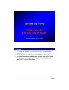
This thesis previously concentrated on requirement engineering in order to obtain a view of business process modeling. This section is devoted to views or perspectives of process modeling. This paper shares Curtis’ [8] opinion on the main perspectives of business process modeling and assumes this approach to be the core element in modeling as a whole. Curtis [8] presents four main perspectives of business process modeling: the functional, behavioral, organizational, and informational perspectives. The functional perspective illustrates what process elements are being performed and what flows of information entities are relevant to these process elements. The behavioral perspective focuses on when process elements are performed (sequencing), as well as on the aspects of the manner in which they are performed through feedback loops, interaction etc.
34 The organizational perspective shows where and by whom in the organization process elements are performed. The informational perspective illustrates the information entities that a process produces or manipulates. Each perspective can be used independently and have its own techniques and tools for implementation in a business process model; but “when combined, these perspectives will produce an integrated, consistent and complete model of process modeling” [8]. Today, there exists a great variety of modeling techniques, and choosing the most suitable method is quite difficult. On the contrary, one stands better chances of succeeding when trying out two or three of these methods and then selecting the right one or even combining several of them. Nevertheless, the key principals of modeling, as mentioned above, must be followed and the four perspectives of modeling kept in mind. The next chapter of this thesis is devoted to two techniques utilized in business process modeling as well as to a comparison of these techniques and methods.
35
4. Business Process Modeling Techniques Based on industrial experience, it can be said that, without models that are shared by the stakeholders, business is a hard activity to understand and manage. Such models must reflect the integrated, dynamic and distributed nature of the modern business [27]. There exist a great variety of techniques; the most important task is to choose the right tool in accordance with the problem in question. This chapter describes two methods for business process modeling and provides a comparison of them. 4.1. An Introduction to Business Process Modeling Techniques An understanding of the construction and functioning of a business process is a necessary precondition for many projects. For this reason, various approaches, modeling techniques and tools address the problem of the modeling of business processes. All these methods and tools have something in common: they attempt to solve a critical problem. People with very different backgrounds, such as business managers, workflow specialists, software consultants, designers and software developers, participate in the development of software solutions that support business processes. It is necessary for all the parties involved to understand the essence of the business process model through communication that spans the entire lifecycle of the project. Possessing a common language, understanding the structure and behavior of a business process, formulating the requirements in an unambiguous manner, mapping the business requirements to the software components, interpreting the business rules correctly and presenting the software solution to the users of the future system are all very important factors which determine the success or failure of a project. This chapter examines the two most used techniques for business process modeling and reaches a conclusion as to their strengths and weaknesses. Versatile classifications exist for business process modeling techniques such as given by Davis [11], Bal [2] and Wang [47]. This paper will adopt the taxonomy given by Wang who classified business process modeling techniques as following: ·
Structured;
36 ·
Object-oriented. 4.2. Structured Techniques
The structured techniques for business process modeling are related to structured programming paradigms. Several authors have developed methods for structured analysis: DeMarco [12], Yourdon [49], Gane and Sarsen [15] and others. Those three techniques are all essentially equivalent [36]. The most widely used structured analysis tool is data flow diagram (DFD). Based on DFD, SofTech Incorporated created the structured analysis and design technique (SADT) [12]. This section looks at SADT as an example of a structured analysis technique for business process modeling. The SADT uses a notation for system definition, process representation and software requirements analysis and design. It is a graphical language and a set of procedures for system analysis. However, in SADT, it is possible to combine both graphical and natural languages. A graphical language organizes a natural language in a simple and definite way. The SADT uses a non-ambiguous graphical notation in which natural language is embedded. The SADT methodology has certain distinct features: ·
Construction of the system from top to bottom. According to the purpose of a model, at each layer, it is possible to formulate the task of the layer and answer the relevant questions. The top of this tree structure presents a common description of the system, while its bottom consists of more detailed descriptions.
·
Hierarchical multilevel modeling. Obviously, at the initial stage of the construction of hierarchical models, it is possible to start with draft models. The SADT methodology allows models to be developed by adding new blocks, which contain higher-level details, without having to change the existing model.
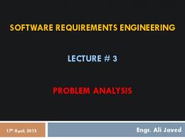
37 The main idea of the SADT methodology is the SADT block, which is presented in Figure 10. Constraints
Input
Output Functional node
Mechanism
Figure 10. SADT block SADT block is a universal unit for the universal punctuation of an unlimited but strict structure analysis. The functional node shown in Figure 10 represents an activity or a data entity. The input, which is restricted by constraints, is transformed into the output with the help of the mechanism. The output from one block can serve as the input or constraint for other blocks. Each block can be decomposed, which means that a block, as a whole, can be divided into separate components at a more detailed level. Inputs, constraints and outputs define the interfaces between blocks; mechanisms unite objects when necessary. Each diagram is composed of boxes that represent activities, which are connected by arrows that represent material, data and information flows. A model is made up of several diagrams and, thus, SADT allows the data flows between process activities to be developed and understood.
38
4.3. Object-Oriented Techniques The object-oriented approach is this paper’s second view on business process modeling. The problem domain now consists of objects, which can represent organizational units, customers, suppliers, banks etc. These objects can be manipulated using different methods, operations or services. These processing operations are part of the object and are invoked by a simple message to the object. The main category of objects can be divided into classes and subclasses. Each class contains a set of attributes that describe it and a set of operations that define its behavior. Objects inherit all the attributes and operations from their class; objects and classes encapsulate both data and processes [33], as can be seen in Figure 11. Although there is a variety of object-oriented methods [44], only the most famous ones are listed here: Booch’s object-oriented design; Coad’s and Yourdon’s object-oriented analysis and design; Rumbaugh’s object-oriented modeling and design (OMT) and Jacobson’s object-oriented software engineering (OOSE). Those methods share many concepts, but differences in terminology and notation make it quite difficult to directly compare models designed using these methods. The development of the Unified Modeling Language (UML), which provides a single standardized language for object-oriented modeling, helped to unite similar concepts by integrating ideas from three most popular methods [36]: Booch, OMT by Rumbaugh and OOSE by Jacobson.
39
Class: Customer ID Address Gender Date of last purchase Way of payment Find Contact Marketing Buy Discounting
Object: On line customer
Object: off-line customer
ID Address Gender Date of last purchase Way of payment
ID Address Gender Date of last purchase Way of payment
Find Contact Marketing Buy Discounting
Find Contact Marketing Buy Discounting
Figure 11. The process of attribute and operation inheritance from object to classes
The UML language uses one of its diagrams – the activity diagram [4] – for business process modeling. The description, main ideas and constraints of activity diagrams will be presented in section 4.5. 4.4. Object-Oriented Versus Structured Techniques This section will determine object-oriented techniques to be more acceptable than structured analysis for business process modeling as it is defined within the framework of requirements engineering during information system development. The first step in proving this idea is oriented not only towards the phase of requirements engineering but also towards the whole software development cycle. According to Pressman [33], these processes cannot be separated.
40 In the case of structured software development, problems ensue from the use of different techniques at each stage, which means that the results of each step of the development process must be converted in order to be usable in the next step [6]. Hence, procedural programs do not have very much in common with, for example, DFD that is the essence of structured analysis [36]. Object-oriented software development permits the same model to be used throughout the entire software development process [33]. The process begins with object-oriented analysis (object-oriented business process modeling in the context of this paper), converts this into an object-oriented design and proceeds with object-oriented programming. In this way, essentially the same object-oriented model that was developed at the analysis phase is later used in the program code. Secondly, this paper will consider the data and actions (processes) in these two approaches [36]. In structured analysis, it is possible to concentrate on the modeling of data or action only. In the view of Wang [47], on the other hand, separating data from action is not reasonable, since data cannot be altered without being the object of action and actions are completely meaningless without associated data. Object-oriented analysis takes into consideration both data and action; in this way, an object consists of data as well as of actions that are performed on the data. This thesis does not discuss the other advantages of the object-oriented concept, such as the reuse of objects [4]. Some authors [39] argue that there is a lack of process views and that top-down decomposition is barely supported in object-oriented techniques. On the contrary, Marshall [27] demonstrates that if a business process is too complicated and bulky to present in one diagram, it can be decomposed it into a number of sub-processes. As regards to the question of the process view, this paper assumes business process modeling to be a consistent part of business modeling. This means that business process modeling primarily and strictly emphasizes the process as it is in pure workflow modeling but, at the same time, corresponds with the overall objectives of business modeling (see Chapter 3).
41 4.5. Activity Diagrams for Business Process Modeling This paper previously mentioned that certain authors propose activity diagrams for business process modeling; see, for instance [4, 13, 45]. This section will examine activity diagrams and compare them to the principals of process modeling (see Chapter 3). Based on this analysis, the adequacy of activity diagrams for business process modeling will be reviewed. 4.5.1. A General Overview of Activity Diagrams This thesis has, all along, supported the notion that business process modeling should be customer-oriented. The primary users of activity diagrams are the stakeholders. Diagrams enable all the users to understand and monitor the development of the designed system. In general, activity diagrams are the UML diagrams that model the dynamic aspects of the system. The latest UML specification, version 1.3 [45], defines activity diagrams as mechanisms that capture business workflows, process actions and use case flows of execution. In the context of this paper, activity diagrams are examined in order to define business workflows. The activity diagram notation (see Figure 12) is used to describe processes and is organized into columns with one column for each role. The columns are also known as swimlanes. The beginning of the process is marked with a circle and the end with a bullet. An oval shows the activity of a sub-process, which usually performs different roles through events that cause them to interact (the horizontal arrows). The synchronization bar and decision activities provide the opportunity to model parallel and conditional events.
42
Figure 12. The activity diagram notation for business process modeling [27] 4.5.2. Activity Diagrams at Work Figure 13 represents an example of how the process of ordering goods can be modeled using an activity diagram. The customer places an order to the sales department. If, for some reasons, the order cannot be accepted, the request is returned to the customer (a decision activity). The engineering department prepares the design, and the production department is responsible for planning production by calculating the required amounts of each material and component and arranging their procurement by placing requests to the sales department. The production department then checks the availability of the design tools in the engineering department and confirms the tools for production. Here, two parallel processes can be identified as is shown by the synchronizing bar, which means that these processes are supposed to be finished before manufacturing process can be started. Finally, the production department manufactures the goods, which the sales department delivers to the customer.
43
Figure 13. An activity diagram of a product ordering process [27] Since the notation and mechanisms of the creation of activity diagrams have been introduced in this paper, it is possible to analyze, which aspects of business process modeling are addressed to and which aspects ignored by activity diagrams. For this purpose, it is necessary to return to Chapter 3 which discussed the main process modeling perspectives presented by Curtis [8]: functional, behavioral, organizational, and informational. This paper argues that activity diagrams address functional and informational perspectives only. According to Wang, these two perspectives correspond highly with each other [37]. An activity diagram shows what process elements are depicted, what flow of informational entities are relevant to these process elements and are produced or manipulated by the process. This activity covers both functional and informational perspectives. One can argue that, by using swimlanes, it is possible to form organizational perspectives, which emphasize to where and by whom in the organization a process element is performed, and this paper does not dispute this fact. Sorenson [41], however, mentions that the organizational perspective is oriented towards “systems communication”, which means that the organizational vision should overview business process actors not only from the
44 perspective of a single business process but also from the perspective of the overall business system. The end of this chapter deals forth with some general conclusions. Two techniques were reviewed– structural and object-oriented techniques that are used for business process modeling in the context of business modeling in requirements engineering for information system development. According to Schach, object-orientation is a superior technique because it provides the possibility to achieve cost and timesavings when developing an information system [36]. The use of the same models through the whole software development makes these savings possible. Data and action are equally important during the modeling phase in the object-oriented view; an object integrates both the data and the actions that can be applied to the data. Finally, ideas from structured analysis, such as decomposition, can be realized with the help of the object-oriented approach. Several authors have offered activity diagrams as a tool for business process modeling. Activity diagrams have been examined from process perspectives. There is no doubt that activity diagrams are a useful and necessary tool for business process modeling, but they do not reflect all four process perspectives. The next chapter will present an approach that helps to avoid this problem.
45
5. A Proposed Method for Business Process Modeling The new method for business process modeling presented herein combines three UML diagrams: use cases, activity and sequence diagrams. The main impulse for uniting these diagrams comes from the four process perspectives presented by Curtis [8]: functional, behavioral, organizational and informational. This thesis supports the idea that the joint usage of these diagrams for business process modeling addresses all the above-mentioned perspectives and creates a complete business process model. 5.1. A Diagram for the Organizational Perspective of a Business Process The previous chapter analyzed activity diagrams and assumed them to reflect only two process perspectives: functional and informational. It can be said that they also affect the organizational perspective but from a different angle. Sorenson mentioned that in the organizational view there should be an explanation of where and by whom the organization process elements are performed at a high level of abstraction [41]. Swimlanes in activity diagrams provide the following information [14]: where actions are carried out (in which object) or in which part of the organization work (an action) is performed. Hence, swimlanes can be referred to in activity diagrams at a more profound level of abstraction and consider them as being partially representative of the organizational perspective. Sorenson [41] proposes the construction of subsystem communication diagrams or organization charts for modeling business processes from the organizational point of view, but this paper considers the object-oriented methodology as the most optimal technique for business process modeling [36]. Many authors, such as [4, 14, 27], suggest the employment of use case diagrams for requirements elicitation, which is supported in this thesis. Additionally, this paper offers use case diagrams as a tool for business process modeling from the organizational perspective, since they reflect processes, actors and their interactions. Thus, in the case of business process modeling, use case diagrams help to elicit requirements as well as determine processes and the facilities used for their execution. Figure 14 shows an example of a use case diagram. The ovals which contain the name of a functionality are use cases; actors (people, facilities, etc) are represented by stick-men. This figure represents the use case diagram for request processing. It shows responsibilities and
46 the participation actions (actions of participation) of this process at a high level of abstraction.
Check status Salesperson
Place order
Customer Fill order
Shipping clerk
Manager Marketing info
Figure 14. The use case diagram for request (order) processing Jacobson et al. [20] proposed a method for object-oriented business engineering that exclusively relies on business use cases for modeling business processes. However, this paper does not accept this position. On the contrary, this paper accepts Ambler’s idea [1] according to which “use case diagram gives us a good idea as to the type of functionality the system performs, it offers no definite answer as to the order in which these use cases might occur”. Use case diagrams summarize the work steps performed in a business system (develop an overview of business processes) [37] and define the actors (participants) in business processes and thereby, contribute organizational perspective of business process modeling.
47 5.2. Diagram for Functional and Informational Perspectives on a Business Process Several authors, such as [4, 14], suggest that activity diagrams are the core of business process modeling. This paper shares this opinion. Activity diagrams, as was mentioned in Chapter 4, are oriented towards the functional and informational perspectives of the business process. Here activity diagram are used after use case diagram has been applied in order to obtain an overview of the business processes and define the main business actors with whom the system interacts. “Since a business use case model does not provide mechanism for defining the process activities and the conditions for activation of process steps, the business use case model has to be detailed by other diagrams” [37]. It is reasonable to do this using activity diagrams. Activity diagrams represent the functional and informational perspectives of business processes, which means that they concentrate on how work is performed and what information entities are produced. Figure 15 shows request processing in the purchasing department. In this diagram, all the steps of the request process are performed. The notation of activity diagrams can be found in Chapter 4. Due to technical constraints, swimlanes are not used in this diagram to divide the roles in activities. They are represented with rectangular notes on top of the figure where the actors are named. The activity diagram in this example does not concentrate much on the organizational perspective of modeling and gives rather general information about the actors of the processes, and for more detailed information, a use cases diagram is created. On the other hand, there can be situations when swimlanes provide overly detailed information about the actors of business process, which case a use case diagram is more suitable due to its more superficial presentation. Hence, use case diagrams and activity diagrams for business process modeling are mutually complementary.
Customer
Purchasing department
Warehouse
Marketing departmen t
request
create ne w order
generate order from contract
place order in work
create documentation
goods delievery confirmation
convey the order
generate order from request
check avaliability
receive goods
goods shipment
marketing information report
Figure 15. The activity diagram for request processing
49 5.3. A Diagram for the Behavioral Perspective of Business Process Already, two UML diagrams have been mapped to three business process perspectives and the behavioral perspective remains as the last connecting link for the overall model of business processes. This paper proposes to use a UML sequence diagram for the purpose of behavioral modeling, since it is necessary to define the time ordering of processes “as well as the aspects of how they are performed through feedback loops”[41]. Sequence diagrams show how objects collaborate during the process step in time and meet the requirements of behavioral perspective (see Chapter 3). However, Eriksson et al., propose the idea that the interaction between processes can also be shown on activity diagrams [13]. It is possible to use this technique, although the activity diagram may become overloaded with details and only confuse the enduser. This paper supports the notion that models should be customer-oriented; that is, why it is reasonable to develop a separate diagram that deals with the sequencing of process elements. It should be noted that a sequence diagram “should be used only to show the details of the process; the primary activities remain in the activity diagram”[13]. The Figure 15 shows the activity diagram for request processing. The sequence diagram is created based on this activity diagram (see Figure 16) and shows the chronological order of the processes that take place in the framework of request processing. Within a sequence diagram, an object is shown as a box at the top of a dashed vertical line. This line is the object’s lifeline and represents the object’s life during the course of interaction. An arrow between the lifeline and two objects shows each pass. The order in which these passes occur is from the top of the page to the bottom. A tall, thin rectangle is a period of time during which an object performs an action; its top is aligned with the start and its bottom with the completion of the action [4].
50
: Purchasing department
: Request
: Markering
: Document
make order( )
create( ) place at work( )
create document( )
convey( )
shipment( )
delivery conformation( ) reporting( )
Figure 16. A sequence diagram for request processing
: Customer
51 5.4. Concluding Remarks for the Method The new method proposed here for business process modeling consists of two main parts: the process modeling perspectives presented by Curtis [8] and the UML notation [45]. UML diagrams were mapped to process perspectives since it was considered that the object-oriented notation is optimal [47] for business process modeling (see Chapter 3) and that the usage of all process perspectives in business process modeling allows for an “integrated, consistent and complete model of the process analyzed”[8] to be produced (see Chapter 3). The proposed method unites three UML diagrams: the use case, activity and sequence diagram. Their coverage of different process perspectives is shown in Table 2. Table 2. The UML diagrams mapped to business process modeling perspectives Process modeling perspectives
UML diagrams
Organizational
Use case diagram
Functional
Activity diagram
Behavioral
Sequence diagram
Informational
Activity diagram
A use case diagram specifies the behavior of the system or a part of it, helps to elicit business processes and name the actors in the system. Thus, use case diagrams are rather well suited to the organizational perspective. However, when these diagrams are used, it is not possible to define the process and information workflows, i.e. to look at the model from the functional and informational perspective. An activity diagram is exactly what is needed for this purpose. An activity diagram shows what process elements are depicted as well as what flow of informational entities are relevant to these process elements and are produced or manipulated by the process. Activity diagrams do not, however, show the interaction between process steps and other business objects [27] that rely on the behavioral perspective and sequence diagrams. The sequence diagram is an addition to the activity diagram. The “sequence diagram specifies how a process step uses the services of other objects, by illustrating its
52 sequence, branching and looping, exceptions, and side effects” [27]. It shows only the details of a process [13], its behavioral perspective. The process step is performed by a single organizational role and only the entity properties for that role need to be modeled by a sequence diagram [27].
53
6. Conclusions This paper examined issues concerning business process modeling in requirements engineering. Business process modeling was considered as being a part of business modeling. The object-oriented approach was applied to modeling. Consequently, a new method for business process modeling was developed. The new method developed herein is based on UML diagrams and process perspectives. Three UML diagrams: use case, activity and sequencing diagrams were combined to encompass four process levels: the organizational, functional, behavioral and informational levels. A use case diagram specifies the behavior of the system or of a part of it, helps to elicit business processes and name the actors in the system. Use case diagrams are well suited to the organizational perspective. The activity diagram shows what process elements are depicted as well as what flow of informational entities are relevant to these process elements and are produced or manipulated by the process. In this way, activity diagrams are associated with the functional and informational process perspectives. Finally, the “sequence diagram specifies how a process step uses the services of other objects, by illustrating its sequence” [27]. This diagram suits the behavioral perspective. Consequently, this method combines both the object-oriented technique, which is presented in the form of UML diagrams, and the business processes paradigm, which is represented by the process perspectives. It is important to examine these two approaches together in one method for the reasons stated below: ·
Chapter 4 explained why object-oriented techniques are considered more reliable. UML is an integral [4] object-oriented method. Many companies use it in the requirements engineering phase [44]. Based on these facts, it can be said that UML is a cost-effective notation since employees are quite familiar with it and less training is needed. It is, thus, budget-friendly and useroriented. In addition, it is assumed here that several UML diagrams cover issues of process modeling.
·
The process perspectives views are important in business process modeling. This thesis accepted Curtis’ [8] approach to process modeling based on the fact that the use of all four perspectives allows for a “comprehensive,
54 unambiguous and precise ” [5] process model to be built. Otherwise, the model risks being one-sided and incomplete. The developed method is applied to small- and medium sized projects. There are other, more suitable methods for large projects, such as enterprise resource planning (ERP) system development. For further information, see [18, 26, 46].
55
7. Future work There are plans to test the proposed method in a real software engineering project. The work will be done towards method testing, discussion and evaluation.
56
References 1. Ambler, S. When to use activity diagrams: a classy example. http://www-106.ibm.com/developerworks/library/tip-whenuml/ (October, 2001) 2. Bal, J. Process analysis tools for process improvement. http://bprc.warwick.ac.uk/jay.htm (October, 2001). 3. Boman, M.; Bubenko, J., Jr., Johannesson, P.; Wangler, B. Conceptual modeling. Prentice hall, 1997. 4. Booch, G., Rumbaugn J., Jacobson I. The unified modeling language: user guide. Addison-Wesley, 1999. 5. Clavadetshcer, C. User involvement: key to success. IEEE Software, MarchApril, 1998. 6. Coad, P., Yourdon, E. Object-oriented design. Yourdon press, NJ, 1991 7. Colin, T. Business process re-engineering: myth and reality. Biddles Ltd, 1994. 8. Curtis, B., Keller, M., Over, J. Process modeling. Communications of ACM, September 1992, Vol., 35, No.9. 9. Davenport, T. Process innovation: re-engineering work through information technology. Harvard business school press, Boston, 1993. 10. Davis, A. 201 Principles of Software Development. Englewood Cliffs, NJ: Prentice-hall, 1993. 11. Davis, A. Software requirements: objects, functions, and states. Prentice Hall PTR, NJ, 1993. 12. DeMarco, T. Structured analysis and system specification. Yourdon press, NJ, 1978. 13. Eriksson, H-E, Penker, M. Business modeling with UML: business patterns at work. John Wiley & Sons, Inc, 2000. 14. Eriksson, H-E., Penker, M. UML toolkit. John Wiley & Sonc, 1998.
57 15. Gane, C., Sarten, T. Structured system analysis: tools and techniques. Prentice Hall, Englewood Cliffs, NJ, 1979. 16. Gordijn, J., Akkermans, H., Vlient van, H. Business modeling is not prosess modeling. http://www.cs.vu.nl/~gordijn (September, 2001) 17. Greenwood, M. Process terminology – a software engineering perspective. OI Pener, 2,1, Praxis plc, Bath, UK, August 1993. 18. Gulla, J., Brasethvik, T. On the challenges of business modeling in large-scale reengineering projects. http:// http://www.ieee.org (June, 2001) 19. IEEE standard glossary of software engineering terminology 610.12-1990 20. Jacobson, I., Ericsson, M., Jacobson, A. The object advantage – business process modeling with object technology. Addison-Wesley, England, 1995 21. Kotonoya, G. Sommerville, I. Requirements engineering: processes and techniques. John Wiley & Sons, NY, 1997. 22. Kovitz, B. Practical software requirements: a manual of content and style. Manning publication Co, CT, 1999. 23. Kruchten, P. The rational unified process: an introduction. Addison-Wesley, 1998. 24. Kulak, D., Guiney, E. Use cases: requirements in context. Addison-Wesley, 2000. 25. Leffingwell, D., Widrig, D. Managing software requirements. AddisonWesley, 1999. 26. Liles, D., Presley, A. Enterprise modeling within an enterprise engineering framework. 96 winter simulation conference, San Diego, CA, December. 1996 27. Marshall, C. Enterprise modeling with UML: designing successful software through business analysis. Addison-Wesley, 1999. 28. Merriam Webster’s on-line collegiate dictionary http://www.webster.com (September, 2001)
58 29. On-line dictionary AmosWEB economics, http://www.amosweb.com/gls (June, 2001) 30. On-line dictionary FOLDOC, https://www.foldoc.doc.ic.ac.uk (June, 2001) 31. Ould, M. Business processes: modeling and analysis for re-engineering and improvement. John Wiley & Sons, Inc, 1995 32. Pfleeger, S. Software engineering: Theory and Practice. Prentice-Hall, NJ, 1998. 33. Pressman, R. Software Engineering: a practitioner’s Approach. 5-th edition, McGraw-Hill, 2000. 34. Rosenberg, D., Scott, K. Use case driven object modeling with UML: practical approach. Addison-Wesley, 1999. 35. Rumbaugh, J. Getting Started: Using use cases to capture requirements. Object oriented programming journal. Sept., 1994. 36. Schach, S. Classical and object-oriented software engineering with UML and C ++. McGraw-Hill, 1998. 37. Schader, M., Korthaus, A. Modeling business processes as part of the BOOSTER approach to business object-oriented system development based on UML. http://www.ieee.org (June, 2001). 38. Schneider, G., Winters, J. Applying use cases: a practical guide. AddisonWesley, 1998. 39. Snoeck, M., Poelmans, S., Dedene, G. An architecture for bridging OO and Business process modeling. 33rd International Conference on Technology of Object-Oriented Languages, 2000. http://www.ieee.org (July, 2001) 40. Sommerville, I., Sawyer, P. Requirements engineering: a good practice guide. John Wiley & Sons, NY, 1997. 41. Sorenson, P. Process modeling presentation slides http://www.cs.ualberta.ca/~sorenson/ProMod/ProMod.ps (October, 2001)
59 42. Thayer, R., Dorfman, M. Software requirements engineering. 2-nd edition, IEEE computer society press, 1997. 43. The CHAOS Report, The Standish Group International, Inc., 1995 http://www.pm2go.com/sample_research/chaos_1994_1.asp (December, 2001) 44. The Object Agency report. A comparison of object-oriented development methodologies, 1995. http://www.toa.com/smnn?mcr.html (July, 2001) 45. UML specification http://www.rational.com/uml/index.jsp (September, 2001) 46. Vernadat, F. Enterprise modeling and integration: principles and applications. Charman & Hall, London, 1996. 47. Wang, S. Analyzing business information systems: an object-oriented approach. Auerbach, 1999. 48. Wiegers, K. Software Requirements. Microsoft press, Redmond, 1999. 49. Yourdon, E. Modern structured analysis. Yourdon press, NJ, 1989