CAD/CAPP Integration using Feature Ontology Christel Dartigues 1*, Parisa Ghodous 1, Michael Gruninger 2, Denis Pallez 1, Ram Sriram 2 1 LIRIS, University Claude Bernard of Lyon, 43, Boulevard du 11 novembre 1918 69622 Villeurbanne Cedex, FRANCE 2 NIST, 100 Bureau Drive, Gaithersburg, MD 20899-8260, USA
Abstract: In a collaborative computer-supported engineering environment, the interoperation of various applications will need a representation that goes beyond the current geometrybased representation, which is inadequate for capturing semantic information. The primary purpose of this paper is to discuss a semantically-based information exchange protocol that will facilitate seamless interoperability among current and next generation computer-aided design systems (CAD) and between CAD and other systems that use product data. We describe an ontological approach to integrating computer-aided design (CAD) and computer-aided process planning (CAPP). Two commercial software applications are used to demonstrate our approach. The approach involves the development of a shared ontology and domain-specific ontologies in the KIF (Knowledge Interchange Format) language. Domain-specific ontologies--which are feature-based—are developed after a detailed analysis of the CAD and the CAPP software. A shared ontology is generated from the domain ontologies. This shared ontology is used as a basis for mapping to and from native files of CAD/CAPP systems. The approach is validated by using a variety of parts. Keywords: CAD; CAPP; Interoperability; Ontologies; Design; Process Planning; Knowledge Interchange Format
1.
Introduction
The early part of this millennium has witnessed the emergence of an Internet-based engineering marketplace, where engineers, designers, and manufacturers from small and large companies are collaborating through the Internet to participate in various product development and marketing activities. This will be further enhanced by the next generation manufacturing environment, which will consist of a network of engineering applications, where state of the art multi-media tools and techniques will enhance closer collaboration between geographically distributed applications, virtual reality tools will allow visualization and simulation in a synthetic environment, and information exchange standards will facilitate seamless interoperation of heterogeneous applications. The interoperation of various applications will need a representation that goes beyond the current geometry-based representation, which is inadequate for capturing semantic information. The primary purpose of this paper is to discuss a semantically-based information exchange protocol that will facilitate seamless interoperability among current and next generation computer-aided design systems (CAD) and between CAD and other systems that use product data. Our focus will be on *
Corresponding author Address: Bâtiment Nautibus, Université Claude Bernard Lyon 1, 43, Boulevard du 11 novembre 1918 69622 Villeurbanne Cedex, France fax: +33 (0)4 72 43 15 36 email addresses:
[email protected],
[email protected],
[email protected],
[email protected],
[email protected]
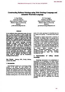
design/process planning integration during the later design stages. In this paper, we present an approach using a neutral format based on a feature ontology. Our approach involves a three stage process, as outlined below and described in detail in later sections (see Figure 1): • Stage 1: An analysis of traditional CAD (computer-aided design) and CAPP (computer-aided process planning) is performed. Based on this analysis, we identify various features used in these systems. Next, we generate formal ontologies for each of the domain. • Stage2: A shared or a common ontology for the two stated domains is developed. This shared ontology is based on the individual domain ontologies. • Stage 3: Mapping rules from the native files of the CAD and CAPP systems to and from the shared ontology are developed. These rules lead to a pragmatic implementation. In the next section we provide a brief overview of design/process planning integration. This will be followed by a discussion of representative standards for interoperating design and process planning. The need for ontological approaches is presented followed by descriptions of ontologies in the design and process planning domains. A shared ontology generated from the domain ontologies is described next. This shared ontology is used as a basis for mapping to and from native files of CAD/CAPP systems. Rules for such mappings are presented. Finally, we illustrate our approach with an example. 2.
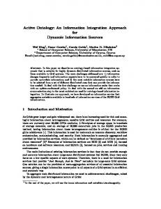
Design/Process Planning Integration: An Overview Engineering a product involves several stages with considerable iterations, starting with planning products, generating product specifications, performing preliminary and detailed design, developing process plans, building product facilities, manufacturing product, managing workflow, and finally marketing and maintaining products [1]. In this paper we focus on an important aspect of the above cycle: design and processplanning integration. We believe that it is important to integrate design and process planning at various levels of abstraction, as errors made during early design stages could have a significant impact on the overall product quality and costs [1-4]. Engineering design involves mapping a specified function (or functional specifications) onto a (description of a) realizable physical structure – the design artifact. Over the past several decades considerable research has been done in developing various design product and process models [5]. We will not delve into a detailed description of the design process, much as we feel a need for the adequate representations for process knowledge. The reader is referred to [1] for a formal description of a design process model. At this stage our primary concern is on the product or artifact representation. For this we use the NIST Core Product Model (CPM) presented in [6]. Process planning is an intermediate phase between design and manufacture [7, 8]. More precisely, it links these two decisive phases of product development [9]. It depends on choices made in design and determines precisely actions that will be achieved during
2
manufacture (Figure 2). Different definitions have been given for process planning [3, 10-12]. We use the following definition in this paper: process planning is the phase that, from information generated during design (product geometry for instance), determines: the necessary operations and actions to transform a raw part into a finished or semifinished part, the necessary human and material resources to manufacture the product, and the product development cost. A wide variety of manufacturing processes are available for the actual artifact production. In the current work we focus on the machining processes for part production, in particular material cutting processes. Figure 3 provides a representation of this process: the cutting tool comes against the surface, creating a chip that will be removed from the part. The interactions between design and process planning occur at various stages, from conceptual to detailed design/process planning as shown in Figure 4 [13]. However, it must be noted that most of the commercial tools for process planning operate on detailed geometry, although the approach presented here can be used for integrating process planning with early design stages. In other words, current interfaces between design and process planning are defined during the detailed design stage. This is primarily achieved through use of geometric features. However, there is considerable difference in the methods and terminology used: features are used to design a product (design by feature) [4, 9, 14, 15] while in process planning features are extracted from the product (design recognition or extraction) [9, 14-17], and a consistent feature terminology does not exist for the two domains. These differences are illustrated in the software used by designers and process planners: • CAD software, such as Pro/Engineer and SolidWorks, offer a limited number of features to users. The objective here is to have a compact set of parametric features, which can help designers to intuitively find more suitable features. • CAPP software, such as PART, utilizes a feature extraction algorithm and contains a large number of features. The objective here is not to have a limited set of significant features but to have a very large number of features, which can improve the efficiency of the feature extraction algorithm. These different viewpoints of designers and process planners on features makes data exchange a tedious task. Although features are considered differently in design and process planning, they represent a natural link between these two domains. Hence, features provide a valuable mechanism for information exchange. Next we review the current standards in design and process planning interoperability and discuss extensions needed for feature-based interoperability. 3.
Standards for Interoperability We illustrate the interoperability issue between CAD systems by considering a potential information exchange scenario during the design of the Boeing 777. For Boeing to incorporate Rolls Royce engines into the design, the data format has to be converted from Computer Vision’s CADDS (used by Rolls Royce) to Dassault’s CATIA. Similarly, for Rolls Royce to understand changes made by Boeing engineers, the data
3
need to be converted from CATIA to CADDS. Hence, we need at least 2 translators. For three systems this grows to 6 translators and for n systems we need n(n-1) translators. Hence, there is a need to design, build, and maintain n(n-1) translators. A solution to this problem is to use a neutral format and make all the CAD applications output this format. Doing so will reduce the number of translators to 2*n, i.e., for each CAD system we will need two translators –- one from the CAD system to the neutral format and the other from the neutral format to the CAD. A standard of primary interest to design is ISO 10303, also known informally as STEP (Standard for the Exchange of Product model data) and developed by the International Organization for Standardization Technical Committee 184/ Subcommittee SC4 (ISO TC 184/SC4). Its intention is to enable the exchange of product model data between different modules of a product realization system, or the sharing of that data by different modules through the use of a common database. The first parts of STEP to achieve International Standard status were published in 1994, but many other parts have since been published or are under development and will eventually be added to the standard. Recent updates (and other relevant details) can be found at the following websites: www.tc-184-sc4.org, and http://www.iso.ch/iso/en/ISOOnline.frontpage. ISO 10303 (STEP) consists of many parts and can be viewed as consisting of several layers. The top layer consists of a set of application protocols or APs, which address specific product classes and life-cycle stages (e.g., mechanical, electronic, ships, automotive, design, process planning). These APs specify the actual data exchange, and are constructed from a lower layer set of modules called integrated resources, which are common for all disciplines. The language for modeling various STEP entities and their relationships is called EXPRESS. Other parts specify standard mechanisms for the actual transfer of data, the conformance testing methodology, and various test suites. The primary emphasis of STEP AP 203 (STEP Application Protocol 203) is on shape description plus product configuration data. Facilities are provided for capturing, in standard format, the following representations: 3D wireframes, surface models and solid models. This reflects the state of CAD technology as it was when the STEP development effort began in the mid-1980s. However, CAD technology has progressed since that time, and most major CAD systems now provide facilities for parametric, variational design (including constraints) and/or feature-based design. In addition, many of these systems have facilities to record design histories. These systems generate additional information, beyond the pure shape descriptions created by older systems. STEP AP 203 Edition 1 did not provide any means for capturing and transmitting this additional information. The short term parametrics effort under Working Group 12 (WG 12) of ISO TC 184/SC4 is addressing this problem. WG 12’s efforts include Part 108 for parametric information and Part 111 for construction history encoding. Attempts are being made to incorporate these parts into STEP AP 203 Edition 2, which extends STEP AP 203 to the support of GD&T (geometric dimensioning and tolerancing), colors, layers, construction history, material data, etc. The technical specification document for STEP AP 203 Edition 2 was released in 2004. It is assumed that this technical specification document will reach the DIS (draft international standard) and FIS (final international standard) stages, after additional balloting.
4
Considerable research has been performed on mapping CAD data onto process planning systems. However, this work has met with limited success, such as the one reported by [18]. One problem with the current standards is the lack of integration between CAD data output and process planning input. For example, the primary focus of STEP AP 203 is the interoperability between geometry-centered CAD systems, while the focus of STEP AP 224 (Mechanical product definition for process plans using machining features) has been on input to process planning systems with a primary focus on representation of machine features. The idea of features has been in vogue for some time and the literature is abound with definitions of features [11, 15, 19-25]. For example, Shah et al. suggest that features “are primitive or low level designs with their attributes, qualifiers and restrictions which affect functionality and/or manufacturability. Features can describe form (size and shape), precision (tolerances and finishing), or materials (type, grade, properties and treatment), and vary with product and manufacturing process.” To achieve truly collaborative design and engineering, exchange representations of both design and process information must support multiple levels of abstraction. To adequately achieve this we will need a more formal method for representing features, such as the ontological approach described in the next section. Our approach has some similarities to the one presented in [26], but our overall methodology is different. 4.
Ontological Approach to Interoperability In all types of communication, the ability to share information is often hindered because the meaning of information can be drastically affected by the context in which it is viewed and interpreted. This is especially true in manufacturing, because of the growing complexity of manufacturing information and the increasing need to exchange this information among various software applications. Different representations of the same information may be based on different assumptions about the world, and use differing concepts and terminology -- and conversely, the same terms may be used in different contexts to mean different things. Often, the loosely defined natural-language definitions associated with the terms will be too ambiguous to make the differences evident, or will not provide enough information to resolve the differences. To address these challenges, various groups within industry, academia, and government have been developing sharable and reusable models known as ontologies. All ontologies consist of a vocabulary along with some specification of the meaning or semantics of the terminology within the vocabulary. In doing so, ontologies support interoperability by providing a common vocabulary with a shared semantics. Rather than develop pointto-point translators for every pair of applications, one simply needs to write one translator between the application's terminology and the common ontology. Similarly, ontologies support reusability by providing a shared understanding of generic concepts that span across multiple projects, tasks and environments. The various ontologies that have been developed can be distinguished by their degree of formality in the specification of meaning. With informal ontologies, the definitions are expressed loosely in natural language. Semi-formal ontologies, such as taxonomies, provide weak constraints for the interpretation of the terminology. Formal ontologies 5
use languages based on mathematical logic. Informal and semi-formal ontologies can serve as a framework for shared understanding among people, but they are often insufficient to support interoperability, since any ambiguity can lead to inconsistent interpretations and hence hinder integration. Another source of semantic heterogeneity lies in the languages used to represent the ontologies. There have been several efforts within academia and industry to develop common languages, such as OWL (Web Ontology Language, http://www.w3.org/TR/owl-features/) and KIF (Knowledge Interchange Format, http://www-ksl.stanford.edu/knowledge-sharing/kif/), that can be used as the basis for encoding ontologies to support semantic integration. The most expressive of these efforts is the Common Logic project, which combines the Knowledge Interchange Format [27-29] and Conceptual Graphs (CG) [30] languages. Common Logic includes a core language that has the expressiveness of first-order logic; its syntax and semantics are those of traditional first-order logic. Most recently, this has been extended to include extensions that allow sorted formulae for the specification of class hierarchies, and the specification of the meta theory of KIF within the language itself. Our objective in this paper is to demonstrate an ontological approach for data exchange between designers and process planners. To realize this, we developed a shared feature ontology, which is based on individual domain feature ontologies. This ontology represents all the common knowledge between designers and process planners. We use the shared ontology as follows: a designer creates an artifact shape model using a CAD software (such as Pro/Engineer); this model is then transformed, using CAD-files-toshared-ontology mapping rules (see Section 8), into instances of the shared ontology. These instances of the shared ontology are then transformed using shared ontology-toCAPP-files mapping rules, into a representation interpretable by CAPP software (such as PART). We assume that the CAPP software is capable of appropriate feature extraction. All ontologies in this work are expressed in KIF. In a related project we have developed the ontologies in OWL, which is aimed at representing knowledge on the Web. In that project the mappings are done between feature ontologies and the shared ontologies, rather than between native file formats and the shared ontology [31]. Computational issues associated with such mappings are currently being addressed. In the following sections, we present various feature ontologies and a description of the mapping rules used to translate data. 5.
Design Feature Ontology Our ultimate goal is to develop a comprehensive feature model that can be used through the entire design life cycle. However, for our prototype we restricted the NIST CPM’s extensions to the information generated by commercial CAD systems. To identify these concepts, we first performed an extensive analysis to understand various designers’ needs. This analysis phase involved the following: • the extraction of designer know-how--which is implicit--in order to formalize designer’s knowledge; and • the analysis of different CAD software such as Pro/Engineer and SolidWorks (we used these to create various parts in order to better understand the design
6
process). Based on this analysis we concluded that the NIST CPM had most of the necessary classes to represent detailed design data. We added a few classes in order to increase the coverage to CAD software, such as: the datum coordinate system in which the artifact is defined, the dimensions associated to an artifact, the precision of the dimensions of an artifact, the different versions of an artifact and the constraints associated to each feature. Figure 5 represents these concepts. We also defined different types of constraints as shown in Figure 6. The initial categories that we considered are position and orientation constraints, which can be further classified into attachment and geometric constraints. Attachment constraints specify how a feature instance is attached to the global model by coupling some of the feature faces with the pre-existing faces. Geometric constraints specify geometric relations such as parallelism of two faces or distance between two faces. Validity constraints correspond to another constraint category defined in our ontology. These validity constraints can be further classified into: • dimension constraints, which specify the authorized set of values for each feature parameter. e.g., radius parameter of a crossing hole can be limited to values between 1 and 10 millimeters; • algebraic constraints, which are used when feature shapes are geometrically constrained with explicit relations (these relations can be simple equalities between two parameters or, in general, algebraic expressions implying two or more of two parameters or constants); • boundary constraints, which specify if feature faces are on the boundary or not on the boundary of the conceived object; and • feature interaction constraints, which are used to indicate that a particular type of interaction is or is not allowed for a feature instance. The above extensions suffice to illustrate our approach. Additional classes will be needed for a wider coverage. KIF representations of a representative set are shown in Figure 7. 6.
Process Planning Ontology Our feature ontology is also representative of the process planning viewpoint. We followed a similar approach used for design: we asked process planners to describe how they work, what kind of information they need, what are the different phases of their work, etc. We also studied a CAPP software: PART 1 . This analysis of process planning turned out to be a more difficult task than obtaining the design features. While designers have a consistent notion of what design is, process planners seem to be in less agreement on the terminology in their domain. Based on our discussions, we decided to use the concepts presented in Figure 8.
1
http://www.opm.wb.utwente.nl/projects/part/part-doc/
7
In this figure, an artifact is associated with a manufacturing model. This model is used to create a process plan. The input of this process plan is a raw part and the output is a semi-finished or finished part. A process plan identifies the machining operations that are necessary to manufacture an artifact. Hence, a process plan is composed of machining setups, which contains all the machining operations that are realized with the same machine and without changing various attachments. For each machining setup, there is a set of machining operations. Each machining operation is then realized with the same machine and attachments. Every machining operation is composed of a set of machining sequences, which corresponds to a transformation of a part that is achieved with the help of a material removal tool moving according to a tool path. Finally, a machining operation modifies a surface in accordance to a required finish: raw, semifinish, finish or super-finish. KIF representations of a representative set are shown in Figure 9. 7.
Common Feature Ontology or Shared Ontology
Our final ontology corresponds to the common concepts between design and process planning and is composed of a number of classes and relationships. We base our ontology on the NIST Core Product Model (CPM), which was extended to deal with features identified here. Figure 10 represents the main classes and relationships composing NIST’s CPM and its extensions in this work, where the extensions are shown as darkened boxes (ideally, the NIST CPM should be a package in UML (Unified Modeling Language) and our extensions should be in a separate package). The descriptions of key entities in the NIST CPM are as follows (taken from [6]). An Artifact represents a distinct entity in a design, whether that entity is a component, product, subassembly or assembly. The Artifact’s attributes refer to the Specification responsible for the Artifact and the Form, Function, and Behavior comprising the Artifact. The Function represents what the Artifact is supposed to do. The Artifact satisfies the engineering requirements largely through its Functions. The term function is often used synonymously with the term intended behavior. The Form of the Artifact can be viewed as the proposed design solution for the design problem specified by the Functions. More precisely, the physical characteristics of an Artifact are represented in terms of its Geometry and Material properties. Another important class of the CPM is the Feature. An Artifact is composed of a set of features, where a feature is a subset of the form of an object that has some function assigned to it. We can have several types of features: analysis features, design features, manufacturing features, interface or port features, etc.. Compound features can be generated from primitive features. The notion of a feature is further elaborated in the work presented here. We modified the NIST CPM by adding some concepts that are common to design and process planning, are both necessary for designers and process planners, and are considered in CAD and CAPP software. Examples of these include: • the surfaces composing any feature; • the tolerances associated to any feature (such as the perpendicularity between
8
•
two surfaces) (a more complete treatment of tolerances and assemblies is provided in [32]); and the units used to represent any artifact.
Our main objective is to find a common feature representation between design and process planning. To do so, we extended NIST CPM to address the following: • the way each feature is represented, such as a B-Rep representation, a CSG representation, a swept representation, etc. (Feature Representation concept); and • the elements composing each feature, such as a bottom side, an intermediary face, etc. (Feature Element concept). We also characterized a complete feature decomposition which is based on the feature categories proposed in part 48 of STEP [33]. Figure 11 illustrates this decomposition. Features are classified into: • volume features, which are viewed as a volume added to or subtracted from pre-existing volume; • transition features, which are viewed as separating or blending two or more surface elements; and • pattern features, which are viewed as consisting of a number of identical sub features arranged in a mathematical pattern. Volume features can be subtractive or additive, and transition features can be corner or flat transitions. A more detailed description of this decomposition can be seen at [33, 34]. The KIF version of representative entities is shown in Figure 12. 8.
Mapping Rules For Case Study Once the feature ontologies in various domains are defined, the next step is to define the mapping rules that will transform specific files onto instances of our common ontology. For our case study, we choose the following software: Pro/Engineer, which is used by CAD experts, and PART, which is used by CAPP experts. The methodology that we followed is described in Figure 13. We first analyzed the existing export and import formats of Pro/Engineer and PART. Then, we selected one format for each of them: a proprietary format -- Neutral File Format (.PRT) -- for Pro/Engineer and the ACIS 2 format for PART. Once the formats were chosen, we analyzed the representation of different artifacts in the two formats. The objective is to extract all the important concepts represented in each file in order to correlate them with the domain ontology entities. Once this is done our approach utilizes two algorithms: one to translate a file generated by a CAD software into a set of instances of the feature ontology and one to translate this generated file into a file that can be interpreted and processed by a CAPP software. We would like the reader to note that the feature extraction is done by the CAPP software; our system only maps the shared ontology into a format that is recognized by the CAPP software. 2
http://www.spatial.com
9
The inputs to the first algorithm are: • the file containing the entire description of the ontology, which is expressed in KIF, and • the file generated by the CAD software (Pro/Engineer in this case), which represents the geometry and topology of the part that has to be manufactured.
The inputs to the second algorithm are: • the file containing the entire description of the ontology, which is the common ontology expressed in KIF, and • the file generated by the first algorithm. As we previously stated, the only assumption made during the elaboration of the ontology and the mapping rules was that we only considered parts that do not have any assembly; solving this problem for simple machining parts containing only features by itself is a difficult task. In a future work we will consider more complex parts and assemblies by using NIST’s OAM (object assembly model) [32]. If the two algorithms that we developed do not provide a “correct mapping” then: • the mapping rules implemented in the algorithms are not correct; and/or • the ontology is not correct, in which case we have to modify the ontology and then modify the mapping rules to take into account these changes. For a simple artifact such as a box with one hole (Figure 14), the file generated by Pro/Engineer is hierarchically structured: it contains the dimensions characterizing the artifact, the features used to build it, the surfaces determining the features and the edges composing the surfaces. PART files are totally different: information is stored with no specific order, and data contained in such files relates to geometric and topologic information. This kind of file format doesn’t explicitly provide information about features composing an artifact. Using different instances of Pro/Engineer and PART files, we extracted a list of entities or concepts and their attributes in these files. Example concepts are: plane surface, cylindrical surface, straight curve, linear curve, edge, point, vertex, etc. Once this analysis is done, we generated the mapping rules between a Pro/Engineer file and a file containing instances of our ontology, and between this generated file and a PART file. The purpose of these rules is to identify in our shared ontology the entities that are equivalent to the concepts that we identified in Pro/Engineer and PART native files. Initially we expressed these mapping rules graphically. In this graphical representation, we display the relationships between the attributes of the entities represented in Pro/Engineer or PART file and attributes of the entities of our ontology. Figure 15 shows the graphical representation of one such mapping rule. This mapping rule shows the correspondence between a plane surface expressed in a neutral file generated by Pro/Engineer and the equivalent concepts in our ontology. Once this step is finished, we obtained two sets of mapping rules. The next step consists in implementing these rules to be able to translate a CAD file into a CAPP file via our ontology. As we have previously stated, our method involves starting from a file
10
generated by Pro/Engineer, applying a first set of mapping rules to generate a neutral file, and then applying our second set of mapping rules on this neutral file to obtain a file interpretable by PART. A description of our mapping algorithm is shown in Figure 16. Next, we briefly describe the algorithm. Using Pro/Engineer we create all the features associated with a part. For each feature, we extract from our ontology all the attributes that we have identified for a feature (for example the list of surfaces, the list of dimensions, etc.). For each of these attributes we retrieve, still in our ontology, the nature of the attribute, which can be either simple (i.e., integer, string, boolean) or complex (i.e., the attribute is composed of sub-attributes). If the attribute is a simple one, we extract the associated value in the original file (i.e., CAD file) and we add a new instance in the neutral file. If the attribute is more complex, we consider each sub-attribute until all concepts appearing in the initial file have been instantiated. The advantage of this algorithm is that if we decide to change the attributes of one of the concepts of the ontology – for example if we delete one attribute of the concept feature -- the algorithm will not have to be modified because the number of attributes of a concept is calculated each time the algorithm is executed. In the current project our mappings were done from native file formats of commercial systems to a shared ontology. We used this approach for pragmatic reasons, in order to avoid the tedious process of application program interfaces. We also implemented a user interface for our prototype. This interface allows us to visualize the different artifacts that we considered, the Pro/Engineer file, the file generated by our prototype and containing instances of our ontology, the file in which the ontology is coded and also a graphical representation of the artifacts that we considered. Figure 17 shows a typical screen of our prototype, which is implemented at University Claude Bernard of Lyon, France (hence, the French wording). We tested our methodology and our prototype with different examples. For our initial prototype we considered only simple parts (see Figure 18), with great success. Our plans are to extend this work for complex artifacts (e.g., assemblies). The result of our approach is shown in the Figure 19.
9.
Summary In this paper we have described an ontological approach to integrating computer-aided design (CAD) and computer-aided process planning (CAPP). Two commercial software applications were used to demonstrate our approach. The approach involved the development of a shared ontology and domain-specific ontologies in the KIF (Knowledge Interchange Format) language. Domain-specific ontologies--which were feature-based--were developed after a detailed analysis of the CAD and the CAPP software. Mapping between the individual applications and the shared ontology was achieved by several mapping rules. The approach was validated by using a variety of parts.
11
10.
Acknowledgments and Disclaimer Partial funding was provided by NIST’s SIMA (Systems Integration for Manufacturing Applications) program. Sharon Kemmerer’s comments helped improve the text. The commercial software described in this paper is either trademarked or registered. No approval or endorsement of any commercial product by the National Institute of Standards and Technology or by University Claude Bernard of Lyon is intended or implied. Certain commercial equipments, instruments, or materials are identified in this report in order to facilitate better understanding. Such identification does not imply recommendations or endorsement by the National Institute of Standards and Technology or by University Bernard of Lyon, nor does it imply the materials or equipment identified are necessarily the best available for the purpose.
Bibliography 1. 2.
3.
4. 5. 6.
7.
8.
9.
10.
11.
12.
13.
Sriram R.D., Distributed and Integrated Collaborative Engineering Design. 2002. Sarven Publishers. Baker B.A., Fish R.D., Cohen E. Using a Multiple Concurrent Design Views Interface to Enhance Design Complexity Management. 2000. In ASME Design Engineering Technical Conferences (DETC). Baltimore, Maryland, USA. Feng, S.C., Song E.Y. Preliminary Design and Manufacturing Planning Integration Using Intelligent Agents. 2002. In Proceedings of the Seventh International Conference on CSCW in Design. Rio de Janeiro, Brazil. Jan de Kraker, K. Feature Conversion for Concurrent Engineering. 1998. PhD Thesis in Computer Science. Delft University of Technology, Delft, The Netherlands. Dym, C. Engineering Design: A Synthesis of Views. 1994. Cambridge University Press. New York, USA. Fenves, S.J. A Core Product Model for Representing Design Information. 2001. NISTIR 6736. National Institute of Standards and Technologies (NIST). Gaithersburg, Marylang, USA. Algeo, M.E.A. Feng, S.C., Ray, S.R. A State-of-the-Art Survey on Product Design and Process Planning Integration Mechanisms. 1994. NISTIR 5548. National Institute of Standards and Technologies (NIST). Gaithersburg, Marylang, USA. Ball M., Baras, J. Lin E., Minis, I, Nau, D., Karne, R. Integrated Product and Process Design Tool for Microwave Market. 1998. in NSF Design and Manufacturing Grantees Conference, pp. 655-656, Jan. 5-8, Monterrey, Mexico. Han, J.H., Requicha, A.A.G. Integration of Feature Based Design and Feature Recognition. 1995. in Proceedings of ASME 15th International Conference I Engineering. Boston, MA, USA. Kramer, T.R. Process Plan Expression, Generation and Enhancement for the Vertical Workstation Milling Machine in the Automated Manufacturing Research Facility at the National Bureau of Standards. 1987. NBSIR 87 – 3678. National Bureau of Standards. Gaithersburg, Maryland, USA. Regli, W.C., Pratt, M. What are Feature Interactions ? 1996. in Proceedings the 1996 ASME Design Engineering Technical Conference and Computers in Engineering Conference. Irvine, California, USA. Houten, F.J.A.M.v., Erve, A.H.v.t., Kals, H.J.J. PART a Feature Based CAPP System. 1989. in 21st CIRP International Seminar on Manufacturing Systems. Stockholm, Sweden. Feng, S.C., Song, E.Y. Information Modeling on Conceptual Design Integrated with Process Planning. 2000. in Proceedings of Symposia for Design For Manufacturability.
12
14.
15.
16.
17.
18. 19. 20.
21. 22.
23. 24. 25.
26. 27.
28.
29. 30. 31. 32.
33.
Orlando, Florida, USA. Han, J.H., Pratt, M., Regli, W.C. Manufacturing Feature Recognition from Solid Models: A Status Report. 2000. in Transactions on Robotics and Automation. 16(6). p. 782-796. Han, J.H. Survey of Feature Research. 1996. IRIS-96-346. Department of Computer Science and Institute for Robotics and Intelligent Systems, University of Southern California, USA. De Martino, T., Falcidieno, B., Hassinger, S. Design and Engineering Process Integration Through a Multiple View Intermediate Modeler in a Distributed ObjectOriented System Environment. 1998. in Computer-Aided Design. 30(6). p. 437-452. De Martino, T., Falcidieno, B., Giannini, F., Hassinger, S., Ovtcharova, J. FeatureBased Modeling by Integrating Design and Recognition Approaches. 1994. in Computer-Aided Design. 26(8). p. 646-653. Dereli, T., Filiz, H. A Note on the Use of STEP for Interfacing Design to Process Planning. 2002. in Computer-Aided Design. Vol 34. 1075-1085. Bidarra, R., Bronsvoort, W.F. Semantic Feature modeling. 2000. Computer-Aided Design. vol 32. p. 201-225. Bronsvoort, W.F., Bidarra, R., Noort, A. Semantic and Multiple-View Feature Modeling: Towards More Meaningful Product Modeling. 2001. in Geometric Modelling. Theoretical and Computational Basis towards Advanced CAD Application. Kluwer Academic Publishers, Boston, USA. 384p. Mäntylä, M., Nau, D., Shah, J.J. Challenges in Feature-Based Manufacturing Research. 1996. Communication of the ACM. 39(2). p. 77-85.. Pratt, M., Srinivasan, V. Towards a Neutral Specification of Geometric Features. 2005. in International Journal of Computer Applications in Technology. Vol 23 No 2/3/4. p. 203-218. Salomons, O.W., Houten, F.J.A.M.v., Kals, H.J.J. Review of Research in Feature Based Design. 1993. in Journal of Manufacturing Systems. 12(2). p. 113-132. Shah, J.J., Mäntylä, M. Parametric and Feature Based CAD/CAM. 1995. John Wiley & sons Inc. Edition. New York, USA. Shah, J.J., Rogers, M.T. Feature Based Modeling Shell: Design and Implementation. 1988. in Proceedings of the ASME Conference on Computer in Engineering. p. 73-86. Austin, Texas, USA. Collet, C., Huhns, M.N., Shen, W. Resource Integration Using a Large Knowledge Base in Carnot. 1991. in IEEE Computer. p. 55-62. Hayes, E.E., Menzel, C.P. A Semantics for Knowledge Interchange Format. 2001. in Working Notes of the IJCAI-2001 Workshop on the IEEE Standard Upper Ontology. Seattle, Washington, USA. Genesereth, M., Fikes, R. Knowledge Interchange Format, Version 3.0 Reference Manual. 1992. Technical Report Logic-92-1. Computer Science Department, Stanford University. Stanford, CA, USA. Genesereth, M. Knowledge Interchange Format. 2001. NCITS.T2/98-004. American National Standard (dpANS). Sowa, J.F. Glossary. 2000. http://users.bestweb.net/~sowa/ontology/gloss.htm Patil, L., Dutta, D., Sriram, R.D. Ontology-Based Exchange of Product Data Semantics. 2005. to Appear in IEEE Transactions on Automation, Science and Engineering. Sudarsan, R., Han, Y.H., Feng, S.C., Roy, U., Wang, F., Sriram, R.D., Lyons, K.W. Object-Oriented Representation of Electro-Mechanical Assemblies Using UML. 2003. NISTIR 5057, National Institute of Standards and Technologies (NIST). Gaithersburg, Maryland, USA. ISO10303-48. STEP Product Data Representation and Exchange. Integrated Generic Resources: Form Feature. 1992. International Organization for Standardization. Subcommitee 4, Part 48. NIST, Gaithersburg, Maryland, USA.
13
34.
Dartigues, C. Product Data Exchange in a Collaborative Environment. 2003. PhD Thesis in Computer Science. LIRIS, University of Lyon, Lyon, France.
14
DOMAIN SURVEY
IDENTIFICATION PHASE
Choice of Detailed Process Identification of software design expert planning expert common elements of detailed design and applications of purpose purpose the two phases process planning analysis analysis
Scenario elaboration
Determination of the ontology graphic i Determination of the ontology textual representation
PHASE
ONTOLOGY CONSTRUCTION
Determination of the ontology concepts
File with neutral Determination of the format ontology formal representation
CAD system PROTOTYPE CONSTRUCTION PHASE
Ontology of features
#UGC:2 NEUTRAL 972 440 2 0 0 15 #-VERS 0 0 #- HOST #- … 0 Neutral_part -> 1 revnum 231 1 accuracy .0012 1 outline [2][3] 2 outline [0] 3*-20 2 outline [1] 3*20 1 accuracy_is_relative 1 1 mass_props NULL 1 time_stamp -> …
CAPP system
Ontology of features
Elaboration of mapping rules from Pro/ENGINEER to the ontology
File format A
(1) Translation
Elaboration of mapping rules from the ontology to PART
(and (produit produit1) (nom_produit nomproduit1) (est_compose_de produit1 nomproduit1) (description_produit descriptionproduit1) (est_compose_de produit1 descriptionproduit1) (liste_d_assemblages listedassemblages1) (est_compose_de produit1 listedassemblages1) (= nil listedassemblages1) (liste_de_pieces listedepieces1) (est_compose_de produit1 listedepieces1) (= (length listedepieces1) 1) (liste_unites listeunites1) (est_compose_de produit1 listeunites1)
700 0 1 0 24 PART 6.1.000 07-JUN-2002 13 ACIS 7.0. NT -0 body $-1 –1 $-1 $1 $-1 $2 # -1 lump $-1 –1 $-1 $-1 $2 $0 # -2 shell $-1 –1 $-1 $-1 $-1 $3 $-1 $1 # -3 face $-1 –1 $-1 $-4 $-5 $-2 $-1 $6 reversed single # -4 face $-1 –1 $-1 $-7 $-8 $-2 $-1 $9 forward single # -5 loop $-1 –1 $-1 $10 $11 $3 # -6 cone-surface $-1 –1 $-1 –52.5 –25 129.09440602367914 0 0 1 -13
File format B
(2) Translation
Neutral Intermediary File
Figure 1: Global process for data exchange using ontologies
15
Elaboration of the shape of the product
Design
Elaboration of the machining operation necessary to manufacture the product
Execution of the operations to manufacture the product
Process Planning
Manufacture
Figure 2: Role of design, process planning and manufacturing
16
Thickness of the chip
Width of the chip
Cutting tool Manufactured surface
Vc: Cutting speed
Part
Figure 3: Representation of the material cutting process
17
Preliminary Process Planning
Conceptual Design
Process Selection
Requirement
Form/Structure & Property
Process
Functional Design
- Fabrication - Assembly - Inspection
Function
Ressource Selection
Behavioral Specification
Behavior
Estimated Time & Cost
Equipment/Skill Time & Cost Estimation
Embodiment Design
Time & Cost
Form/Structure
Detailed Process Planning
Detailed Design
-
Geometry Topology Tolerances Dimensions Surface Conditions Materials
-
Operation sequences Process parameters Setup/Fixture Accurate time & cost Manufacturing resource
Figure 4: Design and process planning interfaces
18
Artifact Version Datum Coordinate System
Surface
Units Dimension
Artifact Precision
Feature
Feature Element
Legend
Association Class Hierarchy Aggregation Design specific classes
Feature Representation
Tolerance Constraint
Figure 5: Design specific classes
19
Technologic Constraint Operation Constraint
Position and Orientation Constraint
Geometric Constraint
Constraint
Fin Constraint Economic Constraint
Attach Constraint
Splitting Validity Constraint
Disconnection Boundary Clearance Volume Clearance
Feature Interaction Boundary Constraint Algebraic Constraint
Closure Absorption Geometric Transmutation Topologic
Dimension Constraint
Figure 6: Constraint classification
20
;A constraint is the super type of: technologic constraint, ;economic constraint, validity constraint and position and ;orientation constraint. (forall (?a) (implies (constraint ?a) (or (technologic_constraint ?a) (economic_constraint ?a) (validity_constraint ?a) (position_orientation_constraint ?a)))) ;A technologic constraint is the subtype of a constraint. (forall (?a) (implies (technologic_constraint ?a) (constraint ?a))) ;A validity constraint is the subtype of a constraint. (forall (?a) (implies (validity_constraint ?a) (constraint ?a)))
Figure 7: KIF statements for constraint classification
21
Legend
Machine
Process plan
Attachment
Tool
Association Class Hierarchy Aggregation Process planning specific classes
Tool path
Machining Setup
Machining Operation
Sequence
Sub-sequence
Sequence of Machining Finishing
Raw part Manufacturing Model
Rough Semi-finishing
Semi-finished part
Finishing
Finished part
Super-finishing
Artifact
Figure 8: Process planning specific classes
22
;A manufacturing model uses a process plan (defrelation use (?a ?b):= (and (manufacturing_model ?a) (process_plan ?b))) ;Attributes of a process plan are: a set of machining setup, ; an associated manufacturing model and specifications (forall (?a) (implies (process_plan ?a) (exists (?l ?b ?c) (and (associated_manufacturing_mod el ?b) (specification ?c) (machining_setup ?l) (is_composed_of ?a ?b) (is_composed_of ?a ?c) (is_composed_of ?a ?l)))))
(forall (?a)
(implies (machining_setup ?a) (exists (?b ?c ?d ?e ?f ?g ?h ?i ?j) (and (associated_machine ?b) (associated_attachment ?c) (machining_operation_list ?d) (associated_process_plan ?e) (manufacturing_time ?f) (manufacturing_cost ?g) (manufacturing_delay ?h) (quality ?i) (operator_name ?j) (is_composed_of ?a ?b) (is_composed_of ?a ?c) (is_composed_of ?a ?d) (is_composed_of ?a ?e) (is_composed_of ?a ?f) (is_composed_of ?a ?g) (is_composed_of ?a ?h) (is_composed_of ?a ?i) (is_composed_of ?a ?j)))))
;Attributes of a machining setup are: an associated machine, an associated attachment, a list of machining operations, an associated process plan, the machining time, the cost, the delay, the quality and the operator name
Figure 9: KIF statements for feature decomposition
23
Common Co re Object
Specificatio n
Behavio r
Core entity
Core Property
Units
Surface
Artifact
Function
Feature
Form
Transfer Function
To lerance Feature Representation
Feature Element
Geometry
Legend Association Class Hierarchy Aggregation Concept added to the Core Product Model
Material
Flow
Figure 10: Main class diagram of the NIST Core Product Model and extensions
24
Feature
Pattern feature
Transition feature
Volume feature
Subtractive
Additive
Corner
Edge
Circular
Array
Other
volum e
volume
transition
transition
Feature
Feature
Feature
feature
feature
pattern
pattern
pattern
Flat
Flat
corner
edge
transition
transition
Spherical
Circular
Standalone
corner
edge
volum e
transition
transition
Depression
Protrusion
Passage
Connector
Void
1 dimensional array pattern 2 dimensional array pattern 3 dimensional array pattern
Figure 11: Feature decomposition
25
;A feature is the super type of: volume feature, ;A subtractive volume feature is a volume feature transition whose ;feature and feature pattern. ;volume is subtracted from a pre-existing volume (forall (?a) (forall (?a) (implies (feature ?a) (implies (subtractive_volume_feature ?a) (or (volume_feature ?a) (and (volume_feature?a) (transition_feature ?a) (exists (?b ?c) (feature_pattern ?a)))) (and (associated_volume ?b) (is_composed_of ?a ?b) ;A volume feature is the subtype of a feature. (pre_existing_volume ?c) (forall (?a) (subtracted ?b ?c)))))) (implies (volume_feature ?a) (feature ?a))) … … ;A void is a subtype of a subtractive volume feature ;Volume feature attributes are: associated volume and (forall (?a) ;cutting section type. (implies (void ?a) (forall (?a) (subtractive_volume_feature ?a))) (implies (volume_feature ?a) … (exists (?b ?c) (and (associated_volume ?b) (cutting_section_type ?c) (optional_attribute ?b ?a) (optional_attribute ?c ?a) (is_composed_of ?a ?b) (is_composed_of ?a ?c))))) …
Figure 12: KIF statements for feature decomposition
26
Pro/Engineer
PART
Features Surface Edges
body face edge
Analyzing concepts
Choosing of file formats
Representing mapping rules graphically Format Neutr e Surf ace (plane)
For (int i=0; i