processor. The applications are Rain detection module & LDR ... A rain sensor is a switching device. ... [4] Jong Man Jeon, Dae Won Kim, Hong Seok Kim, Yong.
International Journal of Computer Applications (0975 – 8887) Volume 150 – No.4, September 2016
CAN based Automatic Fog Light and Wiper Controller for Vehicle Bhagyashri U. Wani Department of Electronics & Telecommunication Engg. K.K.Wagh Institute of Engineering Education & Research, Nashik, Maharashtra, India
Sunita P. Ugale, PhD Department of Electronics & Telecommunication Engg. K.K.Wagh Institute of Engineering Education & Research, Nashik, Maharashtra, India
ABSTRACT As the complexity of vehicle component increases we need efficient data communication media as CAN. This system consists of different application in Vehicle automation using CAN. SAM3X8E cortex M3 processor as Master & slave processor. The applications are Rain detection module & LDR input for automatic Fog light ON-OFF & wiper movement, direction change of front light using different velocity input..
Keywords CAN, LIN, FlexRay
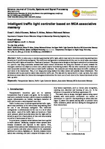
Fig 1: Standard Frame Format
1. INTRODUCTION For better performance in vehicle we require automation. Vehicle has electrical structure which consists of different ECU’s in huge number. Different ECU has different control functions. To provide high safety, more comfort, control on pollution and reduction in consumption of fuel are the requirement in vehicle. Though traditional system can accomplish main need of vehicle automation, they can’t reduce wiring complexity. For this different protocols are introduced in vehicle automation LIN, CAN, and FlexRay. Among that CAN (Controller Area Network) is most preferred.
Fig 2: Extended Frame Format RTR: it is Remote Transmission Request bit.RTR is used to detect whether the particular frame is message frame or request frame. If it is dominant (logic 0) shows a data frame. If it is recessive (logic 1) shows a remote frame.
The proposed system consists different peripherals like Rain detection sensor, Light dependent resistor, stepper motor for vehicle automation.
DLC: It is Data Length Code. It shows the length of data .
1.1 CAN protocol
CRC (cyclic redundancy check): this 15 bit field used to perform checksum over data field.
It is a Controller Area Network Bus. This bus is used to communicate between microcontrollers and devices [3]. Traditionally dedicated connection used between the component of vehicle but as the system become more complex and to make time synchronization between the components CAN protocol is used. CAN has two types of Frame Format which are Standard Frame Format & Extended Frame Format. Can Frame format: SOF bit: It is Start Of Frame. It shows the beginning of a message. It is a dominant (logic 0) bit to show message. Arbitration ID : Arbitration field consist of Identifier bits and RTR.
Data Field: It is of 8 byte.
ACK (Acknowledgement) slot: it used when CAN controller receive the message so it will send the ACK bit.
2. SYSTEM OVERVIEW The system consists of two processor of ARM core cortex 3. First processor (slave processor) takes the input from LDR for day light or night detection & rain detection sensor to detect the presence of rain. First processor sends that data over CAN bus by CAN Transreciever towards second processor (Master Processor). Second processor will take decision whether to FOG light should be made ON or OFF. This data is send towards first processor. First processor will make the light ON/OFF. Vehicle Speed switches are used to detect the speed of vehicle.
CAN message frame is of two type depending on identifier bit field. If it is 11bbit then standard frame and if 29 bit then extended format frame.
23
International Journal of Computer Applications (0975 – 8887) Volume 150 – No.4, September 2016 fringe, it connects two separated copper area which placed connection between them. Hence we can detect the presence of rain.
Fig 3: Bock diagram As per user set speed, the servo motor will move headlight such that the headlamp is in upward direction, and during slow speed headlamp will in downward direction. Temperature sensor will send data from first processor towards second processor that will be displayed over LCD.
3. HARDWARE DESIGN 3.1 LDR It is a Light Dependent Resistor or also called as a photoresistor . It is a light-controlled variable resistor. The photoresistor’s resistance decreases with increasing incident light intensity. It exhibits photoconductivity. It can be used in Light sensitive detector circuit[4]. A photoresistor is constructed by a high resistance semiconductor. In dark condition photoresistor exhibits high resistance up to several Mega ohms and in presence of light it exhibits low resistance up to few hundred ohms. If incident light on a photoresistor reaches a Particular frequency then bound electrons get energy from photons so they can reach in conduction band. The resulted free electron conduct electricity and hence lowers a resistance. Here LDR IB0276 used.
Fig 5: Rain detection sensor
3.3 Servo motor A servomotor is a closed loop servomechanism that uses position feedback to control its motion and Final position. The input to its control is some signal, either analogue or digital, representing the position commanded for the output shaft. The motor is paired with some type of encoder to provide position and speed feedback. In the simplest case, only the position is measured. The measured position of the output is compared to the command position, the external input to the controller. If the output position differs from that required, an error signal is generated which then causes the motor to rotate in either direction. This motor used to rotate the front light updown according to speed.
3.4 CAN Transreciever In this MCP2551 is used as CAN transceiver. MCP2551 is interface between a CAN protocol controller and the physical bus[2]. As it is a high-speed CAN transceiver, fault-tolerant device so mostly preferred in CAN communication. It can operate at the speeds of 1 Mb/s.
Fig 4: Light Dependent Resistor.
3.2 Rain detection sensor A rain sensor is a switching device. This is activated when rain falls on the Rain Detection sensor. This device is used to protect the interior part of an automobile from rain and used in case of the automatic mode of windscreen wipers and ON/OFF of fog light. The rain detection module design is such that single PCB copper surface cut into two parts to capture the rain drop. As soon as rain drop fall on this cutted
Fig 6: CAN Transreciever
3.5 ARM Cortex M3 RISC Processor It is 32-bit ARM Processor which is M3 RISC Cortexmicrocontroller. Operating speed of processor is 84MHz. It consists 512Kbyte of Flash and 100Kbytes of SRAM.
24
International Journal of Computer Applications (0975 – 8887) Volume 150 – No.4, September 2016 SAM3X8E has memory Protection Unit (MPU). It has 128-bit wide access.
4. SOFTWARE DESIGN 4.1 Algorithm Initialize the system first.As light Fall on LDR,the resistance is low. Make Fog light off. If not then check for rain detection module. If rain detection module shows presence of rain then fog light ON, Otherwise OFF.
5. CONCLUSION Thus use of CAN protocol gives the efficient communication between different processor which are intended for different application. The manual process of Turn ON/OFF of Fog light and windshield wiper is automated with various sensors and actuators. Experimental Setup
For the movement of stepper motor vehicle switches configure for different speed. 1)
Initializing the input and output port and CAN protocol check for vehicle speed.
2)
If the speed of vehicle is above configure speed then stepper motor will move in upward.
3)
If below configure then it move downward.
4.2 Flowchart
6. REFERENCES
Fig 7: Flowchart for automatic ON-OFF of FOG light.
[1]
S. Misbahuddin and N. Al-Holou, "Efficient data communication techniques for controller area network (CAN) protocol," Computer Systems and Applications, 2003. Book of Abstracts. ACS/IEEE International Conference on, Tunis, Tunisia, 2003, pp. 22-.
[2]
A. Lavric, V. Popa and I. Finis, "The design of a street lighting monitoring and control system," Electrical and Power Engineering (EPE), 2012 International Conference and Exposition on, Iasi, 2012, pp. 314-317.
[3]
Y. Chen et al., "A real-time vehicle safety system," System Integration (SII), 2012 IEEE/SICE International Symposium on, Fukuoka, 2012, pp. 957962.doi:10.1109/SII.2012.6427266
[4] Jong Man Jeon, Dae Won Kim, Hong Seok Kim, Yong Jo Cho and Beom Hee Lee, "An analysis of networkbased control system using CAN (controller area network) protocol," Robotics and Automation, 2001. Proceedings 2001 ICRA. IEEE International Conference on,2001,pp.3577-3581vol.4.
Fig 8: Flowchart for direction change of head light.
IJCATM : www.ijcaonline.org
25