Electrical and Electronic Engineering 2012, 2(3): 121-127 DOI: 10.5923/j.eee.20120203.03
High Speed 16×16-bit Low-Latency Pipelined Booth Multiplier Habib Ghasemizadeh*, Amir Fathi, Akbar Ghasemizadeh Department of Electrical Engineering, Salmas Branch, Islamic Azad University, Salmas, Iran
Abstract This paper presents a high-speed 16×16-bit CMOS pipelined booth multiplier. Actually in an n-bit modified Booth multiplier, because of the last sign bit, n/2 +1 partial product rows are generated rather than n/2. The extra row not only increases the delay and power consumption of Wallace tree, but also it leads to irregularity and complexity of Wallace tree designing. In this multiplier the last sign bit is removed by using a simple high-speed approach. This causes 4% reduction in power consumption and 5.2% reduction in transistor count. Also by using new partial product generation and booth encoder circuits and a novel adder, speed of pipelined multipliers is improved. By these new architectures, final adder performs 25 bit addition in only two cycles with high speed (1.6 GHz). Due to lower number of cycles (5 clock cycles), delay of the overall circuit is only 3.1ns and besides power consumption is decreased so that at a data rate of 1 GHz and under the supply voltage of 3.3V, power consumption is 169mW. This multiplier is implemented in TSMC 0.35µm CMOS technology. Keywords Carry-Select Adder, Carry-Lookahead Adder, Multiplier, Modified Booth Algorithm, Partial Products, Pipe-
line
1. Introduction Increasingly demand for high speed data processing motivated researchers to seek faster processors. Multiplier as one of the building blocks of processor has a great impact on the speed of processor, and hence high speed multipliers are under active research. Resent high speed parallel multipliers contain three sections: first part is partial product generation and a common approach for performing it is using Modified Booth Encoding (MBE) approach, Because this multiplication is signed multiplication and besides the number of rows in a n-bit multiplier are decreased to n/2 +1[1–8] rows. In the Second part partial products reduction schemes, such as Wallace trees or compressor trees are used for adding partial products vertically until, rows that were generated in part one decrease to two rows (sums and carries)[4,5]. Finally, third section is final adder that must adds two rows generated in part two, this part uses some kind of advanced adder approach such as carry-look ahead[2,10] or carry-select adders[4,5]. Any improve in each section leads to improvement in the multiplier performance. Furthermore, pipeline technique could be used for raising the speed of multiplier. But due to increasing of stages (and hence number of clock cycles) latency, high power consumption and large area are draw * Corresponding author:
[email protected] (Habib Ghasemizadeh) Published online at http://journal.sapub.org/eee Copyright © 2012 Scientific & Academic Publishing. All Rights Reserved
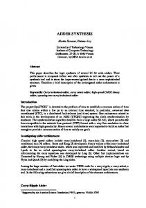
tecture of the proposed pipeline multiplier. backs of pipelined systems. Fig.1 depicts the overall archi. By using new MBE circuit and novel hybrid adder topology, not only delay of stages is decreased, but also number of cycles is reduced (Only 5 cycles), hence speed of the circuit is improved. Besides because the number of cycles is decreased, number of devices and so power consumption and die area are decreased. Bi
Ai
Booth Encoder
PPG Generator
Bi
Ai Register
Booth Encoder + PPG
Stage1
Register
4-2 Compressor
Wallace Tree
4-2 Stage2 Compressor
Register
4-2 Compressor
Stage3
Register Critical path
Final Adder (CSA/CLA)
Partial 5bit (Adder + Add One)
Stage4
Register
BCG + Sum Selector
Stage5
Register
Output
Final Output
Figure 1. Block diagram of the proposed pipelined multiplier
In the following, section 2 describes proposed MBE, section 3 explains our method of Removing the Extra Partial Product Row, section 4 discusses about Wallace tree and compressors, final adder is considered in section 5, simulation results and performance comparison are shown in section 6 and finally conclusions will be seen in the section 7.
Habib Ghasemizadeh et al.: High Speed 16×16-bit Low-Latency Pipelined Booth Multiplier
122
2. New MBE Partial Product Generation In a n-bit modified Booth multiplier number of required Booth encoders is n/2 and the number of partial product generation (PPG) circuits is approximately n2, hence power consumption and die area in the Booth section is dominated by PPG and so integration of PPG section is more important than Booth encoder (BE) block. The conventionally used modified Booth selector computes the j-th partial product bit in the i-th row (PPi,j) according to the equation 1: PPi,j = �Aj ⋅ Onei + Aj−1 ⋅ Twoi � ⊕ Neg i (1) Where Aj and Aj-1 are the multiplicand inputs of weight 2j and 2j-1 respectively. Onei and Twoi determine whether the multiplicand should be doubled, and Negi is a digit which determines if the multiplicand should be inverted. According to table.1, because Towi and Onei could not be simultaneously one, we change equation 1 to the following equation: PPi,j = �Aj ⊕ Neg i � ⋅ Onei + �Aj−1 ⊕ Neg i � ⋅ Twoi + ����� ������i ⋅ Neg i Onei ⋅ Two (2) This relationship consists of three parts that are respectively related to the area I, II and III in the table.1. Fig.2 (a) shows proposed BE and PPG sections. Table 1. Truth table for MBE B2i+1 0 0 0 0 1 1 1 1
III I II I III
B2i 0 0 1 1 0 0 1 1
B2i-1 0 1 0 1 0 1 0 1
Operation +0 +A +A +2A -2A -A -A -0
Negi 0 0 0 0 1 1 1 1 Aj
Negi
Twoi 0 0 0 1 1 0 0 0
B2i+1
Xi III
B2i B2i+1
Yib
Xib
2/2
Yi
Yib
2/2
I
Xi
1/1
II
Booth Decoder
Xib
2/2
Xi
Yi
2/2
Yib
Negi PPi,j
(a) A0 Negi A0 Xi
1/1
Negi
gnd Xib
Ki
(b)
1
Xi
1/1
Xib
K i = A0 ⋅ Onei
(3)
�����i + ��� ����� Hi = Neg i ∙ (One Neg i̇ + Onei̇ ∙ A0 A0 ) = ��������������������� (4) Figs.2 (b) and 2(c) represent circuits for generating Ki and Hi, respectively.
Aj-1
Xib B2i-1
Onei 0 1 1 0 0 1 1 0
ble.1 depicts, data is divided to three areas: in area I, Onei = Xi = b2i ⊕ b2i-1 is equal to one (equivalent to multiply by one), and middle branch of PPG conducts. in area II, Twoi =� X i ⋅ Yi =1 where Yi = b2i ⊕ b2i+1 (equivalent to multiplied by two), in this case right branch of PPG conducts and shifts the data to left side, and in area III, both Xi and Yi are zero (equivalent to multiplied by zero), and left branch handles sign’s bit (b2i+1) to the output. In two’s complement operation, sign bit (Negi=b2i+1) of each row must be added with that row. Hence this sign bit of last row cause to have 9 bit column. For having same delay for all branches, size of middle transmission gate is smaller (half) than other transmission gates. Besides by separating NMOS and PMOS devices and merging similar transistors in layout, higher speed is achievable. Function of sign changing in most of PPG circuits is performed by XOR gate, but in the proposed PPG a XNOR gate and an inverter in the output realize this function, and low driving capability of transmission gates is overcame by output inverter. Fig.3 shows well arranged structure of Wang[7] that was used in this work, but by this difference that in our structure, we didn’t use extra row omitting method of[6] and[7], because latency of omission of additional row is large and is useless in our high speed pipeline structure (table.2). In this multiplier the last sign bit (Negi) is removed by using a simple high-speed approach described in detail in the following section. Furthermore, the logic equations of Ki and Hi in Fig.3 can be derived as:
1/1
Xi
Hi
(c)
Figure 2. Proposed MBE: (a) Booth encoder and selector (PPG), (b) Proposed circuits to generate Ki and (c) Hi
As is clear from this picture PPG’s circuit consists of three branches that are constructed by transmission gate (TG). In each time only one branch is on and transmits data. For describing the circuit and explain why only one branch is on, we used truth table. For implementing equation (2), as ta-
3. Extra Partial Product Row Removing As mentioned, in Booth algorithm, the sign bit of each array (Negi=B2i+1) is added to each partial product row[6]. Doing so completes 2-complement in Booth algorithm. Addition of sign bit in the last array is same as adding an extra row to partial product rows. Generally, in an n-bit Booth multiplier, n/2 +1 partial product row will be generated. The extra row, not only increases the delay and power consumption of Wallace tree[6, 7], but it also leads to irregularity and complexity of Wallace tree designing. For example, in a 16-bit multiplier which uses compressor for reducing partial products, the extra row necessitates using eight 5-2 compressors. Whereas, in the absence of such redundant row, the whole multiplier could have functioned merely with 4-2 compressor (which is both smaller and faster[12]) as well as having a more convenient design and arrangement. This fact is more prominent in bigger multipliers since in which due to a bigger hardware, the repeating trend of blocks will affect greatly on ease of connections in layout and consequently,
Electrical and Electronic Engineering 2012, 2(3): 121-127
123
Figure 3. Architecture of proposed partial products after removing the last sign bit
Less time will be wasted on designing. In[6] structure, the duplicate integer of last array is removed which in an 8-bit multiplier leads to 13% improvement in speed and 14% improvement in power saving. Furthermore, in[7] structure, removing extra row in a 32-bit multiplier leads to 15.8% reduction of hardware and 11.7% reduction of power consumption. In[6, 7] method’s, for removing duplicate integer in the last array, the multiplicand is two’s complementation and the result is given to Booth decoder. Although[6, 7] structures are faster than conventional methods such as using CLA for two’s complementation, they are not applicable in big multipliers or high-speed pipelined ones. If we take a closer look at fig.3, we will find that instead of two’s complementation of the 16 bits of last array, some initial bits can be two’s complementation and the resultant carry will be in one of the empty spaces in higher arrays. Since the nearest empty space is in the next column of sign bit of first array (E1), therefore, at least five bits must be two’s complementation to remove extra partial product row (fig.3). Hence, in this method, independent of the number of multiplying bits, it is only needed to two’s complementation of five bits which is less delayed and needs a smaller hardware. This method has a simple structure and it is possible to design various circuits for two’s complementer section. Fig.4 depicts one of these circuits in which a 2 to 1 multiplexer and a five bit Add-one circuit is used so as to produce Booth decoder input. Add-one circuit is described in the following section.
remains. In the third cycle one row of 4:2 compressors reduce row’s number from 4 rows to 2 rows. In other Columns, depend on the situation; we used 3:2 compressors or half adder, such that less area and power be consumed. This procedure is applied to the second stage as well (fig.3). On the other hand, because simultaneous arriving of data is important in pipeline structures, we used inverters for latency matching between columns. Besides, as is depicted in fig.3 in the third stage, from column 3 to column 7, two rows exist and hence these two rows could be decreased to one row by a high speed five bits adder. Two clear advantages of this reduction is: first, for data transmission only five flip-flops are needed (rather than ten flip-flops), second and more important, final addition is reduced to 25 bits (rather than 30 bits) and so, we could achieve to response more rapidly.
4. Compression Module Among different methods and circuits that are used for adding bits by same value in a column, using parallel compressors, due to its higher speed and low area, is more usual[4,5,12]. As depicted by fig.3, eight complete rows are generated by first stage; hence we have eight rows that must be added and reduced to two rows until final adder adds these two rows and compute the last result. As is obvious from fig.1, this function is performed in second and third cycles. In the second cycle two rows of 4:2 compressors convert 8 rows to 4 rows simultaneously, so after second stage 4 rows
Figure 4. Finding two’s complement conversion signals for five bits
Theoretically 4:2 compressors that were used by[12] have latency of 3Δ, where Δ is the delay of one XOR gate. Also, Circuit of MBE (fig.2) has three gate delays, but because circuit of Booth encoder drives 16 PPG circuits, there is a big capacitor in the signal pass and hence delay of MBE circuit is slightly higher than delay of 4:2 compressors.
5. Novel Final Adder
124
Habib Ghasemizadeh et al.: High Speed 16×16-bit Low-Latency Pipelined Booth Multiplier
Among different adders, carry select adder (CSA) is known as a moderate adder, with respect to speed and die area[14]. But, some attempts were performed to improve these characteristics. For example, in[13], by the aid of an add-one circuit die area reduced by 29.2%. Also,[15, 16] by combining CLA and CSA improved speed. For the final adder, we combined these two schemes and applied changes such that the proposed structure to be compatible with pipeline structure. Fig.5 shows this adder that is realized in two cycles.
TG has a weak driving capability, so after each two or three TGs, we must use a buffer (inverter). For avoiding two cascading inverters (that has a considerable delay), we used one inverter and supplement circuit that have smaller latency. Also, as in block adders, we supposed that Cin=0, we used a half adder in the beginning of CLA, because when A1⊕B1 settles, half adder generates one bit, so in a determined time, we could add an additional bit.
Figure 5. Block diagram of the proposed pipelined final adder
As was discussed in the previous section from last three stages remained two rows that each consist of 25 bits, final adder must adds these two rows. We used five adders that each one adds 5 bits. Similar to circuit of[14], each adder is used by a five bits add-one adder with Cin=0 (rather than using a five bits adder with Cin=1). But this structure has three major difference rather than circuit of[14]. First, instead of using carry chain adder, it uses a new CLA (fig.6) for speed up. Second, inputs of add-one circuit are connected to the outputs of XOR gates (rather than outputs of partial adder); by these change inputs of add-one circuit are applied quickly and simultaneously and hence speed rises. Third, and most important, in this adder a new circuit was used for carry generation of each block, that it’s inputs are drown from blocks and hence has less hardware, whereas in[16] carry of each block is calculated from adder’s inputs. The carry-out and its complement[15] can be expressed as follows: (5) Ci = Ai ∙ Bi + (Ai ⊕ Bi ) ∙ Ci−1 � i−1 �i = A �i ∙ B �i + (Ai ⊕ Bi ) ∙ C C (6) According to equation 5 and fig.6 (a), if both Ai and Bi are one, PMOS devices of vertical branch become on and output will be one. And if both Ai and Bi are zero, NMOS devices of vertical branch become on and output carry will be zero. If only Ai or Bi is one, TG is on and Ci-1 is delivered to the output. Equation 6 and fig.6 (b) are supplement of equation 5 and fig.6 (a), respectively. Fig.6(c) shows 5 bit block adder that uses circuits of figs 6(a) and 6(b).
Figure 6. Proposed CLA circuit: (a) Ci generator cell, (b) C� i generator cell (c) 5 bit CLA.
Fig.7 depicts add-one circuit that was used in this work this circuit was proposed by[17] (except for XNOR gate that belongs to half adder). As was mentioned inputs of add-one circuit could be connected to the Ai ⊕ Bi rather than adder outputs (Si,j), because in partial adders, Cin=0 and Sis are one until Ai ⊕ Bi is one. And first Sk=0 occurs when Ak ⊕ Bk=0. After occurrence of first zero, outputs of add-one circuit become one for bit number k and later bits[15].
Figure 7. Used add-one and sum selection cell
Electrical and Electronic Engineering 2012, 2(3): 121-127
As add-one and partial adder circuits are similar, we can say the maximum delay of these circuits are almost the same. Although, number of vertical branches in block adder are twice that of add-one (and diffusion capacitance in the signal pass is higher), but delay difference between NAND and XNOR gates relaxes total delay difference. Hence in the forth cycle, 5 bit blocks that are in parallel generate Gj and Pj and Si,j bits (Fig.5).As is shown in fig.5, in fifth cycle, two functions are performed: 1)carry of each block is determined by the Block Carry Generator (BCG) cell, 2) after carry generation, final outputs are selected by Mux cells. Input carry of each block is determined by the previous block according to the equation: (7) Cj+1 = Gj + Pj ∙ Cj Fig.8 (a) shows carry generation of a block in gate level, where Cj is input carry of j-th block. Pj is the output of add-one circuit of j-th block, and Gj is the final carry out of CLA circuit of j-th block.
125
carry (Cin) of a five bit block, hence gate capacitances in the output passes of BCG is large and could impact the speed considerably. For overcoming this problem, we used minimum sized inverters for connecting output of BCG to the Mux cell of each block (fig.8(c)); hence output carry of the last blocks will be generated more rapidly. Finally, for Pipelining we used the static level sensitive latches at the output of intermediate stages that proposed in[11, 24]. It uses a transmission gate controlled by a clock signal at the input. The feedback path consists of an inverter and a transmission gate combined together to reduce power dissipation[11].
6. Simulation Results This section evaluates the performance of our newly proposed pipelined multiplier architecture and compares it with some similar works. Simulation for the multiplier design was done using HSPICE in the TSMC 0.35µm (Level 49) technology. Transistor level simulation results under the supply voltage of 3.3V and 1GHz clock frequency with 0.15ns rise/fall time, are illustrated in Table.2, Table.3 and Table.4. Table.2 shows delays of different methods to remove extra row in Modified Booth algorithm. In higher resolution multipliers our method has a constant and smaller delay (less than 0.62 ns), so it is suitable for high speed pipelined structures, as it causes 4% reduction in power consumption and 5.2% reduction in transistor count. Table 2. Delay comparisons between the proposed method and other methods (Extra row removing with 2’s Complementation)
Figure 8. Proposed BCG: (a) gate level (b)1 bit Block Carry Generator (c)5 bit Block Carry Generator
Before describing the proposed circuit, we first prove that always Pj.Gj=0, in another word, Pj and Gj are not one simultaneously. We suppose Pj=1, since Pi = (Ai ⊕ Bi ) ∙ (Ai−1 ⊕ Bi−1 ) ∙∙∙ (A1 ⊕ B1 ) ∙ (A0 ⊕ B0 ) , all multiplicands must be one, in another word, all Ai.Bi products must be zero. Since in partial adder Cin=0, so final carry out, Gj, will be zero. Now we can use circuit of fig.8 (b) instead of fig.8 (a) because it has one TG delay. As Pj.Gj=0, hence we have three situations. First Gj=1 and Pj=0, in this case TG and NMOS branches are off, but PMOS branch conducts and output will be one. Second, Gj=0 and Pj=0, in this situation TG and PMOS branches are off, but NMOS branch conducts and output will be zero,. In the third case Gj=0 and Pj=1, vertical branches are off and TG conducts. Fig.8 shows Block Carry Generator, that uses one inverter and supplement circuit similar to CLA. Because each output of BCG circuit is input
8 bit
16 bit
32 bit
64 bit
128 bit
[6] CLA (0.13um)
1.33ns
1.64ns
2.4ns
2.80ns
3.35ns
[6] (0.13um)
.47ns
.71ns
1.06ns
1.62ns
2.17ns
[7] (0.13um)
0.35ns
0.53ns
0.79ns
1.21ns
1.63ns
This Work (0.35um)
0.62ns
0.62ns
0.62ns
0.62ns
0.62ns
Also as depicted by table.3, among all cells, 5-bit CLA cell has largest delay (0.62 ns) and is the speed bottleneck of proposed pipelined multiplier. Table 3. Comparison results of each pipelined stage Stage number 1 2 3 4 5
Cell name
Cell delay (ns)
BE+PPG 5-bit 2’s complement 4:2 compressor 4:2 compressor 5-bit CLA 5-bit CLA BCG + Mux cell
0.49 0.62 0.47 0.47 0.62 0.62 0.61
Stage delay (ns) 0.62 0.47 0.62 0.62 0.61
Finally, table.4 shows some characteristics of the circuit and comparison with similar structures. Note that reference 3 is in gate level, hence for counting the number of transistors,
Habib Ghasemizadeh et al.: High Speed 16×16-bit Low-Latency Pipelined Booth Multiplier
126
we assumed each gate consist 4 transistors (4*8246=32984). Our multiplier performs the operation with 5 clock cycles, and can operate at 1.6 GHz. Total transistor number in the proposed multiplier is 9221 and the average power consumption is only 169 mW as operating at 3.3V, 1 GHz corresponding to the input pattern with 31.02% transition probability. Table 4. Comparison with some similar works
Process (µm) Input bits Supply voltage Fmax (GHz) Number of stages Average Power @1GHz (mW) Transistor count
[1]
[2]
[3]
[9]
This work
0.35 8×8 3.3v 1 14
0.35 8×8 3.3v 1.2 6
0.13 16×16 1.2v 2.63 16
0.35 8×8 3.3v 1.2 17
0.35 16×16 3.3v 1.6 5
100.52
60.18
-
153
169
4812
3287
32984
-
9221
7. Conclusions Due to importance of multipliers in signal processing we designed a high speed low power 16×16-bit pipelined booth multiplier. In this multiplier the last sign bit is removed by using a simple high-speed approach that causes 4% reduction in power consumption and 5.2% reduction in transistor count. Also by using new partial product generation and booth encoder circuits speed of first stages (partial product generation) is increased and with a novel adder multiplication is performed in five cycles. Theoretically number of partial products in a 16×16-bit multiplier is fourth that of an 8×8-bit multiplier. This factor is a good measure for comparison of power consumption and number of transistors between these two multipliers. Table.4 compares some characteristics of this multiplier with other similar works.
REFERENCES
Booth Multiplier Utilizing Multiplexer-Select Booth Encoder,” ASICON. 6th Int. Conf, vol. 1, pp. 57-60, Oct. 2005. [6]
J. Y. Kang and J. L. Gaudiot, “A Simple High-Speed Multiplier Design,” IEEE Trans. Computers, vol. 55, p.p. 1253-1257, 2006.
[7]
L.R. Wang, S.J. Jou and C.L. Lee, “A well-structured modified Booth multiplier design,” Proc. of IEEE VLSI-DAT, pp. 85-88, April. 2008.
[8]
S. Hsu, S. Mathew, M. Anders, B. Bloechel, R. Krishnamurthy, S. Borkar, “A 110GOPS/W 16b Multiplier and Reconfigurable PLA Loop in 90nm CMOS,” IEEE ISSCC Dig. Tech. Papers, pp. 376-377, 2005.
[9]
M.A. Hernandez and M.L. Aranda, “Energy-efficient high-speed CMOS pipelined multiplier,” Proc. of IEEE CCE, pp. 460-464, Nov. 2008.
[10] A. Khatibzadeh, K. Raahemifar, “A novel design of a 6-GHz 8x8 bit pipelined multiplier,” Proc. 9th Int. Conf. on Database Engineering and Application Symposium (IDEAS’05), pp. 1–5, 2005. [11] P. Ramanathan, P.T. Vanathi, and S. Agarwal, “High Speed Multiplier Design Using Decomposition Logic,” Serbian Journal of Electrical Engineering, vol. 6, no. 1,pp. 33-42, May 2009. [12] C. H. Chang, J. Gu, and M. Zhang, “Ultra low voltage, low power CMOS 4-2 and 5-2 compressors for fast arithmetic circuits,” IEEE Trans. Circuits Syst. I, Reg. Papers, vol. 51, no. 10, pp. 1985–1997, Oct. 2004. [13] T. Y. Chang and M. J. Hsiao, “Carry-select adder using single ripple-carry adder,” Electron. Lett., vol. 34, no. 22, pp. 2101–2103, Oct. 1998. [14] Y. Kim and L. S. Kim, “64-bit carry-select adder with reduced area,” Electron. Lett., vol. 37, no. 10, pp. 614–615, May 2001. [15] G.A. Ruiz, M. Granda, “An area-efficient static CMOS carry-select adder based on a compact carry look-ahead unit,” Microelectronics Journal, vol. 35, no. 12, pp. 939-944, 2004. [16] Y. Wang, C. Pai, and X. Song, “The design of hybrid carry-lookahead/carry-select adders,” IEEE Trans. Circuits Syst. II, Analog Digit. Signal Process. vol. 49, no. 1, pp. 16–24, Jan. 2002. [17] Y. He and C.H. Chang, “A Power-Delay Efficient Hybrid Carry-Lookahead/Carry-Select Based Redundant Binary to Two's Complement Converter,” IEEE Trans. Circuits Syst. I, Reg. Papers, vol. 55, no. 1, pp. 336 - 346, Feb. 2008.
[1]
H.C. Chow and I.C. Wey, “A 3.3V 1GHz high speed pipelined Booth multiplier,” Proc. of IEEE ISCAS, vol. 1, pp. 457-460, May. 2002.
[2]
H.C. Chow and I.C. Wey, “A 3.3 V 1 GHz low-latency pipelined Booth multiplier with new Manchester carry-pass adder,” [18] Y. Sun, X. Zhang, and X. Jin, “High-Performance Carry Select Adder Using Fast All-one Finding Logic,” AICMS, Proc. of IEEE ISCAS, vol. 5, pp. 121-124, May. 2003. Second Asia Int. Conference, Modeling & Simulation, pp. S. Kim and K. Cho, “Design of High-speed Modified Booth 1012-1014, May. 2008. Multipliers Operating at GHz Ranges,” World Academy of Science, Engineering and Technology, vol. 61, pp. 1-4, Jan. [19] B. R. Zeydel, V. G. Oklobdzija, S. Mathew, R. Krishnamurthy, S. Borkar, “A 90nm 1GHz 22mW 16x16-bit 2's 2010. Complement Multiplier for Wireless Baseband,” Symposium Q. LI, G. LIANG, and A. BERMAK, “A High-speed 32-bit on VLSI Technology and Circuits, pp. 235 – 236, June. 2003. Signed/Unsigned Pipelined Multiplier,” IEEE 5th Int. Symposium Electronic Design, Test and Application, pp.207- 211, [20] D.A. HENLIN, M.T. FERTSCH, M. MAZIN, AND E.T. LEWIS, “A 16 bit×16 bit pipelined multiplier macrocell,” Jan. 2010. IEEE J. Solid-State Circuits, vol. 20, no. 2, pp.542-547, Apr. X. Wu, C. Huang, J. Lai, and C. Sun, “A 64x64-bit Modified 1985.
[3]
[4]
[5]
Electrical and Electronic Engineering 2012, 2(3): 121-127
[21] R.P.P. Singh, P. Kumar, and B. Singh, “Performance Analysis of Fast Adders Using VHDL,” Int. Conf. on Advances in Recent Technologies in Communication and Computing, pp. 189- 193, Oct. 2009. [22] W. Amendola, Jr., H.R. Srinivas, and K.K. Parhi, “A 16-Bit X 16-Bit 1.2 Micron CMOS Multiplier Chip with Low Latency Vector Merging,” Proc. of the 8th Int. Conf. on VLSI Design, IEEE Computer Society Press, pp. 398-402, New Delhi, In-
127
dia , Jan 4-7. 1995. [23] X. Wu, H. Chen and S. Wei, “Design of a low latency high speed pipelining multiplier,” Proc. 4th Int. conf. ASIC, pp.551-554, Oct. 2001. U. Ko, and P.T. Balsara, “High-Performance energy-efficient D flip-flop circuits,” IEEE Trans. on VLSI, vol. 8, pp. 94-98, Feb.2000.