logic and pipeline. Current examples of such architectures include Stanford Hydra [3], Sun's MAJC [4], and IBM's. Power4 [2]. It should be noticed that an on-chip.
To appear on EUROMICRO Symposium on Digital System Design, Architectures, Methods and Tools (DSD’03)
CCC: Crossbar Connected Caches for Reducing Energy Consumption of On-Chip Multiprocessors Lin Li, N. Vijaykrishnan, Mahmut Kandemir, Mary Jane Irwin and Ismail Kadayif Dept. of Computer Science and Engineering Pennsylvania State University {lili, vijay, kandemir, mji, kadayif}@cse.psu.edu Abstract With shrinking feature size of silicon fabrication technology, architects are putting more and more logic into a single die. While one might opt to use these transistors for building complex single processor based architectures, recent trends indicate a shift towards onchip multiprocessor systems since they are simpler to implement and can provide better performance. An important problem in on-chip multiprocessors is energy consumption. In particular, on-chip cache structures can be major energy consumers. In this work, we study energy behavior of different cache architectures, and propose a new architecture, where processors share a single, banked cache using crossbar interconnects. Our detailed cycle-accurate simulations show that this cache architecture brings energy benefits ranging from 9% to 26% (over an architecture where each processor has a private cache).
1. Introduction* Since feature size of silicon fabrication technology is continuously shrinking and is expected to be so in the near future, the problem of how to utilize large number of transistors is an important one. One option is to invest these transistors to building sophisticated single processor based machines with complex issue logic and functional units. However, complex single processor architectures are difficult to built and verify and, beyond a degree of sophistication, they do not payoff. An alternate strategy is to employ multiple processors, each with a simple issue logic and pipeline. Current examples of such architectures include Stanford Hydra [3], Sun’s MAJC [4], and IBM’s Power4 [2]. It should be noticed that an on-chip multiprocessor can exploit parallelism at different *
This work was supported in part by grants from GSRC, NSF Grants 0103583, 0082064 and CAREER Awards 0093082, 0093085.
granularities such as instruction level, thread level, and process level. In many cases, this can lead to large performance benefits. Another consequence of shrinking feature sizes is increased energy consumption. While an on-chip multiprocessor might be more energy-efficient than a sophisticated single processor based machine, energy consumption is still an important issue. In particular, large on-chip caches can be expected to consume significant amount of energy if they are not optimized. While circuitlevel techniques are definitely critical, we believe that architectural level techniques to reduce energy consumption of caches are equally important. Note that this energy consumption problem is particularly pressing in embedded environments as most of these systems operate under battery constraints. There are several alternatives for building a cache architecture for on-chip multiprocessors. The first one is to adopt a single multi-ported architecture shared by multiple processors. There are two major advantages of this alternative: (1) constructive interference can reduce overall miss rates and (2) inter-processor communication is easy to implement. However, a large multi-ported cache can consume significant energy. In addition, this is not a scalable option. The second alternative is to allow each processor to have its own private cache [10, 8, 12]. The main benefits of the private cache option are low power per access, low access latency, and good scalability. Its main drawback is duplicate copies in different caches. In addition, one may need to employ a complex cache coherence protocol to maintain consistency. In this paper, we propose a cache configuration, referred to as the crossbar-connected cache or CCC for short, that tries to combine the advantages of the two options discussed above without their drawbacks. Specifically, we divide the shared cache into multiple banks, use an N*M crossbar to connect N processors and M banks. In this way, we remove the duplication problem (as logically we have a single cache), we do not need sophisticated consistency mechanisms, we have a scalable
2. Crossbar Architecture
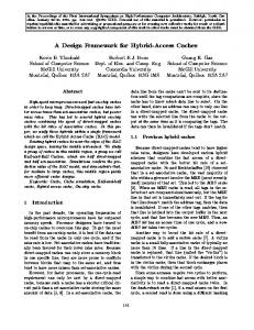
above 90% for all applications except raytrace. These results clearly imply a large amount of duplication across private caches as far as instructions are concerned. Consequently, a strategy that eliminates this duplication can bring large benefits (as there will be more available space). That is, one can increase the effective cache capacity by reducing duplications. Note that another potential problem associated with the duplicates is extra leakage energy to power the corresponding cache lines. Our objective in introducing CCC is to reduce duplicate entries as much as possible. When one looks at the data sharing in Figure 1, the picture changes. We first observe that the percentage sharing is low, averaging around 11%. However, employing CCC can still be desirable from the cache coherence viewpoint (since complex coherence protocols associated with private caches can be a major energy consumer). Based on these observations, we expect that using CCC instead of other alternatives might be very beneficial in practice.
2.1. Motivation
2.2. CCC Implementation
solution, and each bank can be simple in architecture. The experimental results obtained through cycle-accurate simulations indicate that the energy benefits of our proposed cache architecture range from 9% to 26% (when our default simulation parameters are used) with respect to the private cache option. These savings come at the expense of a small degradation in performance. Based on our results, we believe that the proposed cache architecture is very suitable for on-chip multiprocessor environments. The remainder of this paper is organized as follows. In the next section, we present some data to motivate our cache architecture. We also explain how CCC can be implemented. Section 3 gives cache energy models employed in this study. Section 4 introduces our simulation setup and presents experimental data. Finally, in Section 5, we give our conclusions.
I−Cache D−Cache
Percentage Sharing
100 80
Proc.
Proc.
Proc.
Proc.
Proc.
Proc.
Private Private Cache Cache
Private Cache
Proc.
Proc.
Proc.
Crossbar Share L1 cache
Share Share Cache Cache
Share Cache
60 40
Share L2 cache
20
Share L1 Cache
0
barnes ocean1 ocean2 radix raytrace water
Figure 1. Percentage sharing of instructions and data. The results indicate a large instruction sharing for all applications and noticeable data sharing in some of them (8 processors). To motivate CCC, we first consider data and instruction sharing between on-chip processors. Consider the graph given in Figure 1. This graph gives the percentage sharing for instructions and data when SPLASH-2 benchmarks [13] are executed using 8 processors with private L1 caches (Details of our experimental platform and benchmarks will be given later). What we mean by percentage sharing is the percentage of data or instructions shared by at least two processors when considering the entire execution of the application. Our first observation is that instruction sharing is extremely high. This is a direct result of data parallelism exploited in these benchmarks. That is, different processors typically work on (mostly) different sets of data using the same set of instructions. We observe that instruction sharing is
Share L2 cache Private L1 Cache
Share L2 cache Multibank Share L1 Cache
Figure 2. Different cache organizations used in our simulations: multi-ported shared cache, private caches, and CCC. Both data and instruction caches use these L1 configurations; however, we have only a single unified L2. In an attempt to build a high-performance cache system, we chose to use a crossbar as the interconnect between the processors and L1 banks. As compared to a bus-based architecture, the crossbar-based architecture provides simultaneous accesses to multiple cache banks (which, in turn, helps to get better performance). Figure 2 illustrates the three different cache organizations evaluated in this paper: a multi-ported shared cache, private caches, and CCC. A common characteristic of these configurations is that they all have a shared L2. In other words, they differ only in L1 organization. Due to the crossbar placed between processors and L1 banks, the pipeline stages of the processor are needed to be restructured. In our simulations, the pipeline stages of the private cache based (and multi-ported cache based) architecture are instruction fetch (IF), instruction decode (ID), execution (EX), and writeback (WB). In comparison,
the pipeline stages in the CCC-based system are instruction crossbar require (IX), IF, ID, data crossbar require (DX), EX, and WB. In the IX stage, the processor requires the instruction cache access (to a bank) through crossbar. If more than one request target the same bank, only one of them can continue with the next pipeline stage (IF), and all other processors experience a pipeline stall. In the DX stage, if the instruction is load or store, a request to the crossbar is issued. Tag#
Line#
Offset
Address format for private cache (and multi-ported shared cache) Tag#
Line#
Bank# Offset
Address format for multibank share cache
Figure 3. Address formats used by different cache organizations. The bank number field in the CCC format is used to specify the bank to access.
ETotal = EL1 + EL2
Figure 3 shows the address formats used by the private cache based system (and also the shared multi-ported cache based system) and the CCC based architecture. In the latter, a new field, called the bank number, is added. This field is used to identify the bank to be accessed. Typically, the continuous cache blocks are distributed across different banks in order to reduce the bank conflicts. While we expect CCC to be preferable over other two architectures, it can cause processor stalls when concurrent accesses to the same bank occur. To alleviate this, we can perform two optimizations. The first optimization is to use more banks than the processors. For instance, for a target on-chip multiprocessor with four processors, we can have four, eight, sixteen, or thirty-two banks. The rationale behind this is to reduce the conflicts on a given bank. The second optimization deals with the references to the same block. When two such references occur, instead of stalling one of the processors, we can read the block once and forward it to both the processors. We expect this optimization to be more successful when we have high degree of inter-processor block sharing.
3. Modeling of Energy Consumption of Cache Subsystem
(E: Energy) Ex = LEx + DEx (x: L1 or L2) (LE: Leakage Energy; DE: Dynamic Energy) LE = (NA*lea + NS*les) (NA: # of active blocks; NS: # of sleep blocks) (lea: leakage energy per active block per cycle) (les: leakage energy per sleep block per cycle) DE = (Nhit + Nmiss*2)*de + (Nhit + Nmiss)*ex (for crossbar-connected share cache) DE = (Nhit + Nmiss*2 + Ncoherence)*de (for private cache) (Nhit: # of hit; Nmiss: # of miss) (Ncoherence: # of cache coherence operation) (de: dynamic energy per access) (ex: dynamic energy per crossbar access) lea = 0.41 pJ les = 0.04 pJ
Our focus in this paper is the overall cache energy consumption. We consider both dynamic and leakage components, and use the formulation given in Figure 4. In this work, we also implement the cache leakage control strategy proposed in [7] on both L1 and L2 caches. The idea is to place a cache line into a leakage control mode if it has not been used for some time. Such a cache line is said to be in the sleep state (otherwise, it is in the active state). In these formulations, the values of lea and les are obtained from the circuit simulation of actual layouts using 70nm, 1V Berkeley predictive technology [1]. The value of de is obtained using CACTI 3.0 [11]. The value of ex is obtained by using the model proposed in [6]. The values of Nhit, Nmiss, Ncoherence, NA, and NS for L1 instruction cache, L1 data cache, L2 instruction cache, and L2 data cache are obtained from our simulations as will be discussed later. Finally, NA and NS are the total number of cache blocks in active state and sleep state, respectively, for each clock cycle.
4. Experiments
de = 104.35 pJ
(for 8K L1 cache)
ex = 7.043 pJ
(for 8X16 crossbar)
Figure 4. Formulations used for calculating cache energy consumption.
4.1. Setup and Benchmarks
Table 1. Benchmarks used in our experiments, their input parameters, and cache energy consumptions (for a private cache based system). We observe that in L1 leakage and dynamic energy consumptions are of similar magnitude, whereas in L2 dynamic energy consumption dominates (due to the leakage control mechanism). Benchmark barnes ocean1 ocean2 radix raytrace water
Input
L1 Energy (mJ) Dynamic Leakage
8192 123 0.025 0.05 1.0 2.0 5.0 0.075 0.25 8 -n258 -p8 -n258 -p8 -p8 -n2097152 -r1024 -m1048576 -p8 teapot.env 1.5e-16 512 3 6 -1 3000 3 0 8 6.212752
583.5 (59.4%)
241.4 (75.9%)
76.7 (24.1%)
0.085
21.331
102.2 (45.4%) 99.3 (38.8%)
122.8 (54.6%) 156.4 (61.2%)
90.3 (73.6%) 82.7 (68.7%)
32.4 (26.4%) 37.8 (31.3%)
0.150 0.026
39.142 31.736
87.1 (56.8%)
66.2 (43.2%)
38.2 (74.0%)
13.4 (26.0%)
0.001
25.751
91.4 (37.1%)
155.2 (62.9%)
72.3 (70.9%)
29.6 (29.1%)
6.859
16.821
145.5 (35.0%)
270.0 (65.0%)
144.4 (78.2%)
40.3 (21.8%)
0.920
34.139
We use a set of benchmarks from the SPLASH-2 suite [13]: barnes, ocean1, ocean2, radix, raytrace, and water. The important characteristics of these benchmarks are listed in Table 1. These codes differ from each other in their degree of instruction and data sharing (as pointed out earlier). We denote each cache configuration using the quadruple:
MPORT Energy Consumption (mJ)
2000 1500
500 0
MPORT IPDP
IXDX
2 processors
IPDP
IXDX
4 processors
Figure 5. Energy consumption of Ocean1 for three different cache organizations: multi-ported shared cache (MPORT), private cache based organization (IPDP), and our CCC based architecture (IXDX). One can see that the energy consumption of the multi-ported architecture is much higher than the other two. Table 2. The four cache organizations simulated in this work. Since energy consumption of a shared multi-ported cache is much higher than that of CCC, we do not consider the former. In all organizations, L2 is always shared. IPDP IXDP IPDX IXDX
L1 I-cache Private cache Multibank share cache Private cache Multibank share cache
L1 Miss rate (%) I-cache D-cache
398.0 (40.6%)
2500
1000
L2 Energy (mJ) Dynamic Leakage
L1 D-cache Private cache Private cache Multibank share cache Multibank share cache
In this study, we use MP_Simplesim [9], a multiprocessor version of Simplescalar [5], as the baseline simulator to simulate an on-chip multiprocessor. In its original form, MP_Simplesim is a functional simulator and simulates only data cache. In order to make it suitable for our study, we extended it by (1) making it cycle accurate, (2) adapting the pipeline stages to the cache architecture simulated, and (3) modifying it to simulate instruction caches (in addition to data caches).
(processors, banks/private caches, size per bank/private cache, L1 line size) The four fields in this quadruple represent the number of on-chip processors, the number of L1 banks, size per bank/private cache, and the size of an L1 block (line). It should be observed that, for the private cache-based system, the number of caches is always equal to the number of processors, whereas in our CCC-based system the number of banks might be larger than the number of processors. Also, for a given experiment, we always kept the number and capacities of the data and instruction caches the same. As an example, a configuration such as (4,8,4KB,32B) indicates 4 processors and 8 banks (each is 4KB with 32 byte lines). Our initial experiments with the multi-ported shared cache indicated that its energy consumption is much higher than those of the CCC and the private cache-based system. This is due to the excessive access energy associated with increased capacity and multiple ports. As an example, as shown in Figure 5, when running one of our applications, namely ocean1, the energy consumption of the multi-ported cache was 2.91 times higher than that of CCC for 2 processors system and 7.83 times higher for 4 processors. Therefore, in the remainder of this paper, we focus on only CCC and private cache based configuration. Table 2 lists the cache configurations evaluated in our simulations. Unless stated otherwise, (8,16,4KB,32B) is our default CCC configuration and (8,8,8KB,32B) is the default for the private cache based architecture. Note that in both the cases, the total cache capacity is the same.
4.2. Results
IPDP IXDP IPDX IXDX
IL1 DL1 IL2 DL2
100 80 60
0
barnes ocean1 ocean2
radix
raytrace water
120
IPDP IXDP IPDX IXDX
IL1 DL1 IL2 DL2
100 80 60 40 20 0
2 procs
4 procs
8 procs
16 procs
100
20 0
barnes
ocean1
ocean2
radix
raytrace
water
Figure 7. Performance for different benchmarks on our default configuration [(8,16,4KB,32B) for CCC and (8,8,8KB,32B) for the private cache based system]. The results are normalized with respect to IPDP. We start by presenting the results of six SPLASH-2 codes for our default configurations. The (cache) energy consumptions and performance results (execution cycles) are given in Figure 6 and Figure 7, respectively. We see from these results that the best energy behavior is obtained when we use the CCC for both instruction and data caches (that is, the IXDX version). The percentage energy savings with respect to IPDP range from 9.34% to 26.34%, averaging on 17.04%. When we look at the performance results, we observe a maximum 4.73% degradation in performance (again, as compared to IPDP) when IXDX is employed. The reasons that we have very good savings in energy consumption are (1) CCC removes the energy overhead on cache coherence in L1 data cache, (2) CCC has a larger effective L1 cache size than the
120
IXDX
40
IPDX
60
IXDP
Figure 8. Energy consumptions with different number of processors. The results are normalized with respect to IPDP on two processors.
80
IPDP
Normalized Execution Cycles (%)
Figure 6. Energy consumptions for different benchmarks on our default configuration [(8,16,4KB,32B) for CCC and (8,8,8KB,32B) for the private cache based system]. The results are normalized with respect to IPDP.
IPDP IXDP IPDX IXDX
20
Normalized Energy Consumption (%)
4.2.2. Impact of the Number of processors
40
Normalized Execution Cycles (%)
Normalized Energy Consumption (%)
4.2.1. Base Results
private cache based system, (3) CCC reduces the miss rate of L1 instruction and data caches and, as a result, (4) it reduces the number of L2 cache access. On the other hand, the main reason for the increase in execution cycles in some benchmarks is the bank conflicts. Despite this, in three of our benchmarks (ocean2, radix, raytrace), IXDX slightly improves execution cycles (over IPDP) due to eliminating the duplicates. In the rest of our presentation, we focus only on a single benchmark as our experiments with other benchmarks led to similar observations.
100 80 60 40 20 0
2 procs
4 procs
8 procs
16 procs
Figure 9. Performance with different number of processors. The results are normalized with respect to IPDP on two processors. To study the impact of the number of on-chip processors, we performed experiments with 2, 4, 8, and 16 processors using the ocean1 benchmark. The energy and performance results are shown in Figures 8 and 9. In the CCC-based configuration, we always used 2x banks for x processors. When the number of the processors increases, the energy consumption of the private cache based system increases and that of the CCC based system remains the same. These results indicate that the effectiveness of our
IXDX
IPDX
IXDP
IPDP
IL1 DL1 IL2 DL2
100 80 60
IPDP IXDP IPDX IXDX
IL1 DL1 IL2 DL2
100 80 60 40 20 0
2K
40
8K
16K
IXDX
IPDX
IXDP
IPDP
100 80 60 40
IXDX
32 banks
IPDX
16 banks
IXDP
8 banks
IPDP
0
100 80 60 40 20 0
2K
4K
8K
16K
Figure 13. Performance with different L1 cache size. The results are normalized with respect to IPDP.
20 0
4K
Figure 12. Energy consumptions with different L1 cache size. The results are normalized with respect to IPDP.
20
Figure 10. Energy consumptions with different number of banks (8 processors). The results are normalized with respect to the first bar.
Normalized Execution Cycles (%)
4.2.4. Impact of L1 Cache Capacity
Normalized Execution Cycles (%)
Normalized Energy Consumption (%)
4.2.3. Impact of the Number of Banks
conflicts. It should be mentioned that while increasing the number of banks seems to be beneficial from the performance perspective, it may not be a very scalable approach as large number of banks also poses an area and interconnection cost problem. This last issue is beyond the scope of this paper.
Normalized Energy Consumption (%)
strategy increases with the increased number of processors. This is because of three major reasons. First, for the private cache based system, as we increase the number of processors, the dynamic energy spent in coherence activity increases. Second, increasing the number of caches (in the private cache-based system) tends to increase sharing, which in turn reduces the effective cache utilization. Third, increasing the number of banks (in CCC) reduces the number of bank conflicts. This helps both energy and performance.
8 banks
16 banks
32 banks
Figure 11. Performance with different number of banks (8 processors). The results are normalized with respect to the first bar. Our next set of experiments investigate the impact of the number of banks on energy consumption of the CCC based architecture. For this purpose, we performed experiments with 8 banks, 16 banks, and 32 banks using the ocean1 benchmark. The results given in Figures 10 and 11 clearly indicate that while there is not too much difference in energy behavior, CCC results in better execution time when we use a larger number of banks. The main reason for this is the reduced number of bank
In our next set of experiments, we modified L1 capacity (size). The values that we experimented with are 2KB, 4KB, 8KB, and 16KB. All other parameters are the same as in the default configuration. The results are given in Figures 12 and 13. Our observation is that the CCCbased architecture still remains better than the private cache based system when L1 cache size is increased. However, if the L1 cache size is made large enough to capture the working set of the application, the difference between CCC and the private cache based system reduces. In our case, this happens with a 16KB cache size.
4.2.5. Impact of L1 Line Size
IPDP IXDP IPDX IXDX
Normalized Energy Consumption (%)
IL1 DL1 IL2 DL2
100 80 60 40 20 0
8 Bytes
16 Bytes
32 Bytes
64 Bytes
Normalized Execution Cycles (%)
Reference
IXDX
IPDX
IXDP
IPDP
Figure 14. Energy consumption for different L1 cache line size. The results are normalized with respect to IPDP.
cache organization to combine their advantages. The idea is to divide the L1 cache into multiple banks, and connect the processors to banks using a crossbar interconnect. The results obtained using cycle-accurate simulation and several SPLASH-2 benchmarks indicate that the energy benefits of our proposed cache architecture range from 9% to 26% (when our default simulation parameters are used) with respect to the private cache option. These savings come at the expense of a small degradation in performance in some benchmarks (whereas our approach improves performance in some others). Based on our results, we believe that the proposed cache architecture is very suitable for on-chip multiprocessor environments.
100
[1]
80
[2]
60
[3]
40
[4]
20 0
8 Bytes
16 Bytes
32 Bytes
64 Bytes
Figure 15. Performance for different L1 cache line size. The results are normalized with respect to IPDP. In our last set of experiments, we modified the L1 cache line size. The values we experimented with include 8B, 16B, 32B, and 64B, and the energy and performance results are depicted in Figure 14 and Figure 15. We can see from these results that increasing the cache line size increases the chances for multiple accesses to the same cache line. Thanks to the optimization discussed in Section 2, we reduce these types of conflicts significantly. As a result, the performance of the CCC-based architecture improves, and we also observe an improvement in energy behavior. These experimental results indicate that our CCCbased cache architecture takes advantage of increased number of on-chip processors and of banks, increased cache capacity and line size. Since these are also the trends that we observe in the architecture area, we can expect the proposed cache architecture to be even more successful in the future.
5. Concluding Remarks Observing that both private cache based system and multi-ported shared cache architecture have advantages and disadvantages, this paper proposes an alternative
[5]
[6]
[7]
[8]
[9]
[10]
[11]
[12]
[13]
Berkeley predictive model. http://www-device.eecs.berkeley.edu IBM power4 project. http://www-1.ibm.com/servers/eserver/pseries/hardware/ whitepapers/power4.html Stanford Hydra project. http://www-hydra.stanford.edu Sun MAJC project. http://www.sun.com/products/processors/majc/ D. C. Burger and T. M. Austin, “The SimpleScalar toolset, Version 2.0”, Technical Report 1342, Dept. of Computer Science, UW, June 1997. G. Essakimuthu, N. Vijaykrishnan, and M. J. Irwin, “An analytical power estimation model for crossbar interconnects”, In IEEE International ASIC/SOC Conference, Sept 2002. K. Flautner, N. Kim, S. Martin, D. Blaauw, and T. Mudge, “Drowsy caches: Simple techniques for reducing leakage power”, In ISCA-29, May 2002. T. Koyama, K. Inoue, H. Hanaki, M. Yasue, and E. Iwata, “A 250-mhz single-chip multiprocessor for audio and video signal processing”, IEEE Journal of Solid-State Circuits, 36(11):1768–1774, 2001. N. Manjikian, “Multiprocessor enhancements of the simplescalar tool set”, ACM SIGARCH Computer Architecture News, 29(1):8–15, 2001. K. Olukotun, B. A. Nayfeh, L. Hammond, K. Wilson, and K. Chang, “The case for a single-chip multiprocessor”, In ASPLOS IIV, pp. 2–11, 1996. P. Shivakumar and N. P. Jouppi, “Cacti 3.0: An Integrated Cache Timing, Power and Area Model”, Technical report, Western Research Lab (WRL), Feb 2001. M. Takahashi, H. Takano, E. Kaneko, and S. Suzuki, “A shared-bus control mechanism and a cache coherence protocol for a high-performance on-chip multiprocessor”, In HPCA’96, pp. 314–322, Feb. 1996. S. C. Woo, M. Ohara, E. Torrie, J. Singh, and A. Gupta, “The splash-2 programs: characterization and methodological considerations”, In ISCA-22, pp. 24–36, 1995.